Language selection

Search

Patent 2262167 Summary

Third-party information liability

Some of the information on this Web page has been provided by external sources. The Government of Canada is not responsible for the accuracy, reliability or currency of the information supplied by external sources. Users wishing to rely upon this information should consult directly with the source of the information. Content provided by external sources is not subject to official languages, privacy and accessibility requirements.

Claims and Abstract availability

Any discrepancies in the text and image of the Claims and Abstract are due to differing posting times. Text of the Claims and Abstract are posted:

  • At the time the application is open to public inspection;
  • At the time of issue of the patent (grant).
(12) Patent: (11) CA 2262167
(54) English Title: SLIDE IDLER FOR A CHAIN DRIVE
(54) French Title: GALET-TENDEUR COULISSANT POUR ENTRAINEMENT A CHAINE
Status: Expired and beyond the Period of Reversal
Bibliographic Data
(51) International Patent Classification (IPC):
  • F16H 07/08 (2006.01)
  • F16H 07/12 (2006.01)
(72) Inventors :
  • LODICO, JAMES IRWIN (United States of America)
  • OSTRANDER, JEREMY SHANE (United States of America)
  • PLATTNER, CHAD ERIC (United States of America)
(73) Owners :
  • DEERE & COMPANY
(71) Applicants :
  • DEERE & COMPANY (United States of America)
(74) Agent: BORDEN LADNER GERVAIS LLP
(74) Associate agent:
(45) Issued: 2003-09-16
(22) Filed Date: 1999-03-01
(41) Open to Public Inspection: 2000-02-17
Examination requested: 1999-03-01
Availability of licence: N/A
Dedicated to the Public: N/A
(25) Language of filing: English

Patent Cooperation Treaty (PCT): No

(30) Application Priority Data:
Application No. Country/Territory Date
09/135,227 (United States of America) 1998-08-17

Abstracts

English Abstract


A slide idler for a chain drive wherein the idler is provided with easily
replaceable
and rotatable bushings. The slide idler comprises two elongated members, each
elongated
member is provided with two inwardly extending polygonal mounting assemblies.
Two
cylindrical bushings having polygonal apertures corresponding to the polygonal
mounting
assemblies are mounted to these mounting assemblies and are sandwiched between
the
elongated members. A split pin is used to hold the slide idler together.


Claims

Note: Claims are shown in the official language in which they were submitted.

The embodiments of the invention in which an exclusive property or privilege
is claimed are defined as follows:
1. A slide idler for a chain drive, the idler comprising:
a first elongated member and a second elongated member, both elongated members
having a first inwardly extending polygonal mounting assembly and a second
inwardly
extending polygonal mounting assembly, each of the mounting assemblies having
an
aperture extending therethrough;
two replaceable cylindrical bushings each having a polygonal aperture for
receiving
the polygonal mounting assemblies of the elongated members, the cylindrical
bushings are
sandwiched between the elongated members with one of the cylindrical bushings
wherein
both elongated members have first inwardly extending polygonal mounting
assembly and a
second inwardly extending polygonal mounting assembly and the replaceable
cylindrical
bushings are provided with polygonal apertures for receiving the polygonal
mounting
assemblies rendering the cylindrical bushing non-rotatable being mounted on
the first
inwardly extending mounting assemblies on both elongated members and the other
cylindrical bushing being mounted an the second inwardly extending mounting
assemblies of
both elongated members rendering the cylindrical bushings non-rotatable.
2. A slide idler as defined by claim 1 further comprising a split pin which is
inserted
through apertures in the first inwardly extending mounting assemblies for
securing both
elongated members together about the cylindrical bushings.
3. A slide idler as defined by claim 2 wherein the split pin is provided with
a cap
having an underside for abutting the first elongated member.
4. A slide idler as defined by claim 3 wherein the split pin is provided with
two
resilient legs.
5. A slide idler as defined by claim 4 wherein each of the resilient legs are
provided
with a boss having an abutment surface for engaging the second elongated
member.
6. A slide idler as defined by claim 5 wherein the apertures extending through
the
mounting assemblies are circular.
7. A chain drive, the chain drive comprising:
a drive sprocket;
a driven sprocket;
a chain interconnecting the drive sprocket and the driven sprocket;
a frame having a spindle;
a slide idler is mounted to the spindle of the frame, the slide idler is
provided with first
and second elongated members and two replaceable cylindrical bushings are
sandwiched
between the elongated members, the chain passes between the two cylindrical
bushings
and contacts both cylindrical bushings.

8. A chain drive as defined by claim 7 wherein each of the polygonal mounting
assemblies have an aperture extending therethrough, one of the apertures is
mounted over
the spindle of the frame.
9. A chain drive as defined by claim 8 further comprising a spring extending
between
the frame and the slide idler for biassing the cylindrical bushings of the
idler into contact with
the chain.
10. A chain drive as defined by claim 9 wherein the spring extends between the
spindle of the frame and one of the elongated members.
11. A chain drive as defined by claim 9 further comprising a split pin which
is
inserted through apertures in the aperture opposite from where the spindle is
inserted for
securing both elongated members together about the cylindrical bushings.
12. A chain drive as defined by claim 11 wherein the split pin is provided
with a cap
having an underside for abutting the first elongated member.
13. A chain drive as defined by claim 12 wherein the split pin is provided
with two
resilient legs.
14. A chain drive as defined by claim 13 wherein each of the resilient legs
are
provided with a boss having an abutment surface for engaging the second
elongated
member.
15. A slide idler for a chain drive, the idler comprising:
a first elongated member and a second elongated member, both elongated members
having a first inwardly extending polygonal mounting assembly and a second
inwardly
extending polygonal mounting assembly, the polygonal mounting assemblies
define a series
of mounting locations;
two replaceable cylindrical bushings each having a polygonal aperture for
receiving
the polygonal mounting assemblies of the elongated members, the cylindrical
bushings are
sandwiched between the elongated members with one of the cylindrical bushings
being
mounted on the first inwardly extending mounting assemblies on both elongated
members
and the other cylindrical bushing being mounted on the second inwardly
extending mounting
assemblies of both elongated members rendering the cylindrical bushings non-
rotatable, the
cylindrical bushings can be placed in different mounting locations as defined
by the
polygonal mounting assemblies.

Description

Note: Descriptions are shown in the official language in which they were submitted.


CA 02262167 2002-11-26
SLIDE IDLER FOR A CHAIN DRIVE
Background of the Invention
1. Filed of the invention:
The invention is directed to a slide idler for a chain drive having
replaceable and
positionable cylindrical bushings.
2. Description of the Prior Art:
Idlers for chain drives are well known in the art. These idlers are usually
spring
biassed to apply a tension to the chain so it does not become uncogged from
the driven or
driven sprockets. Some idlers are provided with freely rotatable sprockets for
engaging the
chain. Other idlers such as slide idlers are made of plastic material and are
provided with
cylindrical surfaces that slide along the chain.
One design of a slide idler, uses two elongated members having two cylindrical
bushings sandwiched therebetween. The bushings are affixed to the elongated
members.
Cylindrical apertures pass through the elongated members and the bushings. The
bushing
is mounted on a spindle of a frame and a spring is positioned between the
spindle and the
idler to bias it into contact with the chain. The bushings of this idler
cannot be replaced or
rotated into different engagement positions.
Summary of the Invention
The slide idler of the present invention is provided with two elongated
members.
Each elongated member is provided with a first inwardly extending polygonal
mounting
assembly and a second inwardly extending polygonal mounting assembly. Two
replaceable
cylindrical bushings having polygonal apertures are mounted to the mounting
assemblies
and are sandwiched between the elongated members. The mounting assemblies
define
cylindrical apertures passing through the idler. One of these cylindrical
apertures would be
mounted on a spindle that forms part of a frame. The other cylindrical
apertures is provided
with a spilt pin having resilient legs for holding the idler together. By
pinching the legs of the
pin the idler can be taken apart and the cylindrical bushings can be rotated
or replaced as
required.
In a chain drive having a drive sprocket a driven sprocket and an entraining
chain,
the chain passes between the cylindrical bushings. The idler is secured to a
spindle of a
frame and is biassed into engagement with the chain by a spring extending
between the
spindle and the idler.
Brief Descr j~tion o1' the Drawings
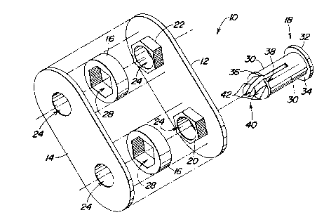
Figure 1 is an exploded view of the slide idler of the present invention.
Figure 2 is a chain drive in which the slide idler of the present invention is
used.

CA 02262167 2002-11-26
Detailed Description
The slide idler 10 illustrated in Figure 1 comprises a first elongated member
12, a
second elongated member 14, two replaceable cylindrical bushings 16 and a
split pin 18.
Both elongated members are provided with a first inwardly extending polygonal
mounting
assembly 20 and a second polygonal mounting assembly 22. In the illustrated
embodiment, the polygonal mounting assemblies are six sided but other
configurations could
also be used. A circular aperture 24 passes through the mounting assemblies.
Two
cylindrical bushings 16 are sandwiched between the elongated members '12 and
14. Both
bushings are provided with polygonal apertures 28 into which are inserted the
corresponding
polygonal mounting assemblies and render the cylindrical bushings non-
rotatable. The split
pin 18 is provided with resilient legs 30 and is inserted into one of the
circular apertures 24
for holding the slide idler 10 together. To hold the slide idler together the
split pin is provided
with a cap 32 having and underside 34 for abutting the exterior surface of the
first elongated
member 12. In addition both split pin legs 30 are provided with a boss 36
having an
abutment surface 38 for abutting the second elongated member 14.
In assembling the slide idler 10, the two cylindrical bushings 16 are first
mounted on
the first and second mounting assemblies of the first elongated member 12. The
second
elongated 14 and its corresponding mounting assemblies are then pressed over
the
mounted bushings 16 securing the elongated members 12 and 14 together and
sandwiching the bushings 16 therebetween. The conical portion 40 of the split
pin 18 is
inserted into one of the circular apertures 24 compressing the resilient legs
30. The split pin
18 is then pushed into the circular aperture 24 until the underside 34 of the
cap 32 bears
against the exterior surface of the first elongated member 12. The pin 18 is
sized so that
when the underside 34 engages the first elongated member, the boss 36 has
passed
through the second elongated member 14 and its of the abutment surface 38 has
engaged
the exterior surface of the second elongated member 14 as the legs 30
resiliently spring
back apart.
To take the slide idler apart the process is reversed with the operator
pinching the
conical portion 40 compressing the split legs 30. The conical portion is
provided with flat
engagement surfaces 42 to facilitate this operation. The pin 18 is pushed
through the
circular aperture 24 and the elongated members 12 and 14 are pulled apart
releasing the
cylindrical bushings 16.
Figure 2 illustrates the mounting the slide idler 10 to a chain drive 48. The
chain
drive 48 is provided with a drive sprocket 50, a driven sprocket 52 and a
chain 54 entrained
2

CA 02262167 2002-11-26
about the sprockets 50 and 52. The slide idler 10 is pivotally mounted to a
frame 56 on a
spindle 58. The chain 54 extends between the circular bushings 16 contacting
both
bushings. The bushings 16 are biased against the chain 54 by a spring 80. The
spring
extends between the spindle 58 and the elongated members 12 and 14 biasing the
slide
idler 10 counterclockwise so that the circular bushings 16 engage the chain
54.
The interior surfaces of the elongated members form ~~ guide mechanism for
guiding
the chain and limiting its transverse displacement thereby keeping it in
better alignment.
The slide idler 10 can be taken apart on the chain without removing the chain.
This
enables the operator to replace the circular bushings 16 or rotate the
bushings as needed.
The slide idler design of the present invention is a relatively simple design
with only
three different parts two identical elongated members, two identical
cylindrical bushings and
a split pin. The elongated members and the cylindrical bushings are made from
a rigid wear
resistant plastic, whereas the split pin is made from a resilient plastic.
The invention should not be limited to the above described embodiment, but
should
be limited solely to the claims that follow.
3

Representative Drawing
A single figure which represents the drawing illustrating the invention.
Administrative Status

2024-08-01:As part of the Next Generation Patents (NGP) transition, the Canadian Patents Database (CPD) now contains a more detailed Event History, which replicates the Event Log of our new back-office solution.

Please note that "Inactive:" events refers to events no longer in use in our new back-office solution.

For a clearer understanding of the status of the application/patent presented on this page, the site Disclaimer , as well as the definitions for Patent , Event History , Maintenance Fee  and Payment History  should be consulted.

Event History

Description Date
Time Limit for Reversal Expired 2011-03-01
Letter Sent 2010-03-01
Inactive: IPC from MCD 2006-03-12
Grant by Issuance 2003-09-16
Inactive: Cover page published 2003-09-15
Inactive: Final fee received 2003-06-19
Pre-grant 2003-06-19
Notice of Allowance is Issued 2003-01-22
Letter Sent 2003-01-22
Notice of Allowance is Issued 2003-01-22
Inactive: Approved for allowance (AFA) 2003-01-02
Amendment Received - Voluntary Amendment 2002-11-26
Inactive: S.30(2) Rules - Examiner requisition 2002-06-04
Application Published (Open to Public Inspection) 2000-02-17
Inactive: Cover page published 2000-02-16
Classification Modified 1999-03-31
Inactive: First IPC assigned 1999-03-31
Inactive: IPC assigned 1999-03-31
Inactive: Filing certificate - RFE (English) 1999-03-16
Application Received - Regular National 1999-03-16
Request for Examination Requirements Determined Compliant 1999-03-01
All Requirements for Examination Determined Compliant 1999-03-01

Abandonment History

There is no abandonment history.

Maintenance Fee

The last payment was received on 2003-02-28

Note : If the full payment has not been received on or before the date indicated, a further fee may be required which may be one of the following

  • the reinstatement fee;
  • the late payment fee; or
  • additional fee to reverse deemed expiry.

Patent fees are adjusted on the 1st of January every year. The amounts above are the current amounts if received by December 31 of the current year.
Please refer to the CIPO Patent Fees web page to see all current fee amounts.

Owners on Record

Note: Records showing the ownership history in alphabetical order.

Current Owners on Record
DEERE & COMPANY
Past Owners on Record
CHAD ERIC PLATTNER
JAMES IRWIN LODICO
JEREMY SHANE OSTRANDER
Past Owners that do not appear in the "Owners on Record" listing will appear in other documentation within the application.
Documents

To view selected files, please enter reCAPTCHA code :


To view images, click a link in the Document Description column. To download the documents, select one or more checkboxes in the first column and then click the "Download Selected in PDF format (Zip Archive)" or the "Download Selected as Single PDF" button.

List of published and non-published patent-specific documents on the CPD .

If you have any difficulty accessing content, you can call the Client Service Centre at 1-866-997-1936 or send them an e-mail at CIPO Client Service Centre.


Document
Description 
Date
(yyyy-mm-dd) 
Number of pages   Size of Image (KB) 
Representative drawing 2000-02-06 1 16
Claims 2002-11-25 2 119
Description 2002-11-25 3 164
Abstract 1999-02-28 1 14
Description 1999-02-28 3 143
Claims 1999-02-28 2 102
Drawings 1999-02-28 1 33
Courtesy - Certificate of registration (related document(s)) 1999-03-15 1 117
Filing Certificate (English) 1999-03-15 1 165
Reminder of maintenance fee due 2000-11-01 1 112
Commissioner's Notice - Application Found Allowable 2003-01-21 1 160
Maintenance Fee Notice 2010-04-11 1 171
Correspondence 2003-06-18 1 25