Note: Descriptions are shown in the official language in which they were submitted.
CA 02262265 1999-02-19
Le A 32 737 BW/FC
Apparatus for concentrating and purifying sulfuric acid
This invention relates to an apparatus for concentrating and purifying
sulfuric acid
which allows sulfuric acid to be concentrated at 270-340°C to an H,S04
content of
95-98%. The parts of the apparatus which convey sulfuric acid consist of
austenitic
or austenitic/ferritic steels.
It is known to concentrate waste sulfuric acid to approx. 96% under slightly
reduced
pressure and temperatures in the range from 300 to 320°C (Winnacker,
Kiichler,
Chemische Technologie, volume 2, 4'h edition 1982, pp. 67-70).
In the so-called Pauling process, waste sulfuric acid is evaporated from an
HZSO~
content of 70-85% to 95-96% in cast iron boilers indirectly heated with flue
gases
and equipped with a distillation column. Considerable corrosive losses must
always
1 S be allowed for in the production of the boilers by means of large wall
thicknesses.
The ratio of heat transfer surface to boiler volume in such apparatus is
highly
unfavourable. Such plants consequently constitute a considerable safety hazard
because, in the event of boiler failure, approx. 10 m3 of boiling 96% sulfuric
acid
could flow into the combustion chamber, which is at a temperature of approx.
750°C. In the drum concentrator, the sulfuric acid is concentrated by
direct contact
with hot flue gases. The exhaust gases are contaminated with SO~, sulfuric
acid
vapour, nitrogen oxides and optionally organic compounds, so entailing
considerable
purification costs due to the large specific exhaust gas volume.
Achieving a high degree of concentration in a falling film evaporator made
from
silica glass (EP-A 22 473) has only been possible to implement in small units.
The
same applies to the high degree of concentration described in DE-A 2 909 029
which
is achieved by means of IR heat sources made from silica glass immersed in the
sulfuric acid.
CA 02262265 1999-02-19
LeA32737
_2_
Vacuum evaporators having heat exchangers made from tantalum (cf. for example
EP-A 156 199) are restricted to a temperature range of below 200°C.
At such
temperatures, sulfuric acid may only be evaporated to 95-96% under extremely
reduced pressures, so entailing specifically large plant size per unit
evaporating
output and high costs for producing the vacuum and condensing the vapours.
Moreover, the conditions for oxidative degradation of organic impurities are
also
very unfavourable due to the low acid temperature.
The object was accordingly to develop an apparatus which makes it possible to
achieve highly efficient water evaporation with a low sulfuric acid content at
temperatures in the range above 250°C and optionally to permit
oxidative
purification.
The object was achieved according to the invention by an apparatus for
concentrating
sulfuric acid to an HZSOa content of 95-98% and optionally for purifying the
sulfuric
acid at a temperature of 270 to 340°C, consisting of at least a
naturally circulating
evaporator system comprising a two-part vapour hood, a heat exchanger, in
particular a shell-and-tube heat exchanger, circulating line and distillation
column,
characterised in that the parts of the apparatus conveying the liquid sulfuric
acid at a
temperature of 270 to 340°C comprising the lower part of the vapour
hood, heat
exchanger and circulating line consist of an austenitic/ferritic iron alloy
containing
silicon of the following composition
from 13 to 32 wt.% of chromium
from 5 to 25 wt.% of nickel
from 4 to 9 wt.% of silicon
max. 0.07 wt.% of carbon
max. 0.03 wt.% of sulfur
max. 0.03 wt.% of phosphorus
max. 8 wt.% of manganese
max_ 3 wt.% of molybdenum
CA 02262265 1999-02-19
T _ A 11 rl ~1 ~7
-3-
max. 4 wt.% of copper
max. 20 wt.% of cobalt
max. 4 wt.% of tungsten
max. 2 wt.% of niobium and tantalum
max. 0.2 wt.% of nitrogen
and a remainder to make up to 100 wt.% of iron with a structure having a delta
ferrite fraction of between 10 and 65%, preferable containing at least 20
percent by
weight Fe,
or of austenitic iron alloys comprising
from 10 to 12 wt.% of chromium
from 15.5 to 17.5 wt.% of nickel
from 5.7 to 6.5 wt.% of silicon
max. 0.06 wt.% of carbon
max. 0.03 wt.% of phosphorus
max. 0.03 wt.% of sulfur
max. 1.5 wt.% of manganese
max. 0.15 wt.% of titanium
max. 0.8 wt.% of zirconium
max. 0.2 wt.% of nitrogen
max. 0.3 wt.% of molybdenum
max. 0.01 wt.% of boron
max. 0.25 wt.% of rare earth metals
max. 1 wt.% of magnesium, aluminium and
calcium
and a remainder to to
make up 100
wt.%
of
iron
or
from 8 to 16 wt.% of chromium
from 20 to 30 wt.% of nickel
from >6.5 to 7.4 wt.% of silicon
max. 0.03 wt.% of carbon
max. 0.03 wt.% of phosphorus
CA 02262265 1999-02-19
Le A 32 737
-4-
max. 0.01 wt.% of sulfur
max. I wt.% of magnesium, aluminium and calcium
and a remainder up to 100 wt.% of iron,
and in which the upper part of the vapour hood and the distillation column
consist of
enamelled steel.
The lower part of the vapour hood is preferably provided with a discharge pipe
made
from an iron alloy containing silicon which ends with an outlet in an
immersion vessel
made from iron alloy containing silicon or enamelled steel.
In a preferred embodiment, the circulating line has an additional discharge
port
and/or a port for introducing gases, for example air or inert gas, in order to
increase
the acid circulation speed and/or for introducing oxidising agents, for
example
sulfuric acid, hydrogen peroxide, ozone, nitrosylsulfuric acid.
The heat exchanger of the apparatus is in particular a shell-and-tube heat
exchanger,
through the tubes of which the circulating sulfuric acid flows, and which is
heated by
flue gas or electricity.
The tubes of the heat exchanger preferably comprise bimetallic tubes, wherein
the
inner tube consists of the same iron alloy containing silicon as the lower
part of the
vapour hood and the outer tube consists of heat-resistant steel.
In another preferred embodiment, the lower part and upper part of the vapour
hood
are joined together by a pair of flanges, wherein the flange of the lower part
consists
of the same iron alloy containing silicon as the lower part of the vapour
hood.
In a preferred embodiment of the invention, the flange of the lower part of
the vapour
hood has at least two annular grooves to accommodate seals.
CA 02262265 1999-02-19
LeA32737
_5_
In a particularly preferred embodiment of the invention, the parts of the
apparatus
which consist of iron alloys containing silicon are provided with a
superficial
passivating layer which is produced by at least 24 hours treatment with 95 to
98%
sulfuric acid at 290 to 340°C, preferably by at least 12 hours
treatment with 95 to
98% sulfuric acid, which contains at least 350 ppm of nitrosylsulfuric acid,
at a
temperature of 250 to 340°C, or with 95 to 100% nitric acid at a
temperature of 70
to 90°C, wherein the pressure selected is suff=iciently high that the
liquid does not
boil.
The packing of the distillation column is in particular made from glass, cast
silicon
iron or ceramics.
The present invention also provides a process for concentrating sulfuric acid
to a
concentration of 95 to 98% using the apparatus according to the invention,
which
process is characterised in that the apparatus is charged with sulfuric acid
of a
concentration of 70 to 93% and the sulfuric acid is distilled at a pressure of
0.3 to
1.2 bar (abs.), preferably of 0.8 to 0.99 bar (abs.) and a temperature of 270
to 340°C,
preferably of 280 to 320°C.
Purification of the sulfuric acid is in particular achieved by introducing
oxidising
agents such as nitrosylsulfuric acid, nitric acid, hydrogen peroxide. ozone or
others
into the circulating sulfuric acid. If the introduction is made beneath the
heat
exchanger, the circulation speed of the liquid acid is advantageously
increased by the
resultant reaction gases.
The present invention also provides the use of the apparatus according to the
invention for concentrating and optionally purifying sulfuric acid.
One disadvantage of known sulfuric acid evaporating plants made from enamelled
steel is the numerous flange connections which cause problems, especially at
relatively high operating temperatures. In the apparatus according to the
invention,
CA 02262265 1999-02-19
LeA32737
-6-
flange connections may be entirely avoided in those parts of the plant
containing hot
liquid sulfuric acid, as the alloys used according to the invention are
weldable.
It is, however, preferred to use flange connections wherever appropriate for
plant
design or processing reasons, in particular with regard to cleaning
requirements.
Particularly preferred flange connections are those of the groove and spring
designs.
Compensators, which are required to offset the thermal expansion of plant
components made from the same iron alloy containing silicon as the lower part
of the
vapour hood, may also be used.
The apparatus components made from iron alloys containing silicon are
preferably
subjected to a passivating surface treatment before the intended commissioning
thereof for concentrating sulfuric acid. The preferred treatment is for at
least 24
I S hours with 95 to 98% sulfuric acid at 250 to 340°C, preferably for
at least 12 hours
with 95 to 98% sulfuric acid which contains at least 350 ppm of
nitrosylsulfuric acid
at a temperature of 250 to 340°C or with 95 to 100% nitric acid for at
least 12 hours
at a temperature of 70 to 90°C and under a pressure at which the liquid
does not boil.
The apparatus according to the invention for concentrating and optionally
purifying
sulfuric acid provides various advantages in comparison with prior art
apparatus:
The materials and heating media used allow the apparatus to be operated at 270
to
340°C and a pressure of 0.3 to I.2 bar (abs.), preferably of 0.8 to
0.99 bar (abs.).
In comparison with plants having tantalum heat exchangers, which may be
operated
at a maximum of 200°C, the apparatus according to the invention permits
the
optimum operating conditions for destroying organic impurities in the sulfuric
acid
while simultaneously minimising vapour condensation costs.
CA 02262265 1999-02-19
LeA32737
_7_
The comparatively high operating pressure moreover permits small apparatus
dimensions, so reducing the capital costs for the plant.
In comparison with known Pauling plants, the specific acid content (relative
to water
evaporating output) is only 10 to 20%. It is particularly advantageous that in
the
event of leakage, the released acid may straightforwardly be retained in a
bund,
whereas leaks from Pauling boilers pass into the boiler furnace chamber and
thus
cause considerable S03 emissions.
Due to the possible large temperature difference between heating medium and
sulfuric acid. the specific heat exchange surface required is very small in
comparison
with plants which must be heated with steam or heat-transfer oil.
The parts made from iron alloy containing silicon are preferably all covered
with
liquid sulfuric acid during operation. This ensures that no corrosive sulfuric
acid of a
lower concentration can cause corrosion damage to the apparatus by
condensation at
cold points.
Producing the upper part of the vapour hood from enamelled steel has the
advantage
that the condensates containing dilute sulfuric acid which occur in this part
may
readily be processed according to the invention without leaving corrosion
damage on
the walls of the upper part of the vapour hood. Other corrosion processes
accordingly proceed in this section of the apparatus than in the area of the
lower part
of the vapour hood or in the naturally circulating portion.
Since all parts of the apparatus which contain liquid sulfuric acid at a
temperature of
above 270°C may be joined together by welds or groove and spring
flanges, the
apparatus according to the invention suffers no sealing problems.
The invention is illustrated in greater detail below by the figures, without
the
invention consequently being limited by specific details.
CA 02262265 1999-02-19
LeA32737
_g_
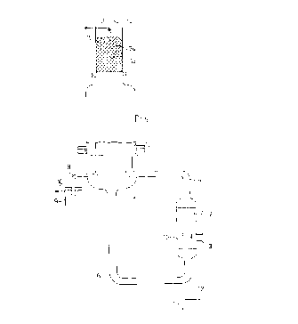
The figures show
Figure 1 a schematic representation of one embodiment of the apparatus
according to the invention
Figure 2 an magnified representation of the flange connection between the
lower part (4) and upper part (5) of the vapour hood of the apparatus
according figure 1.
CA 02262265 1999-02-19
Le A 32 737
-9-
Example
Figure I shows the schematic structure of the concentration apparatus. The
apparatus
consists of a two part vapour hood 4, 5, a shell-and-tube heat exchanger I, a
circulating line 6, 7 and a distillation column 13, which together form a
naturally
circulating evaporator system.
The parts of the heat exchanger I which come into contact with sulfuric acid
consist
of iron alloy containing silicon with 5.94% Si, 17.49% Ni, I 1.34% Cr, 62.7%
Fe and
comprise bimetallic tubes 16 with an inner tube 17 consisting of the iron
alloy
containing silicon and an outer tube 18 made from heat-resistant steel I
.4593.
The circulating line 6 is provided with a discharge port I I and with a port
12 for
introducing air or oxidising agents (65% HN03; sulfuric acid saturated with
nitrosylsulfuric acid) for destroying organic compounds.
An overflow tube 8 passes through the wall of the lower part 4 of the vapour
hood,
through which tube the hot concentrated sulfuric acid is discharged into the
immersion vessel 9, from which it flows through the port 10 into a receiver or
an acid
condenser. All the parts of the apparatus hitherto described, which come into
contact
with liquid 95-98% sulfuric acid at a temperature of 270-340°C, are
made from the
above-stated iron alloy containing silicon and are joined together by welded
joints.
The size of the immersion vessel 9 is adapted to the operating pressure of the
apparatus and to the residence time required for complete oxidation of organic
impurities. For the intended operating temperature of 320°C and the
production of
6 t/h of 96% acid, the volume is 1.5 m~ and the immersion depth 50 cm.
The lower part 4 of the vapour hood is connected to the upper part 5 by a
flange
connection (see detail in figure 2), which is made from enamelled steel. A
column 13
is placed upon the upper part 5, the column being made from enamelled steel
and
filled with glass packing. Above the column is located the feed line 15 for
the 70 to
CA 02262265 1999-02-19
LeA32737
- 10-
93% sulfuric acid, which is distributed by a suitable distribution system, for
example a
nozzle 26, over the column packing 24. The aqueous vapours are discharged
through
the port 14 to a condensing system which is not shown.
The heat exchanger 1 is designed for heating with flue gas (cf. figure 1 ),
which is
introduced through a gas inlet port 2 into the space around the tubes 16 and
discharged through a gas outlet port 3. The flue gas is passed repeatedly
through the
tube bundle by means of a false bottom. The outer shell of the heat exchanger
1 and
the ports 2, 3 consist of heat-resistant steel.
Figure 2 shows the pair of flanges with which the lower part 4 and upper part
5 of
the vapour hood are connected. Grooves 23 to accommodate seals 22 made from
glass- or porcelain-filled PTFE are provided in the lower part flange 21)
which is
made from the iron alloy containing silicon. The mating flange 20 consists of
enamelled steel. For safety reasons, the width of the flange is at least 100
mm, such
that the outer seal is not heated above approx. 150°C and remains fully
fianctional in
order to provide a reliable outward seal. The flanges are compressed and
fastened
together by means of autoclave clamps.