Language selection

Search

Patent 2262501 Summary

Third-party information liability

Some of the information on this Web page has been provided by external sources. The Government of Canada is not responsible for the accuracy, reliability or currency of the information supplied by external sources. Users wishing to rely upon this information should consult directly with the source of the information. Content provided by external sources is not subject to official languages, privacy and accessibility requirements.

Claims and Abstract availability

Any discrepancies in the text and image of the Claims and Abstract are due to differing posting times. Text of the Claims and Abstract are posted:

  • At the time the application is open to public inspection;
  • At the time of issue of the patent (grant).
(12) Patent Application: (11) CA 2262501
(54) English Title: GEM HOLDER
(54) French Title: SUPPORT DE PIERRE PRECIEUSE
Status: Deemed Abandoned and Beyond the Period of Reinstatement - Pending Response to Notice of Disregarded Communication
Bibliographic Data
(51) International Patent Classification (IPC):
  • A44C 17/02 (2006.01)
(72) Inventors :
  • STRECKER, ANGELA (Austria)
(73) Owners :
  • SILHOUETTE INTERNATIONAL SCHMIED GMBH & CO. KG
(71) Applicants :
  • SILHOUETTE INTERNATIONAL SCHMIED GMBH & CO. KG (Austria)
(74) Agent: SMART & BIGGAR LP
(74) Associate agent:
(45) Issued:
(86) PCT Filing Date: 1997-08-07
(87) Open to Public Inspection: 1998-02-19
Availability of licence: N/A
Dedicated to the Public: N/A
(25) Language of filing: English

Patent Cooperation Treaty (PCT): Yes
(86) PCT Filing Number: PCT/AT1997/000184
(87) International Publication Number: AT1997000184
(85) National Entry: 1999-02-02

(30) Application Priority Data:
Application No. Country/Territory Date
A 1429/96 (Austria) 1996-08-08

Abstracts

English Abstract


The present invention concerns a gem holder (1) comprising a seat for form-
closed setting of the gem and two flanges connected at both ends to form an
eye-shaped recess (3) for holding the gem (3). In order to manufacture the
jewel more easily, it is suggested that the gem resting in the two opposing
recess halves (4) of the one single-piece flanges (2) be clamped in the eye-
shaped recess through elastic flange pretensioning.


French Abstract

La présente invention concerne un support de pierre précieuse (1) comprenant un logement de blocage à liaison de forme et deux brides (2) reliées à leurs extrémités de manière à figurer ensemble un oeil de logement (3) pour la pierre. Pour simplifier la réalisation de ce bijou, il est proposé que la pierre de parure (1) prenant prise dans les deux cavités (4) se faisant face des brides (2) monobloc soit coincée dans l'oeil de logement par une précontrainte élastique des brides.

Claims

Note: Claims are shown in the official language in which they were submitted.

Claim 1:
1. A holder for a gem (1), comprising a fixture positively clamping the gem(1), which fixture consists of two clamps (2) lying in one plane, which are
connected with each other at both ends and between each other form a mounting lug
(3) for the gem (1), characterized in that the gem (1) merely engaging in two
oppositely located recesses (4) of the integrally formed clamps (2) is clamped in the
mounting lug (3) with an elastic bias of the clamps.

-5-
Claims:
2. The holder as claimed in claim 1, characterized in that between the
gem (1) and the connection of the two clamps (2) at their ends a spacing is
provided.

Description

Note: Descriptions are shown in the official language in which they were submitted.


~ CA 02262~01 1999-02-02
_ ., ,~ = . . ~ ., .
Translation of PCT/AT97/00184
Holder for a Gem
This invention relates to a holder for a gem, comprising a fixture positively clamp-
ing the gem, which consists of two clamps connected with each other at both endsand forming between each other a mounting lug for the gem.
In the usual holders for gems, the gems are held in the fixture by means of bent-
up clamplng hooks engaging over the gems, which fixture has a ring- or box-
shaped design. The gems are thus covered by the holder on at least one side. In
addition, these holders substantially restrict the possible use of gems to pieces of
jewellery.
There is furthermore known a holder (US 5,022,238 A) which consists of two
clamps forming a mounting lug for the gem. The mounting lug itself is formed of
two stamped sheet-metal rings, which are connected with each other by a web
and are bent towards each other by 180~ in the vicinity of the web, so that these
two rings are in contact with each other along their outer edges and between each
other form a groove that is V-shaped in cross-section for accommodating the gem.Before the rings formed from a flat sheet by embossing, the gem is inserted in one
of the two rings, so as to be clamped between the rings after the same have beenbent towards each other. Clamping the gem is effected in a direction transverse to
the ring plane, which either leads to a mounting of the gem that is not without any
clearance or to the two sheet-metal rings at least partly gaping apart in the vicinity
of their outer edges.
It is therefore the object underlying the invention to design a holder for gems as
described above with simple means such that the gems can easily be inserted in
the holders without any clearance, without the possible use of the gems being
restricted by the holders. With their holders, the gems should rather find use as
.. . .. . . .. ... .

CA 02262~01 1999-02-02
elements of jewellery in all kinds of articles of daily use, decoration and jewellery,
for instance in spectacles.
This object is solved by the invention in that the gem merely engaging in two op-
positely located recesses of the integrally formed clamps is clamped in a mount-ing lug with an elastic bias of the clamps.
The two clamps forming a mounting lug for the gem produce an element of jewel-
lery together with the inserted gem, which can be used in many ways in articles of
decoration, daily use or jewellery. The gem is largely presented freely visible in
this mounting lug, namely from both sides of the opening, because the gem is
merely held in the clamp recesses disposed opposite each other in the vicinity of
two peripheral portions. With the exception of these peripheral portions engaging
in the clamp recesses the gem is exposed inside the mounting lug between the
clamps. This is possible due to the elastic bias of the clamps, which ensures a
clearance-free clamping of the gem between the clamps. For inserting the gem in
such holder the mounting lug of the clamps need merely be spread open accord-
ingly, so that the gem introduced in the widened mounting lug can be clamped in
the clamp recesses when the spreading force is released and the mounting lug is
constricted accordingly. To increase the clamping force, the two clamps can, in
special cases, additionally be urged against each other s!~hse~uent to their con-
necting portion when the gem has been inserted. The bias of the clamps can ad-
vantageously be utilized in particular for a clearance-free clamping, when be-
tween the gem and the connection of the two clamps at their ends a spacing is
provided.
For safely clamping the gem in the clamp recesses disposed opposite each other
with a corresponding bias of the clamps, the clamps must be connected at both
ends. This connection might be produced for instance by soldering or welding.
Particularly favorable conditions are, however, obtained in this connection by an
integral connection of the two clamps, which not only involves mechanical, but
also optical advantages. The clamp recesses for accommodating oppositely lo-
cated peripheral portions of the gem should accommodate the gem positively and
without any clearance. To compensate manufacturing tolerances on the one hand,
and on the other hand to ensure that a precise adaptation to the respective shape
of the gem need not be required, the clamp recesses may have a cross-section

CA 02262~01 1999-02-02
tapering towards the bottom of the recess. This cross-sectional shape tapering
towards the bottom of the recess thus acts as tapered gap into which the gem is
urged as a result of the bias of the clamps, so that the gem is always clamped
without any clearance in the mounting lug between the two clamps connected with
each other at their ends.
In the drawing, the subject-matter of the invention is represented by way of ex-ample, wherein:
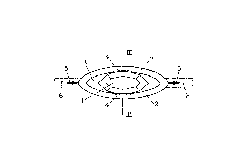
Fig. 1 shows an inventive holder for a gem in a side view,
Fig. 2 shows this holder in a top view, and
Fig. 3 in a section along line lll-lll of Fig. 1.
In accordance with the illustrated embodiment, the holder for a gem 1 consists of
two clamps 2 integrally connected with each other at their ends, which between
each other form a mounting lug 3 for the gem 1. In the longitudinal central portion
of the two clamps 2 the same are provided with clamp recesses 4 disposed op-
posite each other, in which the gem 1 is inserted. For this purpose, the mounting
lug 3 is widened by resiliently spreading apart the two clamps 2, as this is indi-
cated for instance in Fig. 1 by means of the schematically represented spreadingforces 5. When the spreading forces 5 are reduced, the gem 1 introduced in the
mounting lug 3 engages in the clamp recesses 4 with two peripheral portions lo-
cated opposite each other. Because of the remaining bias of the clamps 2, a resil-
ient clamping force acts on the gem 1, which is thus held without any clearance
between the clamps 2, all the more so as the clamp recesses 4 have a cross-
section tapering towards the bottom of the recess, as this can be taken from Fig.
3. The tapered gap formed by this tapering cross-section ensures a safe mountingof the gem 1, without having to provide any additional measures.
The holder with the gem 1 constitutes a separately usable element of jewellery,
which can be used alone or in conjunction with identical elements of jewellery
lined up one beside the other. This element of jewellery can, however, also be
completed to form a web 6, which prolongs the clamps 2 at one or at both ends,
as this is indicated in Fig. 1 in dash-dotted lines. The possible field of use is thus

CA 02262501 1999-02-02
extended, for instance to ear pieces of spectacles, along which at least one such
element of jewellery may be provided.

Representative Drawing
A single figure which represents the drawing illustrating the invention.
Administrative Status

2024-08-01:As part of the Next Generation Patents (NGP) transition, the Canadian Patents Database (CPD) now contains a more detailed Event History, which replicates the Event Log of our new back-office solution.

Please note that "Inactive:" events refers to events no longer in use in our new back-office solution.

For a clearer understanding of the status of the application/patent presented on this page, the site Disclaimer , as well as the definitions for Patent , Event History , Maintenance Fee  and Payment History  should be consulted.

Event History

Description Date
Inactive: Dead - RFE never made 2003-08-07
Deemed Abandoned - Failure to Respond to Maintenance Fee Notice 2003-08-07
Application Not Reinstated by Deadline 2003-08-07
Inactive: Abandon-RFE+Late fee unpaid-Correspondence sent 2002-08-07
Classification Modified 1999-04-06
Inactive: IPC assigned 1999-04-06
Inactive: First IPC assigned 1999-04-06
Inactive: Notice - National entry - No RFE 1999-03-22
Application Received - PCT 1999-03-19
Application Published (Open to Public Inspection) 1998-02-19

Abandonment History

Abandonment Date Reason Reinstatement Date
2003-08-07

Maintenance Fee

The last payment was received on 2002-06-14

Note : If the full payment has not been received on or before the date indicated, a further fee may be required which may be one of the following

  • the reinstatement fee;
  • the late payment fee; or
  • additional fee to reverse deemed expiry.

Patent fees are adjusted on the 1st of January every year. The amounts above are the current amounts if received by December 31 of the current year.
Please refer to the CIPO Patent Fees web page to see all current fee amounts.

Fee History

Fee Type Anniversary Year Due Date Paid Date
Registration of a document 1999-02-02
Basic national fee - standard 1999-02-02
MF (application, 2nd anniv.) - standard 02 1999-08-09 1999-06-30
MF (application, 3rd anniv.) - standard 03 2000-08-07 2000-06-27
MF (application, 4th anniv.) - standard 04 2001-08-07 2001-06-27
MF (application, 5th anniv.) - standard 05 2002-08-07 2002-06-14
Owners on Record

Note: Records showing the ownership history in alphabetical order.

Current Owners on Record
SILHOUETTE INTERNATIONAL SCHMIED GMBH & CO. KG
Past Owners on Record
ANGELA STRECKER
Past Owners that do not appear in the "Owners on Record" listing will appear in other documentation within the application.
Documents

To view selected files, please enter reCAPTCHA code :


To view images, click a link in the Document Description column. To download the documents, select one or more checkboxes in the first column and then click the "Download Selected in PDF format (Zip Archive)" or the "Download Selected as Single PDF" button.

List of published and non-published patent-specific documents on the CPD .

If you have any difficulty accessing content, you can call the Client Service Centre at 1-866-997-1936 or send them an e-mail at CIPO Client Service Centre.


Document
Description 
Date
(yyyy-mm-dd) 
Number of pages   Size of Image (KB) 
Representative drawing 1999-04-18 1 5
Abstract 1999-02-01 1 48
Description 1999-02-01 4 168
Claims 1999-02-01 2 35
Drawings 1999-02-01 1 17
Reminder of maintenance fee due 1999-04-07 1 111
Notice of National Entry 1999-03-21 1 193
Courtesy - Certificate of registration (related document(s)) 1999-03-21 1 117
Reminder - Request for Examination 2002-04-08 1 119
Courtesy - Abandonment Letter (Request for Examination) 2002-10-15 1 169
Courtesy - Abandonment Letter (Maintenance Fee) 2003-09-03 1 176
PCT 1999-02-01 14 477