Note: Descriptions are shown in the official language in which they were submitted.
CA 02262~6~ 1999-02-0~
W0-98155898 PCT/US98111443
RAPID ASSEMBLY PHOTOGRAPHIC LIGHTING DOME
TECHNICAI, FIELD
The present invention relates generally to ilhlmin~tors and more
particularly to apparatus for providing diffused lighting for photographic
purposes. The inventor anticipates that primary application of the present
invention will be for location filming and lighting for mobile broadcast
journalism. However, the present invention is also well suited to use in studio
0 photography and in broadcast Inedia studios.
BACKGROUND ART
~ight diffusion boxes, also known as "softboxes" have long been used by
photographers and camera crews to provide diffused lighting on photographic
subjects. Softboxes are especially useful for location shooting, because they are
generally light-weight and portable. They are generally made collapsible into
compact bundles by using flexible material, such as cloth, which has been
stretched on a light-weight framework. Their use for location filming of news
events by camera crews makes easy and rapid assembly very important. In an
environment where several news crews may be competing for coverage of an
event, or where an unexpected occurrence makes response time crucial, every
second can be valuable to field journalists. The time spent in assembling
lighting equipment for the shooting can make the difference in effectiveness andcompetitive edge.
Unfortunately, prior art softboxes can be clumsy to assemble and often
require a large degree of physical strength. The typical softbox has a flexible
framework which supports and gives shape to a fabric housing which surrounds
. ....
CA 02262~6~ 1999-02-0~
WO- 98/~5898 PCT/US98/11443
a light source. The light source generally must be very bright, from 150 - 500
watts, and thus also produces a great deal of heat. Safety considerations
therefore dictate that the fabric housing be kept well away from the light source,
and not allowed to sag toward it. The supporting structure necessarily stretchesthe fabric tautly, keeping it under tension. The support structure, in collapsible
so~boxes, is typically composed of rods which are flexible along some portion
of their length, and which are captured within seams or channels formed in the
fabric housing. The rods are generally inserted into the channels, which extend
to the four corners of the fabric, and then the free ends are inserted into sockets
] o around the circumference of a rigid central hub. The insertion sockets are
generally straight channels formed into the corners of the hub, into which the
free end of the rod is guided. This often requires that the rod be inserted from a
very small range of approach angles, in order to get the parts to mate properly.The insertion can be difficult, as it involves applying pressure to force the
flexible rods to bend at the same time that the free end is sought to be inserted in
the socket in the central hub. This can require a great degree of physical
strength, as well as much patience since the flexible rods are generally not
designed to be very easily bent, rather to tlle contrary, because they must exert
tension on the fabric housing to insure that it will not sag.
Additionally, the free ends of the support rods sometimes have no sort of
cap structure to blunt the edges of the rod end. There is thus possibility of
injury, if one of the rods slips while the user is seeking to align it with its
insertion socket. If this springy rod with an unblunted edge snaps out straigllt,
this can cc~ dama~.~e to hands, wrists or eyes as the rod can be expected to
straighten ~ .th conslderable force.
U.S. Pat. 4,446,506 to 3,arson discloses a photographic light diffuser with
supporting rods which are placed in metal grommeted apertures in the corners
CA 02262~6~ 1999-02-0~
WO 98/55898 PCT/US98/11443
of panel segments. Assembly is done by first attaching the outer-most corners,
and then attaching the inner-most corners to extending bolts.
U.S. Pat. 4,669,031 to Regester illustrates a light box for photographic
use having flexible rods which are inserted into corner loops of the side walls of
s the housing, forcing them to expand into roughly a truncated pyramidal shape.
At the large end of the housing, each loop is closed to prevent the rod ends from
passing through. This configuration leads to exactly the disadvantages in terms
of convenience and safety which are discussed above.
U.S. Pat. 5,023,756, also to Regester, sllows a light diffusion box with
0 supporting rods which are apparently inserted into the corner edges of a fabric
housing, and then connected at the rod's free ends to a central ring structure. As
in the previous Regester patent, this configuration has the precise defects which
are enumerated above, and which are addressed in the present invention. In
addition, the multi-part rods used have ends which are not interchangeable,
which slows assembly.
There is thus a need for an improved light diffusing box which is
collapsible, and which assembles and disassembles in a rapid, easy and safe
manner.
DISCLOSURE OF THE INVENTION
Accordingly, it is an object of the present invention to provide a
photographic lighting dome which can be rapidly assembled.
Another object of the present invention is to provide a photographic
25 lighting dome which requires very little physical strength to assemble.
Another object of the present invention is to provide a photographic
lighting dome in which application and release of spring tension to the support
rods can be done in a safe and controlled manner.
CA 02262~6~ 1999-02-0~
WO 98/55898 PCT/US98/11443
Briefly, one preferred embodiment of the present invention is a
photographic lighting dome for holding and directing a light source, the lighting
dome having a housing of flexible material. The housing has an inner perimeter
5 surrounding a central opening, and an outer perimeter. The lighting dome also
includes a number of flexible support rods, each rod having a connecting end
and a releasable end, and a central hub positioned in the central opening of thehousing. This hub has a number of support rod attachment fixtures, each fixture
configured for receiving the connecting end of one of the support rods. A
lo number of channels are formed in the housing, extending from the housing
central opening to the outer perimeter of the housing, each channel being shapedto receive one of the support rods. Each channel has two ends and an opening at
each of the ends. There is a central channel opening to allow the connecting
end of a support rod to pass through for attachment to the central hub, and an
15 outer perimeter channel opening, through which the releasable end of the
support rod passes. A number of retainers are attached near the housing
perimeter for releasably capturing the support rods. The axial force is
maintained in each of said support rods in the channels while the retainers are
fastened, but the rods are controllably released in the direction of the outer
20 perimeter when the retainers are unfastened.
An advantage of the present invention is that the assembly of the
photographic lighting dome can be done very rapidly.
Another advantage of the prest~ ~t invention is that the retaining tabs at
25 each corner o~ the housing can be easily fastened or released while the support
rods are under tension.
Yet another advantage of the present invention is that very little physical
strength is required to assemble the photographic lighting dome.
CA 02262.76.7 1 999 - 02 - 0.,
WO 98/55898 PCT/US98/11443
Still another advantage of the present invention is that the retaining tabs
allow a controlled application and release of spring tension to the support rods,
allowing for improved control.
A yet further advantage of the present invention is that the present
5 invention is much safer to use, due to the increased control of spring tension in
the rods, and the inclusion of safety tips on the rods.
An additional advantage of the present invention is that the rods are
completely reversible, which allows for high-speed assembly, relative to prior
art lighting boxes.
These and other objects and advantages of the present invention will
become clear to those skilled in the art in view of the description of the best
presently known mode of carrying out the invention and the industrial
applicability of the preferred embodiment as described herein and as illustrateds in the several figures of the drawings.
BRIEF DESCRIPTION OF THE DRAWINGS
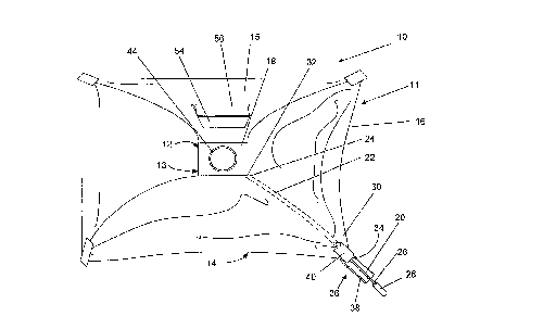
FIG. 1 is a top plan view of the improved dome structure for rapid
20 assembly of the present invention; and
FIG. 2 is a top plan view of the central hub, with all connecting rods and
the housing removed.
BEST MODE FOR CARRYING OUT THE INVENTION
A preferred embodiment of the present invention is a photographic
softbox in the form of a light dome particularly adapted for rapid assembly.
CA 02262~6~ 1999-02-0~
W0-98/55898 PCT/USg8/11443
As illustrated in the various drawings herein, and particularly in the view
of FIG. 1, a form of this preferred embodiment of the inventive device is
depicted by the general reference character 10.
FIG. 1 illustrates the light dome 10 including a housing 11 having an
s inner perimeter 12 which surrounds a central opening 13. The housing 11 also
has an outer perimeter 14. In this embodiment, the housing 11 has two long
sides 15 and two short sides 16 to produce a rectangular f1eld of illumination.
This allows the dome 10 to be oriented with a long side 15 turned horizontally
for illumination of"landscape" style field of view, or to have a short side 16
o oriented horizontally for "portrait" style images. It should be understood,
however that the dome could be made with four equal sides to make a square
structure, or it could have fewer sides, such as three, or more sides such as five,
six or eight, etc. The dome 10 further has a central hub 18 positioned within the
central opening 12, and a plurality of support rods 20. The support rods 20 are
S enclosed in seams or channels 22 (only one is shown in the figure) provided inthe edges of the housing 11, and are made to slide within the channels 22 so that
they may be easily inserted or removed from the channels 22. The support rods
20 are fungible and are formed of material such as flexible metal or fiberglass
and have a connecting end 24 which will engage the central hub 18, and a
20 releasable end 26 which is covered with a protective foot 28. The channels 22of the housing 11 are open at both ends, with one opening near the central hub
18, and one at a corner of the housing 30. For ease of reference, these shall becalled the center opening 32 and the perimeter opening 34, respectively. It
should be understood that it is possible to practice the present invention where2s there is no center opening in the channel, so that the support rod connecting end
is stopped from further axial movement by a blind end to the channel. These
blind ends could be near the central opening, but not connecting to it, and could
act as an alternative to connecting to a central hub.
CA 02262~6~ 1999-02-0~
WO 98/55898 PCT/US98/11443
Each housing corner 30 has a securing assembly 36 which includes a
retaining tab 38 and a fastener 40. In this version of the preferred embodiment,the retaining tab 38 and fastener 40 are a hook and eye mechanism such as
Velcro~M, but it should be understood that many other varieties of fasteners,
5 such as buttons, snaps, zippers and latches, among others, may be used to secure
the retaining tab 38 to the fastener 40. It should also be understood that if
VelcroTM is used, either the hook or the eye portion of the VelcroTM fastener
may be placed on tlle retaining tab 38 to engage the corresponding eye or hook
portion on the fastener 40. Similarly, the placement of other fasteners may be
o similarly reversed, for example a button may be on either the retaining tab 38 or
the fastener 40 to cooperate witl1 a corresponding buttonhole.
FIG. 2 shows the central hub 18 with the housing and the support rods
removed. The central hub 18 includes a plurality of rod attachment fixtures 42,
which in this version of the preferred embodiment are unthreaded insertion
15 sockets 46, but which could be a number of other mechanisms, such as clamps,
retaining pins, screws or threaded sockets into whicl1 support rods 20 with
tapped screws threads may be fixed. The central hub 18, in this version of the
preferred embodiment is basically a rectangle and the attachment fixtures 42 arelocated at the four corners of the central hub 18. This version of the preferred20 embodiment also has been formed with one of the insertion sockets 46 of the
attachment fixture 42 having a portion with a slightly larger diameter near its
opening. This aids in assembly of the light dome 10, by providing a larger
aperture for insertion of the rod 20, thus making the approach angle for inserting
the support rod 20 less limited. This insertion socket 46 with the enlarged
25 aperture is marked with an identifying symbol 48. The connecting end 24 of the
support rod 20 is provided with a cap ~0 which is appropriately sized for properfit in the insertion socket 46. This also has the advantage of providing safety
protection from unblunted edges of the underlying support rod 20 connecting
CA 02262~6~ 1999-02-0~
W~ 98/55898 PCT/US98/11443
end 24. It should be understood that the use of these caps is opt~onal and the
invention can be practiced using rods 20 of suitable diameter without these caps,
and also without the protective feet 28 at the releasable end 26 of the rods 20.This version of the preferred embodiment also has an alternate set of
5 connecting sockets 52 which can be used to support alternate housings or the
standard housing 11 in an alternate manner.
Referring now to both Figs. 1 and 2, assembly can be performed by
inserting the connecting end 24 of the rod 20 with its end cap 50 into the
channel corner opening 34 of a channel 22 of the housing 11, and sliding it in
lo the channel 22 until the rod's connecting end 24 emerges from the center
opening 32 of the channel 22. Alternately, the releasable end 26 of the rod 20
with its protective foot 28 can be inserted into the center opening 32 of a
channel 22 and the rod 20 pushed until the foot 28 emerges from the perimeter
opening 34 of the channel 22. This is repeated for the other rods 20 until all
5 have been inserted. The rod end caps 50 of the connecting ends 24 of the rods
20 are then inserted into the insertion sockets 46 of the rod attachment fîxtures
42. The releasable ends 26 of the rods 20 thus protrude from the corners 30 of
the housing 11. Pressure is then applied to the releasable ends 26 in an axial
direction to force the rods 20 into the channels 22, causing them to bow in
20 conformance to the arcs defined by the channels 22 within the housing 11
shape. When a releasable end 26 has been pushed into the corner opening 34 of
a channel 22, the retaining tab 38 of the securing assembly 36 is pulled up to
engage the fastener 40. This is repeated with the other support rods 20 to
complete assembly o~ ~e housing 11. Alternately, the rod 20 can be pushed
25 into the channel 22 just far enough that the foot 28 contacts a portion of the
retaining tab 38. The tab 38 can then be pulled up to engage the fastener 40, atthe same time acting as a small pulley to force the rod's releasable end 26
completely into the channel corner opening 34.
CA 02262~6~ 1999-02-0~
WO g8/55898 PCT/US98/11443
Disassembly can be done by reversing the above steps, starting with
disengaging one of the retaining tabs 38 from its corresponding fastener 40 to
allow the rod 20 to straighten.
Alternatively, assembly can be done by fastening the releasable ends 26
of the rods 20 in the corners 30 first, and then inserting the rod connecting ends
24 into the insertion sockets 46 of the attachment fixtures 42, in effect using the
method required by the prior art. Comparing this prior method with the
improved method made possible by the present invention makes it clear the
advantage which the present invention holds. If, however, the prior method is
o to be used, the present invention also allows an improvement in assembly which
is accomplished by inserting the rod connecting end 24 into the insertion socket46 marked with the identifying symbol 48 as the last connection, which
typically requires the most force and skill in alignment. The enlarged aperture
of the marked insertion socket 46 makes alignment easier to accomplish.
Conversely, for disassembly, the marked socket 46 should be disengaged from
its respective rod 20 first, as the enlarged aperture allows less force to be
exerted on the rod 20 and removal alignment is also less critical.
The central hub further includes a light source attachment f;xture 44 with
a variety of mounting points to which a light source (not shown) can be
attached.
Referring again to Fig. 1, the housing 11 also has a plurality of ventilation
ports 54 which are covered by reclosable flaps 56. These ventilation ports 54
can be opened to allow cooling air from the base to flow in a chimney-like
fashion which aids in cooling the light source.
Although not shown in the figures, it should be understood that the
present lighting dome 10 also includes one or more light deflecting or
transmitting panels or screens which serve to diffuse light from the light source
in a standard manner.
. .
CA 02262~6~ 1999-02-0~
WO 98/55898 PCT/US98/11443
--10-
In addition to the above mentioned examples, various other modifications
and alterations of the inventive device 10 may be made without departing from
the invention.
s INDUSTRIAL APPLICABILITY
The present photographic lighting dome 10 is well suited for providing
diffused lighting for photographic purposes. The inventor anticipates that
primary application of the present invention will be for location filming and
lo lighting for mobile broadcast journalism. However, the present invention is also
well suited to use in studio photography and in broadcast media studios.
Collapsible lighting domes which are covered with cloth are also known
as "softboxes". They are generally made to be collapsible into compact bundles
which are easily portable for photograpl1ic purposes in field locations. Because5 they are so portable, their use by camera crews has increased dramatically in
recent years. News camera crews are known for their competitiveness in
covering newsworthy events, arld the competitive edge of a crew depends on
being able to respond quickly to breaking events. Thus any advance which can
speed the set-up time re~uired for assembling photograpllic equipment can be of
20 immense value in the race to cover a news story. The present invention 10
speeds the set-up time by presenting a softbox which is much quicker and easier
to assemble.
Assembly can be performed by inserting the connecting end 24 of the
rod 20 with its end cap 50 into the channel . -rner - pening 34 of a channel 22 of
25 the housing 11, and sliding it in the channel 22 until the rod's connecting end 24
emerges from the center opening 32 of the channel 22. Alternately, the
releasable end 26 of the rod 20 with its protective foot 28 can be inserted intothe center opening 32 of a channel 22 and the rod 20 pushed until the foot 28
CA 02262~6~ 1999-02-0~
WO 98155898 PCT/US98/11 443
emerges from the corner opening 34 of the channel 22. This is repeated for the
other rods 20 until all have been inserted. The rod end caps 50 of the
connecting ends 24 of the rods 20 are then inserted into the insertion sockets 46
of the rod attachment fixtures 42. The releasable ends 26 of the rods 20 thus
5 protrude from the corners 30 of the housing 11. Pressure is then applied to the
releasable ends 26 in an axial direction to force the rods 20 into the channels 22,
causing them to bow in conformance to the arcs defined by the channels 22
within the housing 12 shape. When a releasable end 26 has been pushed into
the corner opening 34 of a channel 22, the retaining tab 38 of the securing
o assembly 36 is pulled up to engage the fastener 40. This is repeated with the
other support rods 20 to complete assembly of the housing 11. Alternately, the
rod 20 can be pushed into the channel 22 just far enough that the foot 28
contacts a portion of the retaining tab 38. The tab 38 can then be pulled up to
engage the fastener 40, at the same time acting as a small lever to push the rod's
15 releasable end 26 completely into the channel corner opening 34.
Disassembly can be done by reversing the above steps, starting with
disengaging one of the retaining tabs 38 from its corresponding fastener 40 to
allow the rod 20 to straighten.
Prior art softboxes typically require that the central end of the rod be
20 directed into a hole in the central hub while the rods are under axial
compression. The holes are generally of small diameter and require that the
rods enter within a small range of approach angles, which can be rather like
threading a needle while simultaneously compressing a spring. If this springy
rod witl1 a typically unblunted edge snaps out straight, this can cause ~l~m~ge to
2~ hands, wrists or eyes as the rod can be expected to straighten with considerable
force.
In contrast, the present invention 10 is not only quicker to assemble, but it
also requires less physical strength and fine coordination. Tl~e connecting ends
CA 02262~,6~, 1999-02-0~
W0-98/S5898 PCT/US98/1 1443
24 of the support rods 20 are inserted into the hub 18 first, wl ile there is notension in the rods 20, and the corner ends 34 of the housing 11 only require that
the retaining tabs 38 be pulled up to meet the fasteners 40. Additionally, as
stated above, the ret~ining tabs 38 can be used to provide leverage. The present5 invention 10 is thus much safer to use, as well as being faster and easier to
assemble. This enhanced safety makes the present invention also advantageous
for uses in which speed of assembly is not crucial, such as in photographic
studios, broadcast studios and even for home photography.
For the above and other reasons, it is expected that the rapid assembly
o photographic lighting dome 10 ofthe present invention will have widespread
industrial applicability. Therefore, it is expected that the commercial utility of
the present invention will be extensive and long lasting.