Language selection

Search

Patent 2262810 Summary

Third-party information liability

Some of the information on this Web page has been provided by external sources. The Government of Canada is not responsible for the accuracy, reliability or currency of the information supplied by external sources. Users wishing to rely upon this information should consult directly with the source of the information. Content provided by external sources is not subject to official languages, privacy and accessibility requirements.

Claims and Abstract availability

Any discrepancies in the text and image of the Claims and Abstract are due to differing posting times. Text of the Claims and Abstract are posted:

  • At the time the application is open to public inspection;
  • At the time of issue of the patent (grant).
(12) Patent: (11) CA 2262810
(54) English Title: A SEAL DEVICE
(54) French Title: DISPOSITIF D'ETANCHEITE
Status: Term Expired - Post Grant Beyond Limit
Bibliographic Data
(51) International Patent Classification (IPC):
  • F16J 15/40 (2006.01)
  • F04D 03/00 (2006.01)
  • F04D 29/12 (2006.01)
  • F16J 15/34 (2006.01)
(72) Inventors :
  • ARBEUS, ULF (Sweden)
(73) Owners :
  • ITT MANUFACTURING ENTERPRISES, INC.
(71) Applicants :
  • ITT MANUFACTURING ENTERPRISES, INC. (United States of America)
(74) Agent: SMART & BIGGAR LP
(74) Associate agent:
(45) Issued: 2003-04-29
(22) Filed Date: 1999-02-24
(41) Open to Public Inspection: 1999-08-25
Examination requested: 1999-02-24
Availability of licence: N/A
Dedicated to the Public: N/A
(25) Language of filing: English

Patent Cooperation Treaty (PCT): No

(30) Application Priority Data:
Application No. Country/Territory Date
9800553-1 (Sweden) 1998-02-25

Abstracts

English Abstract

The invention concerns a seal device for a submersible machine, such as a pump or a mixer. The seal device is designed as an easily replaceable unit comprising two mechanical face seals (4,6) and (5,7) resp, parted by a room for a barrier liquid in which a pump impeller (10) is located, said impeller circulating the barrier liquid passing it along the seals and through cooling channels in the driving unit of the machine.


French Abstract

L'invention porte sur un dispositif d'étanchéité pour une machine submersible, comme une pompe ou un mélangeur. Le dispositif d'étanchéité est conçu comme une unité facilement remplaçable comprenant deux joints mécaniques (4,6) et respectivement (5,7), séparés par une enceinte pour un liquide barrière dans lequel un rotor de pompe (10) est situé, ledit rotor faisant circuler le liquide barrière en le passant le long des joints et dans des canaux de refroidissement dans l'unité motrice de la machine.

Claims

Note: Claims are shown in the official language in which they were submitted.

4
CLAIMS:
1. A seal device in the form of an easily
exchangeable unit for a rotary driving shaft between an
electric motor and a hydraulic unit, the seal device
comprising:
two mechanical face seals with an intermediate
room for a barrier liquid that also serves as a cooling
medium for an associated electric motor; and
a pump for circulating the barrier liquid, the
pump being a half axial or axial type, the pump including:
an impeller of a half axial or axial type having a
plurality of vanes, the impeller to be attached on the
driving shaft;
a first group of stationary guide vanes located
upstream of the impeller; and
a second group of stationary guide vanes located
downstream of the impeller.
2. A seal device according to claim 1, wherein the
face seals include stationary seal rings and the pump
further includes a holding device which supports the
stationary seal rings, the holding device forming a cavity
which contains the impeller.
3. A seal device according to claim 1, wherein the
first group of stationary guide vanes located upstream of
the impeller are linked so that a counter rotation of the
barrier liquid is obtained, thereby increasing the head.

Description

Note: Descriptions are shown in the official language in which they were submitted.


ARBEUS-15
A SEAL DEVICE
The present invention concerns a device for a submersible machine, such as a
pump, a turbine or a mixer.
A machine of this type normally includes an electrically driven motor and a
hydraulic
unit with an impeller connected to the motor via a rotary driving shaft.
In order to prevent the medium within the hydraulic unit from flowing along
the shaft
and penetrate the electric motor and cause damage, one or several seals are
arranged between the motor and the hydraulic unit. A common type of seal is
the
so-called mechanical face seal, which comprises one seal ring rotating with
the shaft
and one stationary seal ring mounted in the surrounding housing. The two rings
are
pressed together by spring force thus preventing medium from penetrating
between
them.
If the medium within the hydraulic unit contains pollutants, a special problem
occurs.
As the pressure within the hydraulic unit is higher, pollutants may penetrate
between
the seal surfaces an cause damage, meaning that the seal result is worsened or
fails
totally.
In order to solve this problem it is common to arrange two mechanical seals
parted
by a room filled with a barrier liquid such as oil, which lubricates and cools
the
surfaces. By this the seal adjacent the electric motor will always operate
with a clean
medium and thus the risks for damages will decrease drastically. If the seal
adjacent
the hydraulic unit should be damaged, medium from said unit may enter the
barrier
liquid room, but by controlling said liquid at regular intervals, the seal
could be
repaired or replaced before any serious damage has accured. An example on such
a
design is shown in the Swedish patent No 381 318.
If it has been noted that the barrier liquid has been too diluted by the
medium in the
hydraulic unit, the seal adjacent said unit must be replaced. If the dilution
has been
considerable, there is a risk that also the other seal has been damaged and
therefore it might be preferable to replace both seals at the same time.
CA 02262810 1999-02-24

CA 02262810 2002-08-O1
72432-115
2
In order to make such a replacement: easier to
obtain, it has been suggested to bui:Lci them together into a
unit which makes service easier and increased> the
reliability. Examples on such designs are shown in the
Swedish patents 200 144 and 466 925. In order to obtain a
good circulation of the barrier liquid within the seal unit,
it has been suggested to arrange a pump within the latter.
Especially in a case where it has been chosen to use a
closed cooling system f=or the electric. motor using the
barrier liquid as cooling medium, a pump is necessary if a
sufficient flow should be obtained. Known de:sign.s such as
those shown in the Swedish patent 32'7 904 have however
certain disadvantages concerning space demand. and
efficiency.
This invention concerns a device which in an
effective and secure way obtains the necessary circulation
even at a low rotation speed and which has a very limited
space demand.
The invention may be summarised as a seal device
in the form of an easily exchangeable unit for a rotary
driving shaft between an electric motor and a hydraulic
unit, the seal device comprising: two mechanical face seals
with an intermediate room for a barrier liquid that also
serves as a cooling medium for an associated electric motor;
and a pump for circulating the barrier liquid, the pump
being a half axial or axial type, the pump including: an
impeller of a half axial or axial type having a plurality of
vanes, the impeller to be attached on the driving shaft; a
first group of stationary guide vanes located upstream of
the impeller; and a second group of stationary guide vanes
located downstream of the impeller.

CA 02262810 2002-08-O1
72432-115
2a
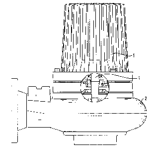
The invention is disclosed more closely below with
reference to the enclosed drawings. F.ig. 1 shows a cut
through a pump unit provided with a seal arrangement
according to the invention, while Fig. 2 shows a part of a
circulation pump within the seal device.
In the drawings 1 stands far a driving unit, 2 a
hydraulic unit and 3 a driving shaft between the two. 4 and
5 stand for rotary seal rings and 6 and '7 stationary seal
rings supported in a common holder 8, the latter provided
with a cavity 9. 10 stands for an axial pump impeller
having vanes 11. 12 and 13 stand for stationary guide vanes
and 14 and 15 finally connections for cowling liquid.
The driving shaft 3 between the driving unit 1 and
the hydraulic unit 2. is thus sealed by help of a mechanical
seal arrangement 4, 6 and 5, 7. The seal.. rings 4 and 5
rotate with the shaft 3 and are pressed towards the
stationary seal rings 6 and 7 respectively by spring force.
In this way liquid within the hydraul:i.c unit is prevented
from entering the driving unit along the shaft.
As previously mentioned, the invention concerns a
solution where a circulation pump is :i.ntegrated in a seal
arrangement, the pump circulating the barrier liquid in said
seal arrangement, and where, according t.a a special
embodiment, the barrier- liquid also serves as cooling medium
for the driving unit. The cavity or c-_;hannel 9 within the
seal arrangement which contains the impeller of said pump,
being connected to cooling channels ian the driving unit via
ports 14 and 15.

3
In the designs used up to now, a centrifugal pump impeller with a low specific
rotation speed is used where the static head cannot be utilized hPCamP
insufficiant sealing. The efficiency of such a pump is therefore extremely
low, around
5%. The flow obtained will therefore be almost entirely laminar which results
in quite
a low heat exchange rate in the cooling channels of the driving unit.
The relation between flow losses and actual geometric conditions in a
submersible
pump means, that the best heat exchange is obtained by a pump having a high
specific rotation speed. This is very important in order to secure a turbulent
flow
which is superiour for a good heat exchange.
According to the invention the turbulent flow is obtained even at relatively
low
rotation speeds as the pump is designed as a half axial or axial type pump in
the
following way:
The pump inlet is provided with a number of guide vanes 12 which generate a
counter rotation which increases the head. The pump impeller 10, which is
attached
to the driving shaft 3, is a highly loaded half axial or axial type impeller,
having a
number of vanes which rotate in the channel 9. After a radial linking, the
liquid finally
passes a number of diffusing guide vanes 13. In this way a design is obtained
which
is characterized by being very compact. Especially the radial space demand is
very
limited.
Thanks to the design of the pump with a highly loaded pump impeller, guide
vanes
and well sealed connections, a very high specific rotation speed is obtained,
which
creates a turbulent flow of the barrier liquid/cooling medium even at
relatively low
rotation speeds. A turbulent flow is, as previously mentioned, a condition if
a good
heat exchange should be obtained if the volume is limited. The latter is
necessary as
the power needed for the circulation must be very low in order not to reduce
the total
efficiency of the machine.
In the description has been referred to a mechanical face seal arrangement,
where
the integrated pump circulates barrier liquid which also serves as a cooling
liquid for
the driving motor of the machine. The invention is however not limited to this
embodiment, but is also possible to apply when the cooling is obtained by help
of a
liquid other than the barrier liquid.
CA 02262810 1999-02-24

Representative Drawing
A single figure which represents the drawing illustrating the invention.
Administrative Status

2024-08-01:As part of the Next Generation Patents (NGP) transition, the Canadian Patents Database (CPD) now contains a more detailed Event History, which replicates the Event Log of our new back-office solution.

Please note that "Inactive:" events refers to events no longer in use in our new back-office solution.

For a clearer understanding of the status of the application/patent presented on this page, the site Disclaimer , as well as the definitions for Patent , Event History , Maintenance Fee  and Payment History  should be consulted.

Event History

Description Date
Inactive: Expired (new Act pat) 2019-02-24
Change of Address or Method of Correspondence Request Received 2018-03-28
Inactive: Late MF processed 2007-03-19
Letter Sent 2007-02-26
Inactive: IPC from MCD 2006-03-12
Grant by Issuance 2003-04-29
Inactive: Cover page published 2003-04-28
Pre-grant 2003-02-05
Inactive: Final fee received 2003-02-05
Notice of Allowance is Issued 2002-12-06
Letter Sent 2002-12-06
Notice of Allowance is Issued 2002-12-06
Inactive: Approved for allowance (AFA) 2002-11-28
Inactive: IPC assigned 2002-11-08
Amendment Received - Voluntary Amendment 2002-08-01
Inactive: S.30(2) Rules - Examiner requisition 2002-04-29
Amendment Received - Voluntary Amendment 2001-11-27
Application Published (Open to Public Inspection) 1999-08-25
Inactive: Cover page published 1999-08-25
Inactive: IPC assigned 1999-04-21
Inactive: First IPC assigned 1999-04-21
Classification Modified 1999-04-21
Inactive: Filing certificate - RFE (English) 1999-03-23
Application Received - Regular National 1999-03-22
Request for Examination Requirements Determined Compliant 1999-02-24
All Requirements for Examination Determined Compliant 1999-02-24

Abandonment History

There is no abandonment history.

Maintenance Fee

The last payment was received on 2002-10-15

Note : If the full payment has not been received on or before the date indicated, a further fee may be required which may be one of the following

  • the reinstatement fee;
  • the late payment fee; or
  • additional fee to reverse deemed expiry.

Patent fees are adjusted on the 1st of January every year. The amounts above are the current amounts if received by December 31 of the current year.
Please refer to the CIPO Patent Fees web page to see all current fee amounts.

Owners on Record

Note: Records showing the ownership history in alphabetical order.

Current Owners on Record
ITT MANUFACTURING ENTERPRISES, INC.
Past Owners on Record
ULF ARBEUS
Past Owners that do not appear in the "Owners on Record" listing will appear in other documentation within the application.
Documents

To view selected files, please enter reCAPTCHA code :


To view images, click a link in the Document Description column (Temporarily unavailable). To download the documents, select one or more checkboxes in the first column and then click the "Download Selected in PDF format (Zip Archive)" or the "Download Selected as Single PDF" button.

List of published and non-published patent-specific documents on the CPD .

If you have any difficulty accessing content, you can call the Client Service Centre at 1-866-997-1936 or send them an e-mail at CIPO Client Service Centre.

({010=All Documents, 020=As Filed, 030=As Open to Public Inspection, 040=At Issuance, 050=Examination, 060=Incoming Correspondence, 070=Miscellaneous, 080=Outgoing Correspondence, 090=Payment})


Document
Description 
Date
(yyyy-mm-dd) 
Number of pages   Size of Image (KB) 
Abstract 1999-02-23 1 12
Description 1999-02-23 3 159
Claims 1999-02-23 1 29
Drawings 1999-02-23 2 25
Description 2002-07-31 4 201
Claims 2002-07-31 1 38
Drawings 2001-11-26 2 22
Representative drawing 2002-04-07 1 12
Representative drawing 1999-08-24 1 11
Courtesy - Certificate of registration (related document(s)) 1999-03-22 1 117
Filing Certificate (English) 1999-03-22 1 165
Reminder of maintenance fee due 2000-10-24 1 110
Commissioner's Notice - Application Found Allowable 2002-12-05 1 160
Maintenance Fee Notice 2007-04-09 1 172
Late Payment Acknowledgement 2007-04-12 1 165
Correspondence 2003-02-04 1 34