Language selection

Search

Patent 2263209 Summary

Third-party information liability

Some of the information on this Web page has been provided by external sources. The Government of Canada is not responsible for the accuracy, reliability or currency of the information supplied by external sources. Users wishing to rely upon this information should consult directly with the source of the information. Content provided by external sources is not subject to official languages, privacy and accessibility requirements.

Claims and Abstract availability

Any discrepancies in the text and image of the Claims and Abstract are due to differing posting times. Text of the Claims and Abstract are posted:

  • At the time the application is open to public inspection;
  • At the time of issue of the patent (grant).
(12) Patent Application: (11) CA 2263209
(54) English Title: PROTECTIVE SECOND BOOT FOR CONNECTABLE COMPONENTS, FOR PREVENTING ACCIDENTS INVOLVING DRIVELINES INCORPORATING SHAFTS WITH UNIVERSAL JOINTS OR THE LIKE
(54) French Title: SECOND CAPOT DE PROTECTION POUR COMPOSANTS POUVANT ETRE ACCOUPLES, CONCU POUR EMPECHER LES ACCIDENTS IMPLIQUANT LES CHAINES CINEMATIQUES DOTEES D'ARBRES A JOINTS UNIVERSELS OU SIMILAIRE
Status: Deemed Abandoned and Beyond the Period of Reinstatement - Pending Response to Notice of Disregarded Communication
Bibliographic Data
(51) International Patent Classification (IPC):
  • F16D 03/84 (2006.01)
  • A01B 71/08 (2006.01)
  • F16P 01/02 (2006.01)
(72) Inventors :
  • BONDIOLI, EDI (Italy)
(73) Owners :
  • EDI BONDIOLI
(71) Applicants :
  • EDI BONDIOLI (Italy)
(74) Agent: SMART & BIGGAR LP
(74) Associate agent:
(45) Issued:
(86) PCT Filing Date: 1997-07-28
(87) Open to Public Inspection: 1998-02-19
Availability of licence: N/A
Dedicated to the Public: N/A
(25) Language of filing: English

Patent Cooperation Treaty (PCT): Yes
(86) PCT Filing Number: PCT/IT1997/000189
(87) International Publication Number: IT1997000189
(85) National Entry: 1999-02-12

(30) Application Priority Data:
Application No. Country/Territory Date
FI96A000198 (Italy) 1996-08-14

Abstracts

English Abstract


The second boot that protects parts adjacent to a fixed box from which there
projects a rotating hub that is to be connected to a driveline (with the
possible presence of a friction clutch or of a torque limiting means)
comprises - attached to the fixed box (1) - a disc (11) with a peripheral edge
(11A) for engagement and fastening; and a sleeve (17) that can be engaged
inside the edge (11A-11B) of said disc (11), with fastening clips (22) capable
of being clipped to and unclipped from said edge (11A-11B). Said sleeve (17)
may include protective layers around the parts which it encloses.


French Abstract

Le second capot qui protège des parties adjacentes à une boîte fixe depuis laquelle un moyeu rotatif à relier à une chaîne cinématique (un embrayage à friction ou un moyen limiteur de couple étant éventuellement présent) comporte: fixée à la boîte fixe (1), un disque (11) dont le bord périphérique (11A) permet l'emboîtement et la fixation; un manchon (17) qui peut s'engager dans le bord (11A-11B) dudit disque (11), des moyens d'attache (22) pouvant être fixés sur ledit bord (11A-11B) et en être enlevés. Ledit manchon (17) peut comporter des couches de protection autour des parties qu'il entoure.

Claims

Note: Claims are shown in the official language in which they were submitted.

-6-
CLAIMS
1. A protecting boot for protecting parts adjacent
to a fixed box from which there projects a rotating hub
that is to be connected to a driveline incorporating a
jointed shaft with its protective covering, said boot
including: attached to the fixed box (1) a disc (11) with
a peripheral edge (11A) for engagement and fastening; and
a sleeve (17) that can be engaged inside the edge (11A)
of said disc (11) with fastening clips (22) capable of
being clipped to and unclipped from said edge (11A).
2. The boot according to Claim 1, wherein said
sleeve (17) comprises a tubular skirt (19) having
flexible portions and made of a synthetic material.
3. The boot according to Claim 1 or 2, including in
the disc (11) ventilation apertures, with deformations
(13A) that function in conjunction with the passage
defined between the sleeve (17) and a further protective
boot (9B) that surrounds a universal joint of the
driveline, these deformations tending to limit any
deforming of said skirt.
4. The boot according to Claim 2, including on the
inside of said tubular skirt (19) a tubular layer (30)
with insulating properties, and a tubular sheet metal
piece (32) for reinforcement on the inside.
5. The boot according to Claim 2, wherein said
tubular layer (30) and said tubular sheet metal piece
(32) are both bent strips held in place by locking rings
(34) housed in channels formed in the sheet metal piece.
6. The boot according to one or more of the
preceding claims, including a connecting chain (24)
between said disc (11) and said sleeve (17) and a chain
(26), with a clip, between said disc (11) and a
protective sheath (9A) of the jointed drive shaft.
7. The boot according to one or more of the preceding
claims, for a driveline including a friction clutch or a
torque limiting means or other member.
8. The boot according to one or more of the preceding

-7-
claims, wherein said sleeve (17) includes protective
layers around the parts which it encloses.

Description

Note: Descriptions are shown in the official language in which they were submitted.


CA 02263209 1999-02-12
W O 98/06955 PCT~T97/00189
Protective second boot for connectable components, for
preventing accidents involving drivelines incorporating
shafts with universal joints or the like
DESC~IP~IO~
The invention relates to an improved second boot
for protecting parts adjacent to a fixed box from which
there projects a rotating hub that is to be connected to
a driveline incorporating a shaft with universal or other
joints and with its own protection, with the possible
presence of a friction clutch or of a torque limiting
means or other member. Among the objects of the
invention, which will be understood on reading the
following text, are ease of access for operations on the
parts inside, ease of dismantling and so forth.
The second boot according to the invention
basically comprises: attached to the fixed box, a disc
with a peripheral edge for engagement and fastening; and
a sleeve that can be engaged inside the edge of said disc
with fastening clips capable of being clipped to and
unclipped from said edge. Said sleeve may include
protective layers around the parts which it encloses.
In practice, said sleeve may comprise a tubular
skirt having flexible portions and made from a relatively
flexible synthetic material.
Advantageously provided in the disc are
ventilation apertures, with deformations that function in
conjunction with the passage defined between the sleeve
and the protective boot surrounding the universal joint
of the driveline; the deformations also tend to limit any
deforming of said skirt.
On the inside of said tubular skirt there may a
tubular layer with insulating properties, and a tubular
sheet metal piece for reinforcement from the inside of
said tubular layer. The tubular layer and said tubular
sheet metal piece may both be bent strips held in place
by locking rings housed in channels formed in the sheet

CA 02263209 1999-02-12
W O 98/06955 PCT~T97tO01~9
2 -
metal piece.
The second boot to which the invention relates
may advantageously comprise a connecting chain between
said disc and said sleeve and a chain, with a clip,
between said disc and the protective sheath of the
jointed drive shaft.
A clearer understanding of the invention will be
gained from the description and accompanying drawing,
which latter shows a practical, non-restrictive example
of the invention. In the drawing, at different scales:
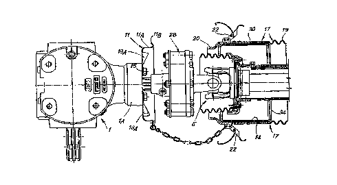
Figs. 1 and 2 show the assembly in a side view
and partial section with certain components separated in
Fig. 1 and assembled in Fig. 2;
Figs. 3, 4 and 5 show certain components in
isolation, Fig. 5 being a section on V-V as marked in
Fig. 4;
Figs. 6 and 7 correspond to Figs. 1 and 2 and
show an embodiment that has been modified to also include
a friction clutch or equivalent torque limiting means;
Fig. 8 is a perspective view of the components of
a reinforced sleeve; and
Figs. 9, 10 and 11 show the second boot as
mounted, in a partial axial view, in the section on X-X
as marked in Fig. 9 and in an enlarged detail of the
portion indicated ~y arrow fll in Fig. 10.
As depicted in Figs. 1 to 5, the numeral 1 is a
general reference for a power take-off box, extending
from a portion lA of which is a power take-off 3
consisting of a short projecting splined shaft, similar
to shaft 3A which also projects from the box 1. Engaged
on the power take-off 3 in the drawing is the fork 5~ of
a universal joint 5, whose second fork 5B is combined
with a telescopic shaft 7 of a driveline that includes
two universal joints, of a type that is known, especially
in agricultural machinery, and as such fitted with a
protective covering formed by a telescopic sheath 9A and
by a boot 9B to protect the universal joint 5. The
invention relates to a second boot which is fitted

CA 02263209 1999-02-12
PCT~T97100189
W098/069~5
3 - _
conventionally to portion lA of the box 1 to surround the
joint 5 and also to overlap around the first boot 9B of
the aforesaid protective covering 9A, 9B.
As shown in the drawing, a disc 11 with a
5 basically cylindrical edge llA terminating in an outward
turned-back lip llB is attached to the end face of the
portion lA of the ~ox 1 (the portion from which the power
take-of~ 3 projects). The disc 11 has a series of windows
in its flat central area partly for the exit of the power
lo take-of~ shaft 3, and partly for its attachment by means
o~ bolts to the end surface of the portion lA, adapting
it to the different dimensions of commercially available
boxes; furthermore, and characteristically, said disc 11
has ventila~ion apertures 13 which are made by slitting
15 the sheet metal of the disc 11 and bending the material
of said disc into deformations 13A; these deformations
13A project from the surface around and immediately
inside the edge llA of the disc. The disc 11 is attached
to the end surface of the portion lA with bolts 15 so
20 that it can easily be attached and made substantially
secure while yet being easily removable.
A sleeve 17 can be fastened to the disc 11 and
constitutes the main structure of the second boot. This
sleeve 17 comprises a skirt 19 which is at least partly
25 flexible with corrugations 19 and which forms a shaped
edge 20 to allow it to be inserted inside the edge llA
and rest against the lip llB of the disc 11. The sleeve
17 is fitted with clips 22 for clipping it to said
terminal peripheral lip llB of the edge llA of the disc
30 11, in such a way that it can be released at any time by
a quick and very simple operation. A light chain 24 can
be attached to the disc 11 and to the sleeve 17 so that
the sleeve cannot be lost, but also allows said sleeve 17
to be partially removed with ease from the disc l fixed
t35 to the ~ox 1. 26 denotes another chain (see Fig. 2 in
particular) that can in a quickly detachable way connect
the protective covering 9A, 9B of the universal-~ointed
shaft 7, 5 to the second boot which is represen~ed by the

CA 02263209 1999-02-12
W 098/06955 P~TMT97/00189
- 4
disc 11 and sleeve 17, and actually to connect said
protective covering to the disc 11, in order to prevent
spontaneous rotation of said protective covering 9A, 9B.
The second boot formed by the disc 11 and sleeve
17 is adapted for axial length by removing some of the
corrugated part 19, in order to adapt the second boot to
the dimensions of the shaft to which it is to be fitted.
The second boot constructed as described may be
sufficient to protect the members of the driveline to
which it is fitted. In certain cases, however, the second
boot requires rein~orcing and must also be made
protective from the standpoint of thermal insulation,
when a member such as a friction clutch or a torque-
limlting coupling or the like is present as indicated at
28 in Figs. 6 and 7. In these cases it is useful to have
a reinforced second boot to offer greater strength than
the skirt 19. In this case (Figs. 6 to 10) the sleeve 17
is given insulating layers and reinforcing layers. In
particular, the sleeve 17 may be given a layer 30 of
thermal insulation for protection against heating of the
member present in the driveline, such as the clutch 28 or
other e~uivalent member. A layer of sheet metal 32 is
used to hold the layer 30 in place, both these layers
being in the form of open rings and the sheet metal piece
32 being applied on the inside of the layer 30, which in
turn is applied to the inside of the smooth part l9B of
the sleeve 17, which smooth part ad~oins both the
corrugated part l9A and the edge 20. In order to keep the
two layers 30 and 32 in the correct position as shown in
Fig. 10 and in Figs. 6 and 7 and in the detail shown in
Fig. 11, the sheet metal piece 32 comprises two grooves
32A around its annular edges to house two locking rings
34 which are elastically expandable and so hold the
assembled layers 30 and 32 between the corrugated part
l9A and the shaped edge 20 designed to be coupled to the
disc 11. The layers 30 and 32 give greater strength and
greater protection not only to mechanical stresses but
also to the effects of heat transmission.

CA 02263209 1999-02-12
W098/06955 PCT~T97/00189
It will be clear that once the second boot has
been mounted, it will be a simple matter to release the
clips 22 to withdraw the sleeve 17 of the second boot
from the disc 11 in order to gain access to the
components normally contained inside and protected by the
second boot when the latter is attached to the disc 11.
Releasing and reattaching the sleeve 17 is done with
great ease by operating the clips 22.
It will be understood that the drawing shows only
an illustrative embodiment purely by way of a practical
demonstration of the invention, it being possible for the
invention to be varied as regards shapes and arrangements
without thereby departing from the scope of the concept
on which it is based. Any reference numerals which may
appear in the accompanying claims are for the purpose of
facilitating the reading of the claims with reference to
the description and drawing, and do not limit the scope
of protection represented by the claims.

Representative Drawing
A single figure which represents the drawing illustrating the invention.
Administrative Status

2024-08-01:As part of the Next Generation Patents (NGP) transition, the Canadian Patents Database (CPD) now contains a more detailed Event History, which replicates the Event Log of our new back-office solution.

Please note that "Inactive:" events refers to events no longer in use in our new back-office solution.

For a clearer understanding of the status of the application/patent presented on this page, the site Disclaimer , as well as the definitions for Patent , Event History , Maintenance Fee  and Payment History  should be consulted.

Event History

Description Date
Application Not Reinstated by Deadline 2003-07-28
Time Limit for Reversal Expired 2003-07-28
Inactive: Abandon-RFE+Late fee unpaid-Correspondence sent 2002-07-29
Deemed Abandoned - Failure to Respond to Maintenance Fee Notice 2002-07-29
Classification Modified 1999-04-12
Inactive: First IPC assigned 1999-04-12
Inactive: IPC assigned 1999-04-12
Inactive: Notice - National entry - No RFE 1999-03-30
Application Received - PCT 1999-03-26
Application Published (Open to Public Inspection) 1998-02-19

Abandonment History

Abandonment Date Reason Reinstatement Date
2002-07-29

Maintenance Fee

The last payment was received on 2001-06-26

Note : If the full payment has not been received on or before the date indicated, a further fee may be required which may be one of the following

  • the reinstatement fee;
  • the late payment fee; or
  • additional fee to reverse deemed expiry.

Patent fees are adjusted on the 1st of January every year. The amounts above are the current amounts if received by December 31 of the current year.
Please refer to the CIPO Patent Fees web page to see all current fee amounts.

Fee History

Fee Type Anniversary Year Due Date Paid Date
Basic national fee - standard 1999-02-12
MF (application, 2nd anniv.) - standard 02 1999-07-28 1999-07-02
MF (application, 3rd anniv.) - standard 03 2000-07-28 2000-06-30
MF (application, 4th anniv.) - standard 04 2001-07-30 2001-06-26
Owners on Record

Note: Records showing the ownership history in alphabetical order.

Current Owners on Record
EDI BONDIOLI
Past Owners on Record
None
Past Owners that do not appear in the "Owners on Record" listing will appear in other documentation within the application.
Documents

To view selected files, please enter reCAPTCHA code :


To view images, click a link in the Document Description column (Temporarily unavailable). To download the documents, select one or more checkboxes in the first column and then click the "Download Selected in PDF format (Zip Archive)" or the "Download Selected as Single PDF" button.

List of published and non-published patent-specific documents on the CPD .

If you have any difficulty accessing content, you can call the Client Service Centre at 1-866-997-1936 or send them an e-mail at CIPO Client Service Centre.

({010=All Documents, 020=As Filed, 030=As Open to Public Inspection, 040=At Issuance, 050=Examination, 060=Incoming Correspondence, 070=Miscellaneous, 080=Outgoing Correspondence, 090=Payment})


Document
Description 
Date
(yyyy-mm-dd) 
Number of pages   Size of Image (KB) 
Representative drawing 1999-04-28 1 15
Abstract 1999-02-11 1 53
Description 1999-02-11 5 230
Claims 1999-02-11 2 55
Drawings 1999-02-11 8 229
Reminder of maintenance fee due 1999-03-29 1 111
Notice of National Entry 1999-03-29 1 193
Reminder - Request for Examination 2002-04-01 1 119
Courtesy - Abandonment Letter (Maintenance Fee) 2002-08-25 1 182
Courtesy - Abandonment Letter (Request for Examination) 2002-10-06 1 169
PCT 1999-02-11 11 428