Note: Descriptions are shown in the official language in which they were submitted.
CA 02263315 2006-11-20
METHOD AND APPARATUS FOR LOGICAL
ADDRESSING IN A MODULAR PATIENT CARE SYSTEM
FIELD OF THE INVENTION
The present invention relates generally to modular
patient care systems. More specifically, the present
invention relates to modular connection arrangement wherein
modules are detachably connected to each other in a
convenient, flexible, interchangeable, and secure manner.
Additionally, the present invention relates to a scheme for
automatic, sequential, and dynamic logical address assignment
of peripheral units attached to the central management unit.
BACRGROUND OF THE INVENTION
Systems containing multiple infusion pumping units,
sensing units such as blood pressure monitors and pulse
CA 02263315 1999-02-08
WO 98/56451 PCT/US98/12192
oximeters, and other patient-care units are known in the
medical field. For example, Kerns et al (U.S. Pat. No.
4,756,706; "Kerns") discloses a centrally managed pump system
in which pump and monitoring modules are selectively attached
to a central management unit. The central management unit
controls the internal setup and programming of the attached
modules, and receives and displays information from them.
Each module is capable of being detached from the central
management unit except for the first module, which is
permanently attached. Once attached and programmed, a module
which is subsequently detached is still capable of operating
independently of the management unit.
Kerns provides for each module having its own separate
cable leading to the central management unit, this cable
comprising Incoming Communication and Outgoing Communication
connections (Kerns col. 5, lines 11-19). The cable for each
unit achieves separate contact with the central management
unit by means of pass-through structures built in to each
module (Kerns Fig. 4f). Thus, the central management unit is
automatically aware of the relative position of a given
module in the stack by virtue of the physical port to which
it is connected (Kerns col. 5, lines 32-36).
Kerns has several disadvantages. Because each module
requires its own set of electrical paths to the central unit,
the total number of modules which may be stacked is only one
greater than the number of pass-through cables in each
module. For example, for the pass-through structure shown in
Kerns Fig. 4f, only four modules total may be accommodated by
a system which uses these modules. Also, there is added
weight, cost, and complexity due to the multiple cabling
structure. For example, each signal of each cable must have
its own contact pin in among the pins 122 of the contact
structure of Kerns Fig. 3.
Rubalcaba (U.S. Pat. No. 4,898,578) also discloses a
drug infusion system which includes a plurality of infusion
pump modules selectively attached to a central management
unit so as to provide for centralized control. In
- 2 -
CA 02263315 1999-02-08
WO 98/56451 PCTIUS98/12192
particular, the central management unit obtains infusion
parameters from the user and then performs calculations with
the parameters to establish the desired infusion rate. Once
this rate is determined, the central management unit may
control the infusion accordingly. Rubalcaba, however,
provides no solution for the problems related to electrical
and mechanical connectivity of units described above with
respect to Kerns.
It has been found that a common communications bus
scheme provides for lesser complexity of the modular patient
care system. At the same time, however, in a system not
having separate communications connections from the central
unit to each peripheral module, a logical addressing scheme
is necessary for identification of the peripheral units
according to their physical location in the system. It is
desirable that external user input not be required to achieve
this identification and logical addressing.
Barbour et al (U.S. Pat. No. 3,949,380) discloses a
peripheral device reassignment control technique, wherein a
plurality of peripheral devices having physical addresses are
accessed by a host processor by use of logical addresses
which are utilized by the various programs in a
multiprocessing environment. This disclosure, however, is
simply related to the mapping of logical addresses into
physical addresses to access peripheral devices. The
disclosure presumes the existence of physical addresses for
each of the peripheral devices, and therefor obviates the
need for detecting the physical location of the peripheral
devices for sequential logical address assignment.
Accordingly, it an object of the present invention to
provide a modular patient care system wherein modules are
detachably connected to each other in a convenient, flexible,
interchangeable, and secure manner.
It is another object of the present invention to provide
a scheme for sequential and dynamic logical address
assignment of peripheral units attached to the central
- 3 -
CA 02263315 1999-02-08
WO 98/56451 PCT/US98/12192
management unit in a modular patient care system having a
common communications bus arrangement.
It is yet another object of the present invention to
provide for automatic address assignment of peripheral units
without the need for external user input or a
predetermination regarding the relative physical location of
the peripheral devices.
STJNIIKARY OF THE INVENTION
These and other objects of the present invention are
provided for in a modular patient care system having an
interface unit for providing a user interface to said system
and at least one functional unit, the functional unit being
capable of removable connection to the interface unit for
providing patient therapies or monitoring the condition of
the patient, the functional unit being for removable
attachment to the interface unit or other functional units so
as to form a linear array of units. The linear array of
units forms a common communications bus for allowing high
level communication between each functional unit and the
interface unit according to a unique sequential logical ID
assigned to each functional unit. The linear array of units
comprises an originating end and a terminating end, and each
unit has an originating side and a terminating side, the
originating side of any unit being capable of removable
connection to the terminating side of any other unit. In one
embodiment, the originating end is the left end, and the
terminating end is the right end of the linear array.
In accordance with the present invention, a method and
apparatus is provided wherein the modular patient care system
is capable of having the interface unit automatically and
dynamically assign sequential logical ID's to the attached
functional units according to their respective positions in
the linear array of units. The assignment is automatic in
that it does not require instructions by a user as to the
relative positions of the units in the linear array. The
- 4 -
CA 02263315 1999-02-08
WO 98/56451 PCT/US98/12192
interface unit and functional units are configured and
dimensioned so as to be capable of performing a series of
steps to automatically and dynamically assign the sequential
logical ID's.
Generally, each functional unit has a unit detect bus
portion for forming a unit detect bus. In particular, the
unit detect bus portion forms a left unit detect bus,
terminating at a left unit detect lead of the interface unit,
for functional units attached to the left of the interface
unit. However, the unit detect bus portion is bidirectional
in that when the functional unit is attached to the right of
the interface unit, a right unit detect bus is formed,
terminating at a right unit detect lead of the interface
unit. Each functional unit is capable of pulling its
respective unit detect bus logically low, the unit detect bus
being coupled to a pullup resistor at the interface unit, the
pullup resistor in turn being connected to a constant voltage
source. Each functional unit also has an ID enable in lead
at its left side and an ID enable out lead at its right side.
The value of signals contained on these leads may be ENABLE
or DISABLE. In one embodiment, ENABLE corresponds to a logic
high value, whereas DISABLE corresponds to a logic low value.
The interface unit also comprises an ID enable out lead at
its right side.
A key feature of each functional module is that it is
designed and configured such that the ID enable in lead takes
on the value of the ID enable out lead of a left adjacent
unit, unless the functional unit is at the left end of the
array. If the unit is at the left end of the array, the ID
enable in lead automatically takes on the value ENABLE, by
means of a pullup resistor connected between the ID enable in
lead and a constant voltage source at the level ENABLE.
Upon receiving a first command from the interface unit
over the common communications bus, all functional units set
ID enable out to DISABLE and pull their respective unit
detect buses low. At this point, the leftmost unit is the
only functional unit which (1) detects a value ENABLE at its
- 5 -
CA 02263315 1999-02-08
WO 98/56451 PCT/US98/12192
ID enable in lead, and (2) has not yet been assigned a
logical ID after receiving the first command. The leftmost
unit sends a ready-for-ID message to the interface unit over
the common communications bus. In response, the interface
unit sends out a sequential logical address over the common
communications bus, this address being received by the
leftmost unit. After receiving the logical ID, the leftmost
functional unit releases its respective unit detect bus and
sets its ID enable out lead to ENABLE. At this point, the
next adjacent functional unit is the only functional unit
which (1) detects a value ENABLE at its ID enable in lead,
and (2) has not yet been assigned a logical ID after
receiving the first command. The next adjacent functional
unit sends a ready-for-ID message to the interface unit over
the common communications bus, the interface unit sends out a
sequential logical address, and the next adjacent functional
unit releases its respective unit detect bus and sets its ID
enable out lead to ENABLE.
When all functional units on the left side of the
interface unit have been assigned logical ID's, the interface
unit is so notified by detecting the releasing of the left
unit detect bus. At this point, the ID enable out lead at
the right side of the interface unit is set to enable. In
response, the adjacent functional unit on the right side of
the interface unit, if any, sends a ready-for-ID message to
the interface unit over the common communications bus. The
logical ID's continue to be sequentially assigned in this
manner until the rightmost unit has received its logical ID
and releases the right unit detect bus. The interface unit
is notified that the assignment of logical ID's is complete
when the right unit detect bus is so released.
BRIEF DESCRIPTION OF THE DRAWINGS
FIG. 1 is a front view of a multi-module electronic
system wherein the individual modules are interconnected
- 6 -
- - --------- -
CA 02263315 1999-02-08
WO 98/56451 PCT/US98/12192
electrically and structurally in accordance with the present
invention;
FIG. 2 shows an oblique view of two modules showing
structural and electrical features for module connection in
accordance with the present invention;
FIG. 3 shows a functional diagram of the unit
identification and logical address provision features of the
interface unit according to the present invention;
FIG. 4 discloses a functional circuit diagram of the
unit identification and logical address provision features of
a functional unit in accordance with the present invention;
FIG. 5 shows a high-level functional block diagram of
the inter-unit communications features of a modular patient
care system according to the present invention;
FIGS. 6A and 6B show a functional schematic diagram of
the unit detection and unit identification features of a
modular patient care system in accordance with the present
invention;
FIGS. 7, 8, 9A and 9B, and 10 illustrate steps performed
by the interface unit for unit identification and logical ID
assignment in accordance with the present invention;
FIGS. 11 and 12 illustrate steps performed by a
functional unit of a modular patient care system in
accordance with the present invention.
DETAILED DESCRIPTION OF THE INVENTION
The following embodiments of the present invention will
be described in the context of a modular patient care system,
although those skilled in the art would recognize that the
disclosed methods and structures are readily adaptable for
broader application. Note that whenever the same reference
numeral is repeated with respect to different figures, it
refers to the corresponding structure in each figure.
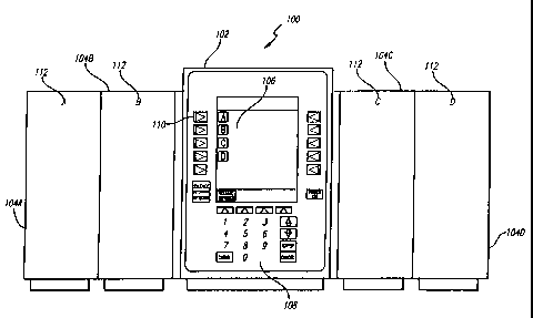
FIG. 1 discloses a modular patient care system 100 in
accordance with the present invention. Modular patient care
system 100 comprises a plurality of modules or units,
- 7 -
CA 02263315 1999-02-08
WO 98/56451 PCTIUS98/12192
including interface unit 102 and functional units 104,
detachably coupled to each other to form a linear array.
Shown in FIG. 1 are exemplary functional units 104A, 104B,
104C, and 104D coupled to interface unit 102. While four
functional units are shown in FIG. 1, a modular patient care
system in accordance with the present invention may comprise
interface unit 102 coupled to only a single functional unit
104, or may comprise interface unit 102 coupled to as many as
"N" functional units 104.
Interface unit 102 generally performs the functions of
(1) providing a physical attachment of the system to
structures such as IV poles and bedrails, (2) providing
electrical power to the system, (3) providing an interface
between the system and external devices, (4) providing a user
interface to the system, and (5) providing overall system
control, which includes providing information to and
receiving information from functional units 104. Shown in
FIG. I are certain user interface aspects of interface unit
102, which may include an information display 106, numerical
hardkeys 108, and softkeys 110.
Functional units 104 are generally for providing patient
therapies or monitoring responsive to information, at least
some of which may be received from interface unit 102. In
many cases, functional units 104 are also for communicating
information to interface unit 102. For example, functional
unit 104A may be an infusion pump unit for delivering fluids
to a patient responsive to certain commands received from
interface unit 102, while functional unit 104B may be a blood
pressure monitoring unit for providing patient blood pressure
information to the interface unit 102. The scope of the
invention is not so limited, however.
For the purposes of the present invention, the specific
function of each individual functional unit 104 is not
critical. Rather, the present invention is directed toward
(1) the mechanical and electromechanical coupling of the
functional units 104 to each other and to interface unit 102,
and (2) the inter-unit detection and communications scheme of
- 8 -
~~___----- ----r ------ _
CA 02263315 1999-02-08
WO 98/56451 PCT/US98/12192
the modular patient care system 100. Thus, for purposes of
understanding the present invention, it is important only to
recognize that functional units 104 (1) require means for
detachably coupling to each other and to interface unit 102,
and (2) require means for communicating with interface unit
102.
In a preferred embodiment of the present invention,
interface unit 102 and functional units 104 are laterally
interchangeable. By laterally interchangeable, it is meant
that the modules may be placed in any order in forming a
linear array of modules. Thus, in FIG. 1, the modular
patient care system 100 may instead have its modules ordered
left-to-right in the sequence 104C, 102, 104B, 104D, 104A
without affecting its functionality. In order to be
laterally interchangeable, the units 102 and 104 of FIG. 1
should have substantially identical interconnection features
on their respective left sides, and should have corresponding
substantially identical interconnection features on their
right sides. If the units were instead for coupling in a
vertical linear array, which is within the scope of the
present invention, the interconnection features would have
substantially identical interconnection features on their
respective top sides, and would have corresponding
substantially identical interconnection features on their
bottom sides. For clarity of explanation, however, only a
left-to-right physical arrangement is described.
To achieve the lateral interchangeability described
above, each of the units 102 and 104 should also have power,
unit detection, and communication circuitry which is
complementary. By complementary, it is meant that the units
102 and 104 generally have power, unit detection, and
communications circuit contacts on a first side and on a
second side, and that the first side contacts of one unit may
be connected to corresponding second side contacts of any
other unit, with the overall linear array of units comprising
modular patient care system 100 being fully operational. In
FIG. 1, for example, the first side of a unit is the left
- 9 -
CA 02263315 1999-02-08
WO 98/56451 PCT/US98/12192
side, and the second side of a unit is the right side.
Further to this example, and as further explained later,
functional unit 104C must be capable of receiving electrical
power from interface unit 102 to its left and transferring it
to unit 104D to its right; yet, if physically interchanged
with functional unit 104B, unit 104C must be capable of
receiving electrical power from interface unit 102 to its
right and transferring it to unit 104A to its left, and so
on.
As shown in FIG. 1, each functional unit 104 may include
a unit ID indicator 112 which identifies a logical address of
the functional unit within the linear array. The logical
address of a functional unit 104 indicates its position in
the linear array relative to other functional units 104. The
logical address of a functional unit 104, such as unit 104B,
is used by the interface unit 102 to identify and uniquely
communicate with functional unit 104B in a common
communications bus environment to be described later. In a
preferred embodiment of the invention, the logical address of
a functional unit corresponds to its sequential position in
the linear array of functional units. Thus, the system shown
in FIG. 1 may illustratively contain functional units 104A-
104D with logical addresses A, B, C, and D, ordered left to
right. In this embodiment, the left side of the leftmost
unit forms an originating end of the linear array, while the
right side of the rightmost unit forms a terminating end of
the linear array.
Also in a preferred embodiment of the invention, the
logical address of a functional unit 104 is position-
dependent, not unit-dependent. Thus, for example, in FIG. 1,
if the positions of functional units 104B and 104C were
physically interchanged in the linear array, the logical
address of unit 104B would be changed to C, and the logical
address of unit 104C would be changed to B, such that the
left-to-right order of logical addresses would remain A, B,
C, and D.
- 10 -
-T ---_ __
CA 02263315 2006-11-20
FIG. 2 illustrates mechanical and electromechanical -aspects of interface unit
102 and functional units 104 in
accordance with the present invention. For purposes of the
mechanical and electromechanical aspects of the invention,
interconnection features of interface unit 102 are similar to
interconnection features of functional units 104 and thus
only an exemplary unit 104A will be described. Also, an
exemplary unit 104B, substantially identical to unit 104A and
for connecting thereto, will be described when needed for
clarity.
FIG. 2 shows an oblique representation of exemplary
units 104A and 104B positioned before being matably
connected. As shown in FIG. 2, unit 104A comprises a chassis
200 having a left side 202, a front 204, and a right side
206. It is to be appreciated that although Fig. 2 shows
numbered components on units 104A and 104B according to their
visibility in the oblique drawing, the units 104A and 104B
contain substantially identical numbered components. Unit
104A further comprises a male connector portion 208 on right
side 206, a female connector portion 210 on left side 202, a
male elevation feature 212 formed on right side 206, a female
recess feature 214 formed in left side 202, a catch feature
216 formed near on right side 206, and a latch 218 near left
side 202. Unit 104A further comprises cover 220 tethered to
male connector portion 208 for covering the male connector
portion 208 during periods of non-use, and pocket 222 formed
in right side 206 near male connector portion 208 for
receiving cover 220 otherwise. Unit 104A further comprises
cover 224 tethered to female connector portion 210 for
covering female connector portion 210 during periods of non-
use, and pocket 226 formed in left side 202 near female
connector portion 210 for receiving cover 220 otherwise.
Male connector portion 208 of unit 104A is positioned
and formed for hingeable connection with female connector
portion 210 of unit 104B for achieving mechanical and
electrical coupling of units 104A and 104B. In a preferred
embodiment of the invention, male connector portion 208 and
- 11 -
CA 02263315 1999-02-08
WO 98/56451 PCTIUS98/12192
female connector portion 210 also form a 15-pin electrical
connector pair for electrically coupling. This electrical
connector pair is for electrically coupling electronic
components contained in units 104A and 104B.
In accordance with the present invention, functional
units 104 and interface unit 102 of FIG. 1 are provided with
hardware and software components for allowing (1) automatic
detection of attached functional units, (2) automatic
assignment of unique logical addresses of attached functional
units according to their sequential position in the linear
array of units, and (3) automatic detection of detachment of
functional units from the system. By automatic, it is meant
that associated user input is not required.
Thus, for example, in the system 100 shown in FIG. 1
which has been designed in accordance with the present
invention, system 100 is capable of automatically assigning
the logical addresses of A, B, C, and D to units 104A, 104B,
104C, and 104D, respectively, at initial power-up. Further,
if an additional unit 104E (not shown) is later added to the
right of unit 104D in the linear array while system 100 is
operating, system 100 is capable of automatically assigning
the logical address of E to the added unit 104E. If the
additional unit 104E were instead added to the left of unit
104A, system 100 is capable of assigning a logical address of
A to the added unit 104E, and capable of reassigning units
104A through 104D with the logical addresses B, C, D, and E,
respectively. Finally, if one of the operating functional
units 104 of FIG. 1 is removed inappropriately, system 100 is
capable of sounding an alarm or entering an alarm state. By
inappropriately, it is meant that interface unit 102 has not
authorized removal of the removed unit responsive to a signal
from the user or responsive to some other input, algorithm,
or condition.
Referring now to FIG. 3, interface unit 102 is shown
comprising a microprocessor 600, a transmitter 902, a first
communications bus portion 904, a receiver 906, a second
communications bus portion 908, a unit detect pullup source
- 12 -
CA 02263315 1999-02-08
WO 98/56451 PCT/US98/12192
910, a left unit detect lead 912, a right unit detect lead
914, an ID enable in lead 916, an ID enable out lead 918, and
pullup resistors 920 and 922. These elements will be
described below along with the elements of exemplary
functional unit 104A as shown in FIG. 4, which comprises a
microprocessor 700, a receiver 1002, a first communications
bus portion 1004A, a transmitter 1006, a second
communications bus portion 1008A, a unit detect bus portion
1010A, a pull-down transistor 1011, an internal pullup source
1012, and AND gate 1014, an ID enable in lead 1016, an ID
enable out lead 1018, and a pullup resistor 1020.
FIG. 5 shows a symbolic diagram of the inter-unit
communications scheme of system 100 in accordance with the
present invention. First communications bus portions 904,
1004A, 1004B, 1004C, and 1004D of units 102 and 104 form a
transmit communications bus 1004 when all units are coupled
together as shown in FIG. 1. Transmit communications bus
1004 originates at transmitter 904 of interface unit 102 and
couples to receivers 1002 in functional units 104, and serves
as a path for information to travel from interface unit 102
to functional units 104. Second communications bus portions
908, 1008A, 1008B, 1008C, and 1008D of units 102 and 104
likewise form a receive communications bus 1008. Receive
communications bus 1008 terminates at receiver 906 of unit
102 and couples to transmitters 1006 in functional units 104,
and serves as a path for information to travel from each
functional unit 104 to interface unit 102. The transmitters
and receivers are each coupled to the microprocessor
contained in their unit, as shown in FIG. S. In general, the
inter-unit communications configuration described forms a
multi-drop communications connection without collision
detection, as is well known in the art. In a preferred
embodiment of the invention, the transmitters and receivers
conform to the RS485 protocol. Also in a preferred
embodiment, communications buses 1004 and 1008 are each a
differential pair which allows rejection of common mode noise
appearing on the signal pair. Further in a preferred
- 13 -
CA 02263315 1999-02-08
WO 98/56451 PCT/US98/12192
embodiment of the invention, for single-fault mitigation, the
transceivers and receivers on the interface unit 102 and
functional units 104 are capable of switching from full-
duplex operation, wherein communication on a single bus is
unidirectional, to half-duplex operation, wherein
communication on a single bus is bidirectional.
While the communications buses 1004 and 1008 provide the
general means for high-level communications among units,
further circuitry and software to provide logical address
assignments to the functional units because the
communications buses are incapable of detecting the relative
positions of the functional units 104 and interface unit 102
in the array of units.
Means for achieving this result are described with
reference to FIGS. 3, 4, 6A and 6B. Shown in FIG. 4 is a
unit detect bus portion 1010A for coupling to the unit detect
bus portions of other functional units 104 and for coupling
to left unit detect lead 912 or right unit detect lead 914 of
interface unit 102 (FIG. 3). This coupling forms left and
right unit detect buses 1200L and 1200R, as shown in FIGS. 6A
and 6B. FIG. 3, in turn, shows unit detect pullup source 910
coupled through pullup resistors 920 and 922 to unit detect
leads 912 and 914, respectively, for pulling up buses 1200L
and 1200R, respectively (FIGS. 6A and 6B). Finally, FIG. 4
shows pulldown transistor 1011 in exemplary functional unit
104A coupled to unit detect bus portion lOlOA, and thus to
unit detect bus 1200L. As shown, transistor 1011 is capable
of pulling down unit detect bus 1200L or 1200R (FIGS. 6A and
6B), depending on which side of interface unit 102 the
functional unit 104 is on, responsive to a positive signal
from a PULLDOWN lead of microprocessor 700, to which it is
coupled. Operationally, then, any functional unit 104 is
capable of pulling down unit detect bus 1200L or 1200R
responsive to software instructions executed by its
microprocessor 700.
As shown in FIG. 3, interface unit comprises an ID
enable in lead 916 and an ID enable out lead 918. ID enable
- 14 -
. _~.~._...- __
CA 02263315 1999-02-08
WO 98/56451 PCT/US98/12192
out lead 918 is coupled to a UNIT_ID_ENABLE_R pin of a
microprocessor 600 and is capable of going high or low
according to instructions carried out within microprocessor
600. As shown in FIG. 4, exemplary functional unit 104A
comprises ID enable in lead 1016 which is coupled to a
CONNECT_SENSE pin of microprocessor 700 and to a first input
of AND gate 1014. The AND gate 1014 also has a second input
coupled to a UNIT_ID_ENABLE pin of microprocessor 700, which
is capable of setting UNIT_ID_ENABLE high or low responsive
to instructions carried out within microprocessor 700. The
AND gate 1014 has an output coupled to ID enable out lead
1018, which is high only if both the ID enable in lead 1016
is high and UNIT_ID_ENABLE are high. ID enable in lead 1016
is also coupled to internal pullup source 1012 through pullup
resistor 1020. A key feature of the present invention is
that the resulting voltage at CONNECT SENSE, and thus the
first input of AND gate 1014, is in a high state and remains
pulled up unless it is brought down by an external ground or
"low" signal placed on ID enable in lead 1016.
FIGS. 6A and 6B show the interconnections of the above
signals and leads of the units 104 and 102 when attached in a
linear array according to the present invention. As
described above, left and right unit detect buses 1200L and
1200R are formed by the respective unit detect bus portions
1010 of functional units 104 and the unit detect leads 912
and 914 of interface unit 102. Further, for any adjacent
pair of units, the ID enable in lead 1016 or 916 of the unit
on the right is coupled to the ID enable out lead 1018 or 918
of the unit on the left. Importantly, the ID enable in lead
1016 or 916 of the leftmost (or originating) unit is left
disconnected. The ID enable out lead 1018 or 918 of the
rightmost (or terminating) unit is also left disconnected.
Generally, a key to the present invention is that upon a
change in configuration, a logical address is only assigned
to a functional unit 104 if the microprocessor of that unit
detects CONNECT_SENSE to be high. CONNECT_SENSE will only be
high for (1) the leftmost unit, and (2) any unit whose ID
- 15 -
CA 02263315 1999-02-08
WO 98/56451 PCT/US98/12192
enable in lead 1016 is not pulled down by the ID enable out
lead 1018 or 916 of the unit to its left. In this way, and
in a general sense, each functional unit 104 is assigned a
sequential logical address by setting UNIT_IDENABLE to low,
waiting for CONNECT_SENSE to go high, sending a ready-for-ID
message to the interface unit 102 and receiving a logical
address from the interface unit 102 by communicating over
buses 1004 and 1008, and then setting UNIT_ID_ENABLE to high.
A description of the sequence of steps carried out by
microprocessor 600 of interface unit 102 and microprocessors
700 of functional units 104 follows. It is to be recognized
in the following disclosure that microprocessor 600 of
interface unit 102 is capable of sending commands to
microprocessors 700 of functional units 104, and receiving
responses from microprocessors 700, by means of the inter-
unit communications circuitry described previously. Also, it
is to be recognized that microprocessor 600 of interface unit
102 is capable of sensing the following signals:
UNIT_DETECT_L corresponding to the voltage on left unit
detect lead 912; UNIT_DETECT_R corresponding to the voltage
on right unit detect lead 914; MODDETL corresponding to the
voltage on left module detect lead 614; and MODDETR
corresponding to the voltage on right unit detect lead 616.
It is also to be recognized that microprocessor 600 is
capable of creating a signal UNIT_ID_ENABLE_R and driving the
voltage on ID enable out lead 918 according to this signal.
Further, it is to be recognized in the following
disclosure that microprocessor 700 of exemplary functional
module 104A is capable of receiving commands and sending
responses to microprocessor 600 of interface unit 102 by
means of the inter-unit communications circuitry described
previously. Also, it is to be recognized that microprocessor
700 is capable of sensing: the CONNECT_SENSE signal which
corresponds to the voltage at ID enable in lead 1016 and at
the first input of AND gate 1014; the signal MODDETL
corresponding to the voltage at left module detect lead 714;
and the signal MODDETR corresponding to the voltage at right
- 16 -
CA 02263315 1999-02-08
WO 98/56451 PCT/US98/12192
module detect lead 716. Also, it is to be recognized that
microprocessor 700 is capable of the following: driving the
gate of transistor 1011 to low by means of a signal PULLDOWN,
therefore pulling down unit one of unit detect buses 1200L or
1200R depending on which side of interface unit 102 the
functional unit 104A is positioned; and generating the second
input to AND gate 104 by means of a signal UNIT_ID_ENABLE.
FIG. 7 illustrates steps carried out by microprocessor
600 of interface unit 102 in accordance with the present
invention. Beginning at step 1300, step 1302 is first
performed. Step 1302 comprises steps, beyond the scope of
the present disclosure but capable of being programmed by a
person of ordinary skill in the art, wherein microprocessor
600 detects if the system 100 is in an initial power-up
state. Step 1302 further comprises steps wherein
microprocessor 600 detects whether two functional modules 104
have been simultaneously added, one to each side of the
linear array of units. This may be achieved, for example, by
detecting simultaneous low values of UNIT_DETECT_L and
UNIT_DETECT_R, which are driven low by the added units as
described later. If the system is at initial power-up or two
functional units have been simultaneously added, step 1400,
as described in FIG. 8, is performed, followed by a repeating
of step 1302 according to FIG. 7. Otherwise, step 1304 is
performed.
Step 1304 comprises the step of detecting whether a new
functional unit has been added to the left side of the linear
array of system 100. This is performed by detecting a low
value for UNIT_DETECT_L, which is driven low by the added
unit as described later. If a unit has been added to the
left, step 1500, as shown in FIGS. 9A and 9B, is performed,
followed by a repeating of step 1302 according to FIG. 7.
Otherwise, step 1306 is performed.
Step 1306 comprises the step of detecting whether a new
functional unit has been added to the right side of the
linear array of system 100. This is performed by detecting a
low value for UNIT_DETECT_R, which is driven low by the added
- 17 -
CA 02263315 1999-02-08
WO 98/56451 PCT/US98/12192
unit as described later. If a unit has been added to the
right, step 1600, as described in FIG. 19, is performed,
followed by a repeating of step 1302 according to FIG. 7.
Otherwise, step 1308 is performed.
Step 1308 comprises the step of detecting whether a
functional unit has been detached from the left or right
sides. The detachment of a unit may be detected by one or
more of three methods. First, a communications time-out with
a detached module over the inter-unit communications
circuitry may be detected. Second, a change of state of
MODDETL or MODDETL may be detected. Third, a high-level
communications signal sent by the unit adjacent to the
detached unit may be detected, in response to its own
detection of a change of state of MODDETL or MODDETR. If a
detachment of a functional unit has taken place, step 1310 is
performed. Otherwise, step 1302 is performed again in
accordance with FIG. 7.
Step 1310 generally comprises the step of determining
whether the system is currently in an operational state. If
so, the system is placed in an alarm state by step 1312,
wherein audio and/or visual alarms may be activated.
Otherwise, if the system is not in an operational state, step
1314 is performed, wherein verification by a user is
requested by means of visual and audible indications to the
user. If verification is not received, the step 1312 alarm
steps are followed.
If verification is received, step 1314 is performed,
wherein it is determined if the unit has been detached from
the left. This information may already have been determined
at step 1308. If a unit was detached from the left, step
1500, as shown in FIGS. 9A and 9B, is performed, followed by
step 1302 according to FIG. 7. Otherwise, a unit has been
detached from the right, wherein step 1318, comprising the
step of dropping the ID's of the detached unit or units, is
performed, followed by step 1302 according to FIG. 7.
FIG. 8 illustrates steps carried out by step 1400, which
first comprises the step of executing a Power-On-Self-Test
- 18 -
CA 02263315 1999-02-08
WO 98/56451 PCT/US98/12192
(POST) at step 1402. This is followed by step 1404, wherein
microprocessor 600 detects whether signals UNIT_DETECT_L and
UNIT DETECT R are both high. This will be the case, as
described below, when all functional units 104 have completed
an analogous POST of their own. Step 1404 repeats until this
until both UNIT DETECT L and UNIT DETECT R are high, wherein
step 1406 is performed. At step 1406, a global command is
issued by microprocessor 600 instructing all functional unit
microprocessors to pull down the unit detect buses 1200L or
1200R by setting their signals PULLDOWN to low. Following
step 1406, steps 1408 and 1410 are executed, wherein
UNIT ID ENABLE R is set to low, and an internal variable such
as IDVAL is set to "A".
Following step 1410, step 1412 is performed, wherein it
is determined whether UNIT DETECT L is high. If yes, step
1420 is performed. If not, steps 1414, 1416, and 1418 are
performed, wherein a global ASSIGN_UNIT_ID command is sent
over communications bus 1004, the logical address IDVAL is
assigned to the responding unit, and the value of IDVAL is
incremented. It is to be noted that at step 1416, the
responding unit is that functional unit which sends a ready-
for-ID message across the communications bus 1008. Step 1412
is again performed after step 1418. Thus, sequential logical
addresses are assigned to the left units, beginning at the
leftmost unit, until all left units have released the left
unit detect bus 1200L after receiving their logical ID, thus
letting UNIT_DETECT_L be pulled up by pullup source 910.
Step 1420 is entered after UNIT_DETECT_L is pulled up,
and comprises the step setting UNIT_ID_ENABLE_R to high to
allow units to the right to start receiving logical
addresses. Following step 1422, step 1424 is performed,
comprising the step of determining whether UNIT_DETECT_R is
high. If yes, all functional units to the right, if there
are any, have been assigned logical addresses and have
released right unit detect bus 1200R, and thus step 1430,
which comprises the step of returning to step 1302 according
to FIG. 7, is performed. If not, steps 1424, 1426, and 1428
- 19 -
CA 02263315 1999-02-08
WO 98/56451 PCT/US98/12192
are performed, which are substantially identical to steps
1414, 1416, and 1418 described above. Following these steps,
step 1422 is repeated to see if any functional units are
still pulling unit detect bus 1200R low. If so, steps 1424,
1426, and 1428 are repeated. If not, step 1430, which
comprises the step of returning to step 1302 according to
FIG. 7, is performed.
FIGS. 9A and 9B illustrate steps carried out at step
1500 and comprises the step 1502 of determining whether
UNIT_DETECT_L is high. As described previously,
UNIT_DETECT_L will be high after the unit attached to the
left has performed its POST and released unit detect bus
1200L. After UNIT_DETECT_L goes high, steps 1504, 1506, and
1508 are performed, wherein a global command is sent
instructing all functional units to pull down unit detect
buses 1200L or 1200R, wherein UNITIDENABLER is set to low,
and wherein an internal variable such as IDVAL is set to "A".
Following these steps, step 1510 is performed, wherein
it is determined whether UNIT_DETECT_L is high. If not,
assignment steps 1512, 1514, and 1516, substantially
identical to steps 1414, 1416, and 1418 above, are performed.
Subsequent to step 1516, step 1518 is performed, which
comprises the step of determining whether the unit which has
been assigned was an existing unit or is a newly attached
unit. This step is performed by simply communicating with
the assigned unit and receiving an indicator flag. If the
unit is an "old", i.e. existing, unit, step 1520 is carried
out in which existing operational data within system 100
corresponding to the old logical address of the unit are
reassigned to the new logical address. Otherwise, step 1510
is repeated.
When UNIT_DETECT_L is finally released after assignment
of logical units to the left, steps 1520 and 1522,
substantially similar in purpose and effect to steps 1420 and
1422 described above, are performed. While the value of
UNIT_DETECT_R is low, steps 1524, 1526, 1528, 1530, and 1532
are performed in a manner substantially reflexive to the
- 20 -
T
CA 02263315 1999-02-08
WO 98/56451 PCTIUS98/12192
performance of steps 1510, 1512, 1514, 1516, 1518, and 1520
described above, and according to FIGS. 9A and 9B. When
UNIT DETECT R finally goes high, step 1534, which comprises
the step of returning to step 1302 according to FIG. 7, is
performed.
FIG. 10 illustrates steps carried out in step 1600 and
comprises the step 1602 of determining whether UNIT_DETECT_R
is high. If so, all units attached to the right have
completed their POST as described above. After UNITDETECTR
is detected to be high, steps 1604 and 1606 are performed,
wherein a command instructing any unassigned units to pull
down unit detect bus 1200R is sent, and a variable IDVAL is
assigned to the value of the next logical unit beyond those
already assigned. Since step 1600 is entered only if a new
unit is attached to the right, only the new units need to be
assigned, starting the next logical unit address, and
existing units do not need to be reassigned.
Following step 1606, steps 1608, 1610, 1612, and 1614
are performed, which are substantially identical in purpose
and effect to steps 1422, 1424, 1426, and 1428 described
above and which are performed according to FIG. 10. After
UNIT DETECT R is released by all the right functional units,
the logical address assignment process is complete, and step
1616, comprising the step of returning to step 1302 of FIG.
7, is performed.
FIG. 11 illustrates steps taken by exemplary functional
unit 104A according to the present invention. Beginning at
step 1700, step 1702 is entered, wherein it is determined if
power has been newly applied to the functional unit, i.e.
whether the system 100 is at power-up or whether the
functional unit 104A has been newly attached. If not, step
1712 is performed. If so, steps 1704, 1706, 1708, and 1710
are performed, wherein the functional unit pulls down unit
detect bus 1200L or 1200R, sets UNIT ID ENABLE to low,
performs a POST, and then releases unit detect bus 1200L or
1200R. In this manner, interface unit 102 will detect,
according to the method described above with reference to
- 21 -
CA 02263315 1999-02-08
WO 98/56451 PCT/US98/12192
FIGS. 7 through 10, either the system initial power-up state
or the addition of new functional units. Step 1712 is then
performed.
Step 1712 comprises the general step of receiving a
command from interface unit 102 according to the general
operation of the present invention. Steps 1714 and 1716,
which follow step 1712, comprise the steps of combing the
incoming commands for certain commands which indicate that a
new logical unit address is to be assigned. At step 1714, it
is determined whether a global command instructing the unit
to pull down unit detect bus 1200L or 1200R has been
received. If so, an assignment procedure beginning at step
1720 is performed. If not, step 1716 is performed, wherein
it is determined whether a command instructing unassigned
units to pull down the unit detect bus 1200L or 1200R has
been received. If so, step 1718 is performed. If not, then
the incoming command is, at step 1717, either performed or
not performed, depending on a variety of factors
corresponding to aspects of the system 100 which are beyond
the scope of the present disclosure. Following step 1717,
the step 1712 of receiving another command is performed.
At step 1718, microprocessor 700 of exemplary functional
unit 104A determines whether or not it already has been
assigned a logical address. As an example, the exemplary
function unit 104A may already have an assigned address where
it exists on the right side of interface unit 102 in the
linear array of modules, and where an additional functional
unit has been added to the right of the linear array. In
this case, the interface unit 102 will be assigning logical
addresses to the added functional unit but not to the
exemplary functional unit 104A. Therefore, the exemplary
functional unit 104A will simply proceed with step 1717 as
shown in FIG. 11.
If the exemplary functional unit 104A has not been
assigned a logical address, assignment steps beginning at
step 1720 are performed. At step 1720, the unit detect bus
1200L or 1200R is pulled down by microprocessor 700 by means
- 22 -
CA 02263315 1999-02-08
WO 98/56451 PCTIUS98/12192
of signal PULLDOWN as described above. Following this step,
step 1800 is performed, followed by a repeating of the step
1702 according to FIG. 11.
FIG. 12 illustrates steps comprising step 1800 according
to the present invention. At step 1802, functional unit 104A
receives a command from interface unit 102. Steps 1804,
1806. and 1808 are then performed. As shown in FIG. 12,
steps 1804, 1806, and 1808 collectively comprise the steps of
determining whether (1) the received command is an
ASSIGN UNIT ID command, with (2) CONNECT SENSE being high,
(3) at a time when the functional unit has not yet been
assigned a logical address after pulling down unit detect bus
1200L or 1200R at step 1720. As described previously with
reference to FIGS. 6A and 6B, the CONNECT SENSE signal will
only be high if the functional unit is either the leftmost
unit, or if the unit immediately to the left of the
functional unit has already been assigned a logical ID.
Therefore, the presence of all of conditions (1)-(3) above
signifies that the functional unit 104A is the leftmost unit
which has not yet received a logical address, and furthermore
has just received an ASSIGN_UNIT_ID command from the
interface unit 102. Responsive to this condition, step 1809
is performed.
Step 1809 comprises the step of sending a ready-for-ID
message to the interface unit 102 over the communications bus
1008. Step 1809 is followed by step 1810, which comprises
the step of receiving the appropriate logical address IDVAL
from interface unit 1810. Following this step, step 1812 is
performed, which comprises the step of sending an ID_COMPLETE
message to interface unit 102, to indicate that interface
unit 102 may proceed with the next unit. Following this, the
steps 1814 and 1816 are performed, wherein the unit detect
bus 1200L or 1200R is released by the functional unit in
question, and wherein UNIT_ID_ENABLE is set to high. Step
1816 is followed by step 1818, which comprises the step of
returning to the step 1702 according to FIG. 11.
- 23 -
CA 02263315 1999-02-08
WO 98/56451 PCTIUS98/12192
If the unit in question is not the terminating (i.e.
rightmost) functional unit, the setting of UNIT_ID_ENABLE to
high causes AND gate 104 to set the ID enable out lead 1018
to high which, in turn, will cause an adjacent functional
unit to the right to detect a high state of CONNECT_SENSE.
This will thus enable the next functional unit in line to
receive the next logical address from the interface unit 102.
It is noted that by releasing the unit detect line 1200L
or 1200R, the functional unit 104A would cause the
UNIT DETECT L or UNIT DETECT R signals of interface unit 102
to be pulled up only if all functional units on a given side
have released the unit detect line 1200L or 1200R. As
described earlier, this is the desired result in order to
allow interface unit 102 to assign logical addresses in
accordance with the present invention.
Various embodiments of the invention have been
described. The descriptions are intended to be illustrative,
not limitative. Thus, it will be apparent to those skilled
in the art that modifications may be made to the invention as
described without departing from the scope of the claims set
out below.
30
- 24 -