Note: Descriptions are shown in the official language in which they were submitted.
CA 02263.,.,9 1999 - 02 - 08
WO 98/58173 PCT/IT98/00156
Pl~PESl~llY ~UlTABIE FORTHEUSEUPSlREAl\~ ROXlMllY
AND COAXI~LLYWI l~IRESE~CTTOA~BOMOIEC[11ARPUMP'
DESCRIPTION
The present invention relates to a getter pump especially suitable for the use
upstrea_, in proximity and coaxially with respect to a turbomolecular pump.
The getter pumps are static pumps, i.e. Iack m~rh~ni~ ~l moving members, and
their working is based on the ch~micorption of reactive gases such as oxygen,
hydrogen, water and carbon oxides by elem~ntc made of non-evaporable getter
materials (known in the field as NEG mqten~l.c). The main NEG m~tP.ri~lc are alloys
based on zirconium or th~nil~m
The getter pumps for generating and keeping the high vacuum in au enclosed
en~ironl~lcnl nearly always work combined with other pumps; in particular, the first
high-ples~u~e pumping stage is performed by m~ch~nic81 pumps such as rotary or
diffusion pumps, whereas getter pumps combined with chemical-ion, cryogenic or
turbomolecular pumps may be used for at~ining high vacuum.
It is especially advantageous to combine getter pumps with turbomolecular
pumps. In fact, the efficiency of turbomolecular pumps decreases upon decreasing of
the molecular weight of the gas and therefore their efficiency is low for hydrogen,
which is one of the gases mainly contributing to the residual pressure in evacuated
systems in the me~ lm vacuum range and is the main residual gas at pressures lower
than 10-9 hPa. On the other hand, the getter pumps are especially effective iu pumping
hydrogen, in particular for tempelalu.es ranging from room temperature to about 300
~C. Thus the combination of a getter pump and a turbomolecular pump, iu that
collll,~g di~elelll behaviors with respect to the gases present in the system oranyhow to remove, is an optimal solution for the problem of evacl~ting a chamber. In
particular, this combination is advantageous in case the chamber to be evacuated is a
working chamber used for high-vacuum operations, such as e.g. a chamber of a
" process machine of the semi-conductor industry.
These advantages are in principle ma~nmized when the two pumps are arranged
in series, with the getter pump being upstream with respect to the turbomolecular
pump. However, so far the t~,vo pumps have never been arranged in series, but have
always been mounted through flanges onto two di~erenl openings of the chamber tobe evacl~te~l in order to avoid the following problems and drawbacks:
CA 02263559 1999-02-08
W O 98/58173 PCTnT98100156
- the getter elprnpntc forming the pump are generally produced by compacting
NEG material powders; the getter pump is thus liable to loose particles possiblyhitting the turbomolecular pump blades and dan~q~ing them, or causing the
pump to grip by coming between its rotor and its stator;
5 - interposing a getter pump between the chamber to be evacuated and the
turbomolec~ r pump generally results in a decrease of the gas conductance to
this latter;
- when the getter pump is working, the non-evaporable getter _aterial must be
kept at temperatures of about 200-300 ~C; for this purpose it was so far heated
by irradiation from inside the pump by means of lamps or fil~m~nt resistances
wound upon a generally cera_ic support, or from outside the pump by mealls of
suitable heating members arranged on the purnp body; thus, a rise of the
turbomolecular pump temperature might also occur resulting in expansion of the
blades beyond the tolerances (being moreover very s_all) acceptable for a good
pump working. On the other hand, the increase of the distance between the
pumps or the incorporation of thermal shields therebetween in order to reduce
the effect of the rise of the turbomolecular pump temperature would result in a
unacceptable reduction ofthe gas fiow con-lnct~nce.
~ Another drawback, however less important than those indicated above, was the
20 fact that, by using the afo~e~ ioned heating systerns, thermocouples had to be
necec~qrily provided on the getter pump for ml~lring the temperature of the active
materiaL whereby complex tightness problems related to the wires having to come out
from a vacuum-environment had to be solved.
It is an object of the present invention to overcome the aforemeDtioned
25 drawbacks by means of a getter pump arranged upstream, in proximity and coaxially
with respect to a turbomolecular pump, in a structure connecting the chamber to be
evacl~te~l and the lu~bol~olecular pump, such as to reduce the loss of particles,
...; .;...;~.e the coll(lnct~nce reduGti~n and ~ .e the indirect rise of temperature of
the turbomolecular pump, thereby ~n~lnng an improved pumping efficiency of the
30 assembly.
Furthermore, the temperature of the getter pump may be measured according to
the invention through direct res;c~ ~~e mea~u~GI...,nls from the outside of the pum~
without having to use therrnocouples or wires passing through the pump body, with
higb reproducibility pl-opGIlies.
These and other objects, advantages and features of the getter pump according
to the present invention, as defined in claim 1, will be more evident from the following
CA 02263559 1999-02-08
WO 98/S8173 PCTIIT98/00156
- 3 -
~let~iled description of a prertlled embodiment thereof, reported by way of non-limiting examples with reference to the attached drawings, wherein:
Fi~ure la shows a secti-n~l view of the steel housing or stub, intended to have
inserted therein the getter pump according to the invention, which in
S Fi~urelb is repres~nte~1, also in sectional view, in proximity of the
structure of Fig. la;
Fi~ure 2 shows a secti~ nql view ofthe assembled getter pump, corresponding to the
assembly of Figures la and Ib;
Fi~ure 3 shows a left side view of the assembly of Figure 2; and
10 Fi~ure 4 shows a right side view of the same assembly.
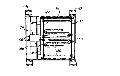
With reference to the drawings, the getter pump according to the invention is
formed of a sub~qntiqlly cylindrical cartridge 10 having two metal rings 12 12a
mutually parallel and arranged on the opposite ends of said cylinder, coaxial witll
respect to the pump and extemal with respect to its body, fastened to the innel wall of
15 cartridge 10. Rings 12 have fastened thereto the opposite ends of the real getter
device, formed of an elongated metal element coated with getter rnateriaL preferably
zigzag- or coil- shaped, with bends 18 or turning zones corresponding to f~xing and
thermal inclllqtion points 16 and 16a on rings 12 and 12a. Thus getter device 20 lies in
a marginal area of cartridge 10 which has a subst~nti~lly at~ ls configuration,
20 wherein all the getter cl ...~ c are arranged in proximity of the inner waD of cartlidge
10, in order to ..~ e the reduction of conductance or passage area of the gas flow
therethrough. It should be noted that, instead of a one-piece elemPnt zigzag Ol coil
shaped, getter device 20 rnay be formed of a set of getter el~mPnt.c successively joined
together at fixing points 16, 16a to rings 12, 12a. In both cases, the one-piece25 continuous getter element 20 or the di~elent el~mPntc joined together in series to
provide for the getter device are formed of a thread-hke mP.t~llic core, preferably but
not necessarily shaped as a coil spring having its axis coinciding with the trend
resulting from the drawings. The getter material rnay be coated on said thread-like
metallic core by inserting this latter inside a suitable mold, pouring into the mold
30 powders of the desired getter material and ~;nte~ing the powders inside the mold, e.g.
by putting it into an oven. Many di~trent getter materials may be used, generally
CO~li~g thqnillm and ~i~conium; their alloys with one or more ekPmPntc selected
among the transition metals and al.~...; .;~...; and mixtures of one or more of these
alloys and th~nillm and/or zirconium; the use of 1;~ ;.. and ~ -v~n~ lil~m alloys
35 is prer~ ed. These mqtPriqlc are to be prertt.ed owing to the powders being easily
sintered and because getter elemPntc produced by using these materials have good
CA 02263559 1999-02-08
w o 98/~8173 PCT~T98/00156
mtqfh~nirql properties and practically no loss of particles, while mqint~ining porous
properties such as to ensure excellent sorption capacity.
Anyhow, both with getter device 20 formed of a one-piece continuous element
having U-turns and with a plurality of di~erent elem~nts arranged in series, e.g. in a
zigzag arrangement, getter device 20 has two ends 22 mllhlally contiguous and lying
on the same side of cartridge 10, wherein the conlilluiLy of element 20 is interrupted.
Ends 22 protrude mutually parallel from a side of cartridge 10, so as to be inserted in a
supply box 24 in housing 30 or cf)nnecting "stub" between the chamber to be
evacusted and the turbomolecular pump (not shown), which will be hereinafter
described with reference to Figure la. Said connecting stub 30is formed of a cylinder
made of stainless steel having a diameter slightly larger than the outer diameter of
cartridge 10 and provided at its ends with two flanges 32 and 34 having through-holes~
provided for f~ ning members such as screws and bolts. Box 24 is arranged such as
far from flange 32, through which cartridge 10 is inserted, as to have, once the1~ assembhng is carried out, ends 22 inserted therein like plugs in a socket. On the
opposite side, close to flange 34, box 24 has a pair of terminals 26, directed out~ards~
having external supply c-n~luctors 28 connected thereto, as it is better seen in Figure
4.
The getter pump according to the present invention, especially suitable for the
use upstream and in proximity of turbomolecular pumps, is provided both with
upstream and downstream valves (not shown), allowing to isolate said pump from the
chamber to be eva,r,~l~te~l from the turbomolecular pump or from both of the~ assometimes l~ececC~ry for moving, replacing or m~int~ining the getter pump.
For exam~le, both the valves upstream and downstream of the getter pump are
closed while moving the pump or mounting it in working position. lt could be useful
to have the upstream valve (towards the chamber to be evacuated) open and the valve
towards the turbomolecular pump closed iu case of mqint~n~nce operations on thislatter or when in specific process steps it is enough to use the getter pump, although
the system usually also requires the turbomolecular pump.
On the contrary, isolating the getter pump from the working chamber with the
valve towards the turbomolecular pump open may be useful for the regeneration of the
getter pump. In fact, this latter is especially useful for the hydrogen sorption, which is
an equilibrium phenomenon; the hydrogen amount sorbed by a getter material
increases upon decreasing of the temperature and upon increasing of the hydrogel~
partial pres~u~e in the surrounding syste~ Thus, by increasing the temperature of a
getter which has sorbed a large hydrogen ~m~ nt7 and by working in pumping
CA 02263559 1999-02-08
WO 98/58173 PCT/IT98tO0156
conditions, e.g. in this case by using a turbomolecular pump, it is possible to discharge
the gas from the getter, thereby regenerating it.
However, the turbomolecular pumps may be damaged by an overheating when
working at a too high gas pressure, which may occur during the getter pump
5 regeneration. In order to prevent such a drawback, it is possible to slowly heat the
getter element (or e1ement~), such that also the hydrogen pressure slowly increases and
that, con~;~ler-n~ the pumping rate of the turbomolecular pump, this does not reach
critical pressures. Instead of this, the conductance between the getter pump aud the
turbomolecular pump may be red~1ced by operating on the valve arranged
1 0 therebetween.
It should be noted that, as aforelllc.-tioned, the loss of particles from the getter
materia~ coated on Pl~m~Mt 20 is very smalL owing to the product having been sintered
in a high-temperature oven. Therefore, un~ike the getter pumps of the prior alt~ the
getter pump and the turbomolecular pump may be arranged in series.
Furthermore, as for the indirect measure of the temperature through the direct
resistance mea~u~e~nl of the inner fil~ment of element 20, it should be noted that,
since the inner fil~men~ supporting the getter material and the getter powder coated
thereon are produced by controlled processes having a high reproducibility, a suitable
curve R-T is obtained having an especially good tolerance. It is therefore possible to
20 do without thermocouples in order to obtain the temperature values of the getter
device.
Finally, siuce the getter pump is heated by direct passage of current in series, the
heat absorption by the turbomolecular pump is very srnall in that it is only due to
irradiation by the getter el~m~nts in a vacuum-environment, being much smaller than
25 the irradiation by a lamp.