Note: Descriptions are shown in the official language in which they were submitted.
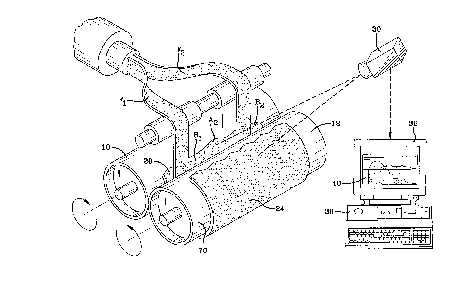
?101520253035CA 02264095 1999-02-08W0 98l09789 PCT/US96/14260SYSTEM AND METHOD FOR CONTROLLING THE SIZEOF MATERIAL BANKS IN CALENDERS, MILLS,AND FEED! MILLSTechnical FieldThis invention pertains to the art of methods and apparatuses for measuring the quantityof material in a calender bank, and more specifically to methods and apparatuses for usingdigital imaging technology in a system for measuring and controlling the size and shape of arolling calender bank. While the invention will be described in terms of processing anelastomeric material, the invention is also applicable to other materials such as pizza dough,plastics, paper pulp, or any material in which a batik is formed on a mill, calender or similarmachine.Background ArtThe size and shape of the rolling bank on a calender or mill is an important componentin the calendering process. The bank provides a buffer to keep a uniform supply of materialto the calender rolls. However, if the bank is not maintained at proper level, nonuniformitiescan appear in the calendered sheet. For example, if the bank is too low, voids can be formedin the sheet due to the "starved" condition of the bank. On the other hand, if the bank is toolarge, problems such as material scorching can occur, which produces cured or otherwiseundesirable lumps in the sheet of material. In addition, variation in rolling bank size causesvariation in the spreading force on the rolls resulting in uneven gauge of the sheet.The ability to accurately control the size of the calender bank provides more uniformresults in the calendered sheet in terms of component dimensions and composition. Inherent inthe problem of controlling the bank size is the problem of being able to accurately measure thequantity and distribution of material present in the bank.In the art, there have been a variety of methods and apparatuses employed in attemptsto solve the problems associated with determining the bank size. For example, a methoddisclosed in U.S. Patent No. 4,642,686 to Nagono et al. utilizes a video camera, a screen, anda light source to obtain a silhouette of the banked material. The area of the silhouette is thenrelated to a quantity of material. The method involves a backlighting arrangement which ismore complex than the inventive method.Japanese Document No. 59-132314 to Yonezawa et al. discloses a method by which atelevision camera records a picture of a pair of blank rolls and then records a picture of the rollshaving a bank of rubber therebetween. The difference between the pictures is obtained by asubtractor. The picture elements are then converted to black and white binary signals wherein?1015202530CA 02264095 1999-02-08WO 98/09789 PCTIUS96/142602the rubber is indicated in black. A correction means converts black portions which are belowa predetermined width to white. This direct method of obtaining binary signals does notcompensate for the problem of glare commonly encountered when shiny calendering rolls areemployed. 'European patent application 0 645 230 A1 to Hatanaka is also directed to a device foradjusting the quantity of a bank of material on a mill.The present invention provides new and improved means for measuring and controllingthe quantity of elastomeric material formed in a bank between two calendering rolls in a waywhich simply and effectively overcomes the problems currently encountered in the art.Disclosure of InventionIn accordance with the practice of the present invention, there is provided a method formeasuring the quantity of elastomeric material formed in a bank between two calendering rolls.More particularly, in accordance with the present invention, a method utilizing digitalimages obtained by camera means trained on the calendering rolls is provided.In accordance with one aspect of the invention, the method utilizes initial and secondarydigital images comprising pixels having numerical values relating to lighter and darker hues.The initial image is obtained when the elastomeric material is absent and the secondary imageis obtained when said elastomeric material is present. The inventive method is characterizedby the steps of:combining the initial and secondary images to form a third digital image whereinthe elastomeric material is indicated by lighter hues;excluding a portion of the third image which corresponds to the presence of theelastomeric material on a surface of the second roll;measuring an area of lighter hues; and,relating the area to the quantity of elastomeric material in the bank.In accordance with another aspect of the invention, the third digital image is optionallymultiplied by an integer constant to increase a contrast between lighter and darker hues.In accordance with another aspect of the invention, the numerical values of each of thepixels of the third digital image are compared to a predetermined standard, and values abovethe standard are converted to pure white hues, and values below the standard are converted topure black hues.In accordance with another aspect of the invention,the third digital image is corrected for perspective and lens distortion.?1015202530CA 02264095 1999-02-08WO 98/09789 PCT/US96/142603In accordance with another aspect of the invention, the number of pixels correspondingto the lighter hues are compared with a total number of pixels in the third digital image toobtain a fraction of the image corresponding to the elastomeric material. A calibration matrixis then utilized to convert the fraction to an actual cross-sectional area of elastomeric materialpresent in the bank.In accordance with another aspect of the :invention, a method for controlling the quantityof elastomeric material contained in a bank between calendering rolls in a calendering apparatusis provided. The method utilizes initial and secondary digital images comprising pixels havingnumerical values relating to lighter and darker hues. The initial image is obtained when theelastomeric material is absent and the secondary image is obtained when the elastomeric materialis present. The inventive method is characterized by the steps of:combining the initial and seconda:ry images to form a third digital image whereinthe elastomeric material is indicated by lighter hues;excluding a portion of the third image which corresponds to the presence of theelastomeric material on a surface of the second roll;measuring an area of lighter hues;relating the area to a total quantity of the elastomeric material in the bank;comparing the total quantity of the elastomeric material in the bank with apredetermined optimal quantity; and,adjusting a feed rate of the elastomeric material to the calendering apparatus.In accordance with another aspect of the invention, the elastomeric material is fed to thebank through a plurality of feed lines. In add:ition, the third digital image is divided into aplurality of zones, each zone corresponding to a region of the bank being fed by one of the feedlines. The quantity of elastomeric material contained in each of the regions is determined andcompared to the total quantity of elastomeric material in the bank. The quantity of elastomericmaterial in each region is further be compared to the optimal quantity of elastomeric materialin the bank.In accordance with another aspect of the invention, the distribution of elastomericmaterial through each feed line is altered to optimize the quantity of elastomeric material in eachregion of the bank.In accordance with another aspect of the invention, a system for determining the quantityof elastomeric material contained in a bank between first and second closely juxtaposedcalendering rolls in a calendering apparatus is provided. The system utilizes initial and?1015202530CA 02264095 1999-02-08W0 98l09789 PCTIUS96/142604secondary digital images obtained by camera means trained on said rolls. The inventive systemis characterized by:combining means for combining the initial and secondary images to form a thirddigital image wherein the elastomeric material is indicated by lighter hues;excluding means for excluding a portion of the third image which correspondsto the presence of the elastomeric material on a surface of the second roll;measuring means for measuring an area of lighter hues; andconverting means for converting the area to the quantity of elastomeric materialin the bank.In accordance with another aspect of the invention, the system includes contrasting meansfor increasing the contrast between the lighter and darker hues of the third image.In accordance with another aspect of the invention, the system further includes correctionmeans for correcting the third digital image for perspective and lens distortion.One advantage of the present invention is overcoming the problem of imaging of shiny,highly re?ective calender rolls.Another advantage of the present invention is being able to exclude any elastomericmaterial covering a portion of the second roll.Another advantage of the present invention is the ability to control the amount ofelastomeric material contained in each region of the bank.Still other benefits and advantages of the invention will become apparent to those skilledin the art to which it pertains upon a reading and understanding of the following detailedspecification.Brief Description of DrawingsThe invention may take physical form in certain parts and arrangement of parts, apreferred embodiment of which will be described in detail in this specification and illustratedin the accompanying drawings which form a part hereof and wherein:Figure 1 is a perspective view of camera means trained on a bank of elastomeric materialbetween a pair of calendering rolls; and,Figure 2 is a schematic representation of a system for measuring and controlling thequantity of elastomeric material in a bank according to the present invention.Detailed Description of the InventionReferring now to the drawings wherein the showings are for purposes of illustrating apreferred embodiment of the invention only and not for purposes of limiting the same, Figure?1015202530CA 02264095 1999-02-08WO 98/09789 PCT/US96/1426051 shows first and second calendering rolls 10, 12 respectively and a bank 20 of elastomericmaterial 24 contained therebetween. While the preferred embodiment of the present inventionwill be described with particular reference to a pair of calendering rolls in a calenderingapparatus, the invention is equally applicable to mills and feed mills to hot feed extruders (notshown). Further, while the invention will be described with reference to elastomeric materialsand with reference to the rubber processing industry and with reference to specifically tirecomponents made of such processed rubber, the invention has wider applicability. For example,any material which is processed on a mill by creating and maintaining a bank is a candidate forthe invention. For example, in the food industry where dough, such as pizza dough, isprocessed in large quantities on mills, the problems inherent in maintaining bank size are alsosolvable by the invention. Throughout this application, the invention is described withreference to elastomeric material which is nearly always darker than the rolls. However, somematerials, such as pizza dough, will actually have a hue which is lighter than the hue of therolls. The important issue is that the hue of the material be contrasted (lighter or darker) thanthe hue of the rolls after the combining means.Camera means 30 trained on rolls 10, 12 obtains images of the rolls 10, 12 and anyelastomeric material 24 present. The images may be observed on monitoring means 36 andstored in computing means, such as a computer 38. Digital imaging technology allows imagemanipulation functions on the digital images 4-0 to elicit data concerning the quantity anddistribution of elastomeric material 24.With reference to Figures 1 and 2, a system 50 for determining the quantity ofelastomeric material 24 contained in a bank 20 between calendering rolls 10, 12 will bedescribed. Figure 2 also includes typical outputs which may be observed on monitoring means36 as digital imaging technology is employed to manipulate the images 40 collected by camerameans 30.The system 50 for detennining the quantity of elastomeric material 24 contained in abank begins by initializing the computer 38 and camera means 30 in preparation for imagecollection and manipulation. An initial image 54 of the bare calender rolls 10, 12 is acquiredby camera means 30 and stored in storing means 58 for use as a baseline reference to which allsubsequent images are compared.A secondary image 60 is obtained when elastomeric material 24 is present. The camerameans 30 is positioned so that the secondary image 60 includes a profile 64 of the bank 20against first calender roll 10. The secondary image 60 may also includes a pro?le 68 of?1015202530CA 02264095 1999-02-08WO 98/09789 PCT/US96Il42606elastomeric material 24 which is contained on a surface 70 of second roll 12 which commonlyoccurs in a calendaring operation. The secondary image 60 is then stored in the storing means58 for future operations.The system 50 employs combining means 74 for digitally combining the initial andsecondary images 54, 60. The output from the combining means 74 yields a third digital image80 wherein the elastomeric material 24 is indicated by lighter hues and the background andcalender rolls 10, 12 are indicated by in darker hues. An important aspect of the invention isthe "negative" of the elastomeric material 24 contained in the third digital image 80. The initialand secondary images 54, 60 are combined (subtracted) in such a way as to eliminate theproblems often encountered in the art associated with the glare produced by shiny highlyre?ective calender rolls.The inventive system can optionally further employ contrasting means 84 whereby thelighter hues are effectively brightened to provide a greater contrast between lighter and darkerhues. The preferred contrasting means 84 multiplies the numerical value of each pixel of thethird digital image 80 by an integer factor.One embodiment of the inventive system 50 includes comparing means 88 for comparingthe numerical values of each pixel of the third digital image 80 to a predetermined standard andconverting values above the standard to pure white hues and converting values below thestandard to pure black hues. Therefore an image 94 having only pure white and pure black huesis obtained.The system 50 further includes excluding means 100 whereby the profile 68 of theelastomeric material 24 on the second calender roll 12 is excluded. Only the profile 64 of thebank 20 remains as lighter hues in an image 102.One embodiment of the inventive system 50 includes correction means 106 for correctingthe profile 64 in image 102 for lens and perspective distortions. The image correction isperformed from the middle of the image 102 outward in both horizontal and vertical directions.Measuring means 110 are employed to obtain a cross-sectional area, A,, of the profile64 of the bank 20 in terms of the number of white pixels in the image 102.Converting means 114 can then convert the measured area A1 into a real cross-sectionalarea A2 of the bank 20 by use of a calibration matrix. Real cross-sectional area A2 can then berelated to the quantity of elastomeric material 24 in the bank 20. One means for relating thereal cross-sectional area A2 to quantity of elastomeric material 24 in bank 20 utilizes volumeof revolution methods.?1015202530CA 02264095 1999-02-08W0 98l09789 PCT/US96/142607A preferred embodiment of the inventive system 50 further includes dividing means 120for dividing the profile 64 of bank 20 into control zones Zn corresponding to discrete regionsB,, of the bank 20 being fed by separate feed lines F,,. For the sake of simplicity, two controlzones Zl, Z2 are shown in Figure 2 which correspond to regions B1, B, respectively, which arefed by feed lines F1, F2, respectively, as shown in Figure 1. It is readily apparent, however,that finer control of the quantity of elastomeric material 24 in bank 20 may be obtained throughthe use of a greater number of control zones Zn.The quantity of elastomeric material 24 contained in the bank 20, or in each discreteregion B", can then be controlled by adjusting the overall rate at which elastomeric material 24is fed to the calendering apparatus or by controlling the rate at which elastomeric material 24is fed through each discrete feed line F,,.A method for measuring and controlling the quantity of elastomeric material 24 containedin a bank 20 between first and second calendering rolls 10, 12 will be described with referenceto Figures 1 and 2. Camera means 30 trained on first and second closely juxtaposedcalendering rolls 10, 12 records an initial digital image 54 of the rolls 10, 12. Elastomericmaterial 24 is fed to the calendering rolls 10, 12â. and a secondary digital image 60 is taken ofthe rolls 10, 12 including elastomeric material 24 contained in a bank 20 therebetween. Thedigital images 54, 60 comprise pixels (picture elements) having numerical values relating tolighter and darker hues. In the inventive method, the initial image 54 and secondary image 60are combined to form a third digital image 80 wherein the elastomeric material is indicated bylighter hues. In the combining step, the calendering rolls 10, 12 are included in the backgroundand indicated by darker hues. The profile 68 of the elastomeric material 24 on the surface 70of the second roll 12 is excluded from the third image 80 by converting it to darker hues. Thearea A, of profile 64 of bank 20 indicated by lighter hues can then be measured in terms of thenumber of pixels and converted to a real cross-sectional area A2 of elastomeric material 24 inthe bank 20. The cross-sectional area A2 of the elastomeric material 24 in the bank 20 is thenrelated to the quantity of elastomeric material 24. In a preferred method, the number of pixelscorresponding to lighter hues is compared with a total number of pixels in the third digitalimage 80 to obtain a fraction of the image 80 corresponding to the elastomeric material 24. Acalibration matrix converts the fraction into an actual cross-sectional area A2.In a preferred method, the contrast between lighter and darker hues in the third digitalimage 80 can be increased by multiplying the third digital image 80 by an integer constant.?101520CA 02264095 1999-02-08W0 98/09789 PCT/US96/ 142608Also, in a preferred method, the numerical values of each pixel of the third digital image80 is compared to a predetermined standard. Values above the standard (lighter hues) areconverted to pure white while values below the standard (darker hues) are converted to pureblack. In this way, the contrast between lighter hues and darker hues is maximized and thebackground is eliminated from later manipulations.In a preferred method, corrections for perspective and lens distortion are made toprovide accurate information about the elastomeric material 24 in the bank 20.A preferred method for determining the quantity of elastomeric material 24 in a bank 20further comprises dividing the profile 64 of bank 20 into a plurality of control zones Zn.In a preferred method of controlling the quantity of elastomeric material 24 in the bank20, each of the control zones Z,, are associated with a discrete region B,, of the bank 20 whichis fed by a separate feed line Fâ. The information regarding the area of each control zone Zâis related to quantity of elastomeric material 24 in each region B,, and can be adjusted to obtainoptimum feed rates and distribution.The preferred embodiments have been described, hereinabove. It will be apparent tothose skilled in the art that the above methods may incorporate changes and modificationswithout departing from the general scope of this invention. It is intended to include all suchmodifications and alterations in so far as they come within the scope of the appended claims orthe equivalents thereof.Having thus described the invention, it is now claimed: