Note: Descriptions are shown in the official language in which they were submitted.
CA 02264368 1999-03-03
A MULTI-TERRAIN VERTICAL LIFT TRANSPORTER
FIELD
This invention relates to a self-propelled multi-terrain
vertical lift transporter for lifting and transporting loads
over various soil conditions and terrain.
BACKGROUND OF THE INVENTION
1o Forklift trucks are widely used in a variety of
applications and come in many different shapes and sizes. In
particular, many forklifts have been designed especially for
light duty applications. However, these light duty forklifts
typically have a fixed wheel base making it difficult to use
z5 them in narrow passageways and at the same time lack the
requisite stability to avoid tipping or overturning in
response to unbalanced loads or encountering variable
terrain.
2o U.S. Patent No. 4,571,139 issued February 18, 1986 to
Moseley et al. discloses a freight handling truck comprising
a frame mounted on at least three wheels, a supporting mast,
lifting forks and a motor. Of the three wheels, at least one
is a driving wheel powered by the motor and the other two
25 wheels are idler wheels, mounted on two horizontally pivotal
wheel arms . The pivotal wheel arms are powered by the motor
to pivot them laterally to either widen or narrow their
1
CA 02264368 1999-03-03
lateral extent. The pivotal wheel arms are also telescopic,
allowing them to extend or retract. In the freight handling
truck disclosed by Moseley et al. the wheels mounted at the
ends of the adjustable wheel arms are not capable of pivoting
or re-orienting as the wheel arms pivot. Therefore, the
wheels mounted on the adjustable wheel arms are parallel with
the path of travel of the device for only one angle of the
wheel arms. Thus increased friction occurs when the angle of
the wheel arms is changed to different angles. Also, the
to freight handling truck, as disclosed by Moseley et al.,
cannot lower a load to the floor if the pivotal wheel arms
are in the narrowed position. The freight handling truck
disclosed by Moseley et al. is further limited in that it is
incapable of performing a tight radius turn.
It is, therefore, an object of this invention to provide
a lift transporter with improved stability and
maneuverability.
2o It is a further object of this invention to provided a
lift transporter which is capable of laterally adjusting its
wheel base.
It is a further object of this invention to provide a
lift transporter capable of performing a tight radius turn.
2
CA 02264368 1999-03-03
It is a further object of this invention to provide a
lift transporter which is reduced in weight.
SUMMARY OF THE INVENTION
The lift transporter of this invention is constructed of
a steel frame which houses a motor and the hydraulic systems.
1o Four wheels, two front and two rear, are mounted onto the
frame. The two front wheels are mounted on laterally
adjustable outriggers which are arranged outside of the
lifting forks. The separation of the laterally adjustable
outriggers, through the operation of the hydraulic systems,
i5 can be widened or narrowed as required. The two rear wheels
are mounted on a common axle which is journaled to a post.
Thus, the rear wheels are locked together for improved
traction and are hydraulically powered. The front and rear
wheels are of a sufficient width and tread design to allow
2o the lift transporter to move over various terrain including
gravel, sand and mud.
The lift platform of the lift transporter may consist of
lifting forks, or other lifting implements, all of which can
25 be interchanged simply by lifting one implement off of the
horizontal members of the lift carriage and replacing it with
3
CA 02264368 1999-03-03
another implement. The lift carriage is hydraulically
powered to be raised and lowered.
The lift transporter is steered utilizing a tiller
handle. Mounted to the neck of the tiller handle are the
controls for raising and lowering the lift assembly, moving
the lift transporter forward and reverse, and widening and
narrowing the laterally adjustable outriggers. Also, the
tiller handle and the rear wheel assembly are constructed to
1o pivot through a wide range thereby allowing the lift
transporter to perform tight radius turns.
The improved lift transporter of this invention does not
require a counter weight as the center of gravity of any load
is substantially within the wheels and thus cannot tip the
unit.
Other objects and advantages of the invention will
become clear from the following detailed description of the
2o preferred embodiment, which is presented by way of
illustration only and without limiting the scope of the
invention to the details thereof.
4
CA 02264368 1999-03-03
BRIEF DESCRIPTION OF THE DRAWINGS
The invention itself both as to organization and method
of operation, as well as additional objects and advantages
thereof, will become readily apparent from the following
detailed description when read in connection with the
accompanying drawings, wherein:
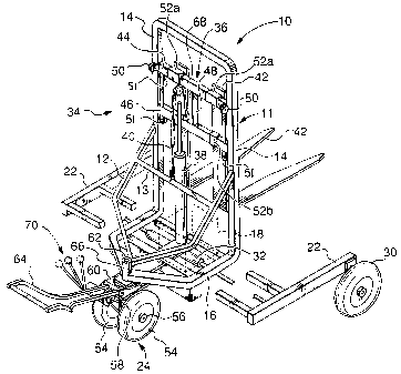
Fig. 1 is a perspective view of the lift transporter
1o with lifting forks as the lift platform;
Fig. 2 is a front view of the lift transporter with the
outriggers in a narrowed position;
Fig. 3 is a front view of the lift transporter with the
outriggers in a widened position; and
Fig. 4 is a rear view of the lift transporter with the
outriggers in a narrowed position and the tiller handle has
been removed for clarity.
DETAILED DESCRIPTION OF THE INVENTION
Throughout the figures, like elements are indicated by
like reference numbers. Referring to Figs 1 to 4, the lift
transporter 10 includes a frame 11 which houses a motor 18
5
CA 02264368 1999-03-03
and the hydraulic systems (not shown). Frame 11 is comprised
of vertical support portions 12, horizontal support portion
13, mast portions 14 and base portion 16. Slidably mounted
to the underside of base portion 16 of frame 11 are laterally
adjustable outriggers 22. The rear wheel assembly 24 is
pivotally mounted to the rear of base portion 16 of frame 11.
The rear wheel assembly 24 comprises rear wheels 54,
wheel axle 56, wheel post 58, tiller plate 60, tiller post
62 and tiller handle 64. The rear wheels 54 are mounted on
a common wheel axle 56 which is operatively coupled to the
wheel post 58. The wheel post 58 is mounted to the lower
surface of the tiller plate 60. The tiller post 62 is
mounted on the upper surface of tiller plate 60. The tiller
post 62 is received in post receptacle 66 located at the rear
junction of the base portions 16 of the frame 11. The tiller
post 62 is pivotally secured in the post receptacle 66 to
allow the rear wheel assembly 24 to rotate about tiller post
62. The tiller handle 64 is mounted on the upper surface of
2o tiller plate 60 such that the rear wheels 54 and the tiller
handle 64 are parallel. The control levers 70 are mounted on
the neck of the tiller handle 64. The control levers 70
operate to actuate the various cylinders that are used in the
operation of the lift transporter 10. The rear wheels 54 are
operatively coupled to motor 18 by any suitable power
transmission means.
6
CA 02264368 2003-02-25
Mounted at the distal ends of the laterally adjustable
outriggers 22 are the idler wheels 30. The idler wheels 30
are preferably mounted on a fixed axis and so do not turn
to either side. The laterally adjustable outriggers 22 are
operatively coupled to the hydraulic cylinder 32.
Hydraulic cylinder 32 operates to widen and narrow the
laterally adjustable outriggers 22.
The lift assembly 34 comprises the lift carriage 36,
hydraulic cylinder 38, chain 40, rotatable sprocket 68 and
lift implement 42. The lift carriage 36 is I-shaped with
upper horizontal member 44, lower horizontal member 46 and
vertical member 48 being mounted between the upper and
lower horizontal members 44 and 46. The lift carriage 36
is slidably mounted to mast portions 14 of frame 11.
Mounted on the ends of upper horizontal member 44 are front
guide rollers 50, and mounted on the ends of lower
horizontal member are rear guide rollers 53 which engage
mast portions 14. Rollers 51 are mounted inside each end
of the upper and lower horizontal members 44 and 46, and
protrude slightly to roll over the inside of the mast
portions 14. A rotatable sprocket 68 is mounted to the top
of hydraulic cylinder 38 with a chain 40 engaging the
rotatable sprocket 68. One end of chain 40 is secured to
the vertical member 48 of the lift carriage 36, and the
other end of chain 40 is secured to the horizontal support
7
CA 02264368 2003-02-25
portion 13 of frame 11. Thus, the lift carriage 36 is
raised and lowered through the operation of hydraulic
cylinder 38.
The lift implement 42 is detachably secured to the
horizontal members 44 and 46 of the lift carriage 36 by
upper and lower hook braces 52a and 52b. The lift
implement 42 may take on a variety of forms, including, but
not limited to forks, a bucket and a large planar surface.
A lift implement of one form may be substituted for a lift
implement of another form by lifting hook braces 52a and
52b of lift implement 42 from horizontal members 44 and 46,
respectively, and placing the hook braces of an alternate
lift implement onto horizontal members 44 and 46.
The motor 18 is sufficiently powerful to drive either
the rear wheels 54 while under a load of about 5001bs, the
hydraulic systems (not shown) to operate the laterally
adjustable outriggers 22 to widen or narrow them when the
lift transporter 10 is under a load of about 5001bs, or the
hydraulic systems to allow the lift transporter 10 to raise
a load of about 5001bs.
In operation, a user steers the lift transporter 10
through tiller handle 64. Tiller handle 64 can be pivoted
in the horizontal plane parallel to the ground through a
8
CA 02264368 2003-02-25
range of about 220q. A user utilizes control levers 70 to
actuate the various hydraulic cylinders necessary to
operate the lift transporter 10. Hydraulic cylinder 38 is
actuated to raise and lower the lift carriage 36 and
hydraulic cylinder 32 is actuated to widen and narrow the
laterally adjustable outriggers 22. The control levers 70
also regulate the speed and direction of the lift
transporter 10 when engaging the power transmission means
of the rear wheels 54. The control levers 70 are designed
such that only one of the rear wheel assembly 24, the
laterally adjustable outriggers 22 or the lift assembly 34,
may be in operation at one time.
To lift a load, the lift transporter 10 is directed
using tiller handle 64. The rear wheels 54 are engaged,
through the control levers 70, to propel the lift
transporter 10 to the target location. At any point, the
rear wheels 54 may be disengaged and the laterally
adjustable outriggers 22 may be widened or narrowed. The
laterally adjustable outriggers 22 may be narrowed to
accommodate a narrow load or pass through a narrow space,
or the laterally adjustable outriggers 22 may be widened to
accommodate a wider load. The adjustment of the laterally
adjustable outriggers is effected through the actuation of
hydraulic cylinder 32 through the control levers 70. Once
the lift implement 42 has been positioned under the load,
9
CA 02264368 2003-02-25
the user utilizes control levers 70 to raise the load.
Hydraulic cylinder 38 is actuated to extend its piston,
thereby raising the lift carriage 36 to which the lift
implement 42 is detachably secured. V~hen the load has been
raised to the appropriate height, the laterally adjustable
outriggers 22 may be adjusted once again. The load on the
lift implement 42 is within the wheel base of the lift
transporter 10, preventing tipping of the lift transporter
by an imbalance in the load.
It will be appreciated by those skilled in the art
that the lift transporter of this invention is
distinguished by its versatility, simplicity, and
efficiency. Moreover, the design of the lift transporter
precludes the need for a counter-weight thereby decreasing
the weight of the lift transporter making it easier to
maneuver and control.
Furthermore, it will be understood that the motor,
hydraulic cylinders, hydraulic systems, etc. used
throughout this invention may be of any desired design
according to the knowledge of those skilled in the art and
operate in conventional fashion to achieve the intended
result. Indeed, the hydraulic cylinders, may be replaced
with electric or pneumatic equipment, if so desired.
CA 02264368 2003-02-25
Although the present invention has been described in
detail with reference to one preferred embodiment, it will
be clearly understood that this is by way of illustration
only. Many variations and alternative embodiments of the
invention will now be apparent to those skilled in the art,
and are not to be excluded from the scope of the invention,
which is to be determined only by the appended claims, as
set forth below.
11