Note: Descriptions are shown in the official language in which they were submitted.
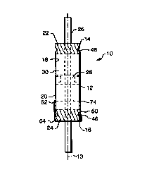
101520253035WO 99/01335CA 02264639 1999-03-08PCT/US98/13197DAMPING CARTRIDGE FORHIGH PERFORMANCE SUSPENSION SYSTEMSCROSSâREFERENCE To RELATED APPLICATION:The present application claims the benefit of theearlier filing date of coâpending U.S. Provisional PatentApplication Ser. No. 60/051,717, filed July 3, 1997.BACKGROUND OF THE INVENTION:The present invention relates to the design andconstruction of damping systems for suspension systems.More particularly, the present invention relates to thedesign and construction of a lightweight, lowâcost dampingcartridge having sealed ends for use in high performance9 suspension systems, particularly high performance bicyclesuspension systems.Suspension systems incorporating hydraulic dampingsystems are wellâknown. Such systems are frequently used inthe motorcycle and automotive fields, as well as in thefield of bicycles. For example, U.S. Patent No. 5,456,480to Turner and McAndrews (the "'48O patent"), which has beenassigned to the assignee of the present invention and whichis incorporated herein in its entirety, discloses a suspen-sion system for use in a bicycle fork. The suspensionsystem disclosed in the '48O patent includes a dampingsystem in the form of a replaceable damping cartridge unit.The cartridge unit of the '48O patent has a cylin-drical damping cartridge body containing hydraulic oil andenclosing a piston attached to a piston rod. The cartridgeunit further includes cartridge seals at both ends. Thepiston sealingly engages the inner surface of the cartridgebody and divides the cartridge body into two chambers. Thepiston is fixedly mounted to the piston rod so that thepiston and piston rod move together along the longitudinalaxis of the cartridge body. The piston rod slidably extendsthrough the cartridge seals at both ends of the cartridgebody to move the piston along the axial extent of the car-101520253035W0 99/01335CA 02264639 1999-03-08PCT/US98/13197tridge body. Ports extend through the piston as well asthrough the piston rod, so that upon movement of the pistonin the cartridge body, hydraulic oil passes from one side ofthe piston to the other. The restriction of the passagesdetermines the degree of resistance effected as the oil isforced through the passages, and thus determines the amountof damping achieved for a given piston speed.As illustrated in the '480 patent, the bicycle-suspension fork in which the disclosed damping system isused has a pair of telescoping struts, each telescopingstrut having an inner tube telescopingly engaged within anouter tube. The damping cartridge is coupled within theinner tube of one of the struts and the piston rod is cou-pled to the outer tube of that strut. Thus, compression orexpansion of the strut causes the damping fluid to move fromone side of the piston to the other side and thereby dampthe suspension system.The cartridge seals positioned in the ends of thecartridge body are vital to the proper operation of thecartridge unit, as they prevent oil leakage from between theseal and the inner surface of the cartridge body, and be-tween the seal and the outer surface of the piston rod.Typically, the need to secure the seals properly within theends of the cartridge body has required that the walls ofthe cartridge body be sufficiently thick to accommodatethreads, a groove for a snap-ring, or to permit aninterference-fit connection for retaining a hard rubber sealsecured to the inner surface of the end of the cartridgebody. In addition, as illustrated in the '48O patent, oneend of the cartridge body may further include a flange toseat one of the seals securely therein. The use of suchthick walls results in cartridge bodies that have more mate-rial than is desirable, and that are, as a result, heavierand more costly to manufacture than desirable. The use ofthreaded, press-fit, or flange attachments for coupling thecartridge unit to the strut also adds unnecessary weight to,101520253035W0 99/01335CA 02264639 1999-03-08PCT/US98/13197and increases the cost of manufacture of, the cartridgebody.In the '48O patent, a cartridge body has an inte-gral shoulder proximate to its first end that mates with arecess in the upper strut of the telescoping fork assembly.As the shoulder seats against the recess, the cartridge unitis prevented from traveling upward into the upper strut. Asnap-ring is then used to prevent the damping cartridge fromtraveling downward and out of the lower end of the upperstrut. Although such a manner of coupling the cartridgebody in place within a strut is well constructed and secure,it would be desirable to achieve such coupling in a lighterweight, less costly manner.SUMMARY OF THE INVENTION:It is therefore an object of the present inventionto provide a lightweight, lowâcost cartridge body for adamping system.It is another object of the present invention toprovide a cartridge body having seals coupled within theends of the cartridge body in such a manner that a thin-walled cartridge body may be used.It is another object of the present invention toprovide a cartridge body having an externally applied re-taining element formed from a material lighter than thematerial of the cartridge body and positioned and shaped forfixedly coupling the cartridge body to a strut of a suspen-sion system.The above and other advantages are realized inaccordance with the principles of the present invention byproviding a lightweight, thin-walled damping cartridge bodythat is sealed, preferably at both ends, through the use ofa sealing element and the mechanical deformation of the car-tridge body with respect to the sealing element. Prefer-ably, the sealing elements are O-ring seals positioned ingrooves formed in end caps inserted in the ends of thecartridge body, the thinâwalled cartridge body being crimped101520253035WO 99/01335CA 02264639 1999-03-08PCT/US98/13197at the location of the seals so that the seals are com-pressed by and thereby seal the wall of the cartridge body.Additionally, a cartridge retaining ring is positionedaround and secured to the crimped portion of one end of thecartridge body. The retaining ring provides a shoulder thatengages the strut (or other member in which the cartridge ispositioned) to prevent axial movement of the cartridge bodywith respect to the strut. Preferably, the retaining ringis formed from a material that is lighter in weight than thematerial of the cartridge body, thereby reducing the overallweight of the damping system.The above and other objects, features, and advan-tages of the present invention will be readily apparent fromthe following detailed description of the invention taken inconjunction with the accompanying drawings wherein likereference characters represent like elements, the scope ofthe invention being set out in the appended claims.BRIEF DESCRIPTION OF THE DRAWINGS:In the drawings:FIG. 1 is a cross-sectional view of a dampingsystem formed in accordance with the principles of thepresent invention;FIG. 2 is an exploded perspective view of thedamping system of FIG. 2; andFIG. 3 is an elevational view, partly in section,of a bicycle suspension fork having a damping system asshown in FIGS. 1 and 2.DETAILED DESCRIPTION OF THE INVENTION:As illustrated in FIGS. 1 and 2, the dampingsystem 10 of the present invention includes a cylindricalcartridge body 12 having a longitudinal axis 13, first andsecond ends 14, 16, an inner surface 18, and an Outer sur-face 20. First and second ends 14, 16 of cartridge body 12are closed by cartridge end caps 22, 24, respectivelyDamping system 10 also includes a piston rod 26 with apiston 28 fixedly attached thereto. Piston 28 is enclosed101520253035W0 99/01335CA 02264639 1999-03-08PCT/US98/13197within cartridge body 12 and divides the interior of car-tridge body into first and second chambers as described infurther detail in the '480 patent incorporated by referenceherein. Cartridge end caps 22, 24 are annular so thatpiston rod 26 may extend through a hole formed in each ofend caps 22, 24 to slidably move with respect to cartridgebody 12, and thereby move piston 28 axially (along longi-tudinal axis 13) within cartridge body 12. It will beappreciated that piston rod 26 need not extend completelythrough cartridge body 12, and in such a configuration, onlyone of end caps 22, 24 would be used, with rod 26 extendingtherethrough and into cartridge body 12. In a preferredembodiment of the present invention, however, both end caps22 and 24 are used and rod 26 extends into and throughcartridge body 12.Cartridge body 12 contains a damping fluid 30.End caps 22, 24 thus each further include an inner sealingsurface 32 for sealing end caps 22, 24 with respect to theouter surface 34 of piston rod 26 and an outer sealingsurface 36 for sealing end caps 22, 24 with respect to innersurface 18 of cartridge body 12, as shown more clearly inFIG. 2.end caps 22, 24 are made from a lightweight, inexpensiveIn a preferred embodiment of the present invention,material such as nylon, aluminum, hard rubber, or anothermaterial enabling end caps 22, 24 to form a seal againstcartridge body 12 and piston rod 26 without the need foradditional sealing elements. Preferably, however, seatinggrooves 38, 40 are respectively provided in sealing surfaces32, 36 of each end cap 22, 24.inner Oâring, may thus be seated within each of inner seat-An inner seal 42, such as aning grooves 38 to seal end caps 22, 24 with respect topiston rod 26. Likewise, an outer seal 44, such as an outerOâring, may be seated within each of outer seating grooves40 to seal end caps 22, 24 with respect to cartridge body12.101520253035W0 99/01335CA 02264639 1999-03-08PCT/US98/13197The elements of damping system 10 of the presentinvention are formed and assembled as follows. Cylindricalcartridge body 12 is formed from a thinâwalled, lightweightelongated tube which may be made from aluminum, plastic oranother lightweight material. Most preferably, cartridgebody 12 is made from a readily available lighweight materialsuch as 6061-t6 aluminum. In addition, cartridge body 12preferably has a wall thickness of about 0.030 inches.In the preferred embodiment of the present inven-tion, one of end caps 22, 24 is positioned within dampingcartridge 12 at one end of cartridge body 12. Cartridgebody 12 contains a fluid 30, such as glycerine, fish oil,water or, preferably, hydraulic oil. Piston rod 26, withpiston 28 mounted thereon is inserted through end caps 22,24 such that piston 28 is positioned within cartridge body12. The other of end caps 22, 24 is positioned within theother end of cartridge body 12 to close cartridge body 12.It will be appreciated that the exact order of assembly ofthe elements of damping system 10 may be altered as desired,so long as the resulting system comprises a cartridge body12 containing damping fluid 30, and enclosing a piston 28mounted on a piston rod 26 that slides through end caps 22,24 on either end of cartridge body 12.The wall of cartridge body 12 is then mechanicallydeformed, preferably by being crimped, at ends 14, 16, atthe locations of outer seals 44, to engage outer seals 44 sothat outer seals 44 are compressed to seal cartridge endcaps 22, 24 with respect to cartridge body 12. It will beunderstood that if end caps 22, 24 alone form the sealingelements of cartridge body 12, then the cartridge body wallmay be crimped into end caps 22, 24 to seal ends 14, 16 ofcartridge body 12. As will be evident to those having skillin the art, the crimping process must be regulated to ensurethat the integrity of outer seals 44, and thus their sealingcapability, is not compromised. Preferably, the crimpingprocess is completed using a rollâcrimping device so that101520253035W0 99/01335CA 02264639 1999-03-08PC17US98ï¬3l97the full circumference of cartridge body 12 is crimped atthe locations of outer seals 44. As may be seen in FIG. 1,the crimping of cartridge body 12 results in at least onegroove 46, and possibly a plurality of grooves, being formedin the portion of outer surface 20 of cartridge body 12adjacent end caps 22, 24. An important use of groove 46will be discussed in greater detail below.Although damping system 10 of the present inven-tion may be used in any suspension system, damping system 10is particularly suited for incorporation into the front,rear, or other suspension system of a bicycle. For example,the damping cartridge is ideally suited for use in a frontbicycle suspension fork 50 as shown in FIG. 3, and as de-scribed in the '480 patent. Bicycle suspension fork 50 hasa pair of telescoping struts 52, each having an inner tubeIt willappreciated that although inner tube 54 is shown as an upper54 telescopingly received within an outer tube 56.tube, it is within the scope of the present invention toprovide a bicycle fork in which the inner tube is, instead,a lower tube. In the '48O patent, the cartridge body has anintegrally formed shoulder that mates with a recess in theinner tube of a strut of the telescoping fork assembly. Asthe shoulder seats against the recess, the cartridge unit isprevented from traveling upward into the upper strut. Asnapâring is then used to prevent the damping cartridge fromtraveling downward and out of the lower end of the upperstrut.Although the cartridge body 12 of the dampingsystem 10 of the present invention may include an integralshoulder such as shown in the '48O patent, the addition of ashoulder generally requires the use of more material thanwould otherwise be necessary and incurs more difficulty andcost in manufacturing the cartridge body. Preferably,therefore, cartridge body 12 has a cartridge retaining ring60, as illustrated in FIGS. 1 and 2, by which cartridge body101520253035W0 99/01335CA 02264639 1999-03-08PCT/US98/ 1319712 is secured against movement with respect to the strut 52in which cartridge body 12 is positioned.Cartridge retaining ring 60 comprises a thincylindrical member made from a lightweight and preferablyflexible material such as aluminum, or more preferablestill, from plastic. Retaining ring 60 has first and secondends 62, 64, an outer surface 66, and an inner surface 68.Second end 64 has one or more ridges 70, formed along innersurface 68 to engage the groove or grooves 46 formed insecond end 16 of cartridge body 12 as a result of the crimp-ing process, as described above. For example, if cartridgebody 12 is rollâcrimped along its entire circumference, asis preferable, then retaining ring 60 will preferablyincorporate a continuous ridge 70 along its inner surface 68for engaging the rollâcrimped groove 46. This preferredembodiment of cartridge retaining ring 60 is illustrated inFIG. 2.As also shown in FIG. 2, retaining ring 60 prefer-ably has a slit 72 extending longitudinally from first end62 to second end 64. Slit 72 enables retaining ring 60 tobe easily fitted over second end 16 of cartridge body 12 tobring ridge 70 into mating engagement with groove 46 oncartridge body 12. Ridge 70 is securely engaged and re-tained within groove 46 such that retaining ring 60 issecurely fixed, at least axially, with respect to cartridgebody 12.Because retaining ring 60 is positioned about theouter surface 20 of second end 16 of cartridge body 12, re-taining ring 60 adds to the thickness of second end 16 ofcartridge body 12. Retaining ring 60 thus forms a shoulder74 between first end 62 of retaining ring 60 and outersurface 20 of cartridge body 12. Shoulder 74 of retainingring 60 permits retaining ring 60 to act as a shoulderinsertable within a recess in strut 52 of fork 50 of FIG. 3.Thus, when damping system 10 is positioned within strut 52,as illustrated in FIG. 3, shoulder 74 engages a recess101520253035W0 99/01335CA 02264639 1999-03-08PCT/US98/13197within strut 52 so that damping cartridge body 12 willremain fixed within strut 52. Preferably, damping cartridgebody 12 is to be fixed within the bottom of inner tube 54(the end inserted into the outer tube), as shown in FIG. 3,such that damping cartridge body 12 does not travel furtherinto inner tube 54. A snapâring, or another suitablefastener, seated in inner tube 54 may then be used to securethe seating of shoulder 74 within the recess of inner tube54 and thereby to retain cartridge body 12 within inner tube54. It will be understood that damping system 10 and fork50 may, however, be configured such that damping cartridge12 is secured within the outer tube.The advantages achieved by damping system 10 anddamping cartridge 12 of the present invention, as well as bythe process for making the same as described above, will beclear to those skilled in the art. For example, a light-weight, lowâcost damping cartridge is formed by using acrimping process to assemble the sealing element within thecartridge and thereby seal the ends of the cartridge. Theuse of crimping eliminates the need for snapâring grooves,threads, or the like to be located on the cartridge body,thus reducing the required wall thickness of the cartridgebody and also the manufacturing costs associated with form-ing snapâring grooves, threads, or other mating surfaces onthe cartridge body.The use of crimping also eliminates the cost andweight of the snap-rings or other fastening devices them-selves. In addition, the number of parts required forforming the damping cartridge is reduced, thereby reducingthe complexity of the assembly itself, as well as the com-plexity and time required to perform the process of assem-bling the cartridge.Material and manufacturing costs are further re-duced by eliminating the need for a flange or an integralshoulder on the outer surface of the first end of the car-tridge body. A cartridge using a retaining ring made of9................ ...........m...u...â...,...m...w._......,......u...._........1,...,._,. . _ ,101520W0 99/01335CA 02264639 1999-03-08PCT/US98/13197plastic, for example, may be lighter and less costly tomanufacture than one using an integral shoulder.While the foregoing description and drawingsrepresent the preferred embodiments of the present inven-tion, it will be understood that various additions, modifi-cations and substitutions may be made therein without de-parting from the spirit and scope of the present inventionas defined in the accompanying exemplary claim. In particu-lar, it will be clear to those skilled in the art that thepresent invention may be embodied in other specific forms,structures, and with other ele-arrangements, proportions,ments, materials, and components, without departing from theOne skilled inthe art will further appreciate that the invention may bespirit or essential characteristics thereof.used with many modifications of structure, arrangement, pro-portions, materials, and components and otherwise, used inthe practice of the invention, which are particularlyadapted to specific environments and operative requirementswithout departing from the principles of the present inven-tion. The presently disclosed embodiments are therefore tobe considered in all respects as illustrative and not re-strictive, the scope of the invention being indicated by theappended claims, and not limited to the foregoing descrip-tion.10