Language selection

Search

Patent 2264878 Summary

Third-party information liability

Some of the information on this Web page has been provided by external sources. The Government of Canada is not responsible for the accuracy, reliability or currency of the information supplied by external sources. Users wishing to rely upon this information should consult directly with the source of the information. Content provided by external sources is not subject to official languages, privacy and accessibility requirements.

Claims and Abstract availability

Any discrepancies in the text and image of the Claims and Abstract are due to differing posting times. Text of the Claims and Abstract are posted:

  • At the time the application is open to public inspection;
  • At the time of issue of the patent (grant).
(12) Patent: (11) CA 2264878
(54) English Title: OPTICAL DISPERSION COMPENSATION
(54) French Title: COMPENSATION DE DISPERSION OPTIQUE
Status: Expired
Bibliographic Data
(51) International Patent Classification (IPC):
  • G02F 1/225 (2006.01)
  • G02B 5/28 (2006.01)
  • G02B 6/34 (2006.01)
  • H04B 10/18 (2006.01)
(72) Inventors :
  • LAMING, RICHARD IAN (United Kingdom)
  • LOH, WEI-HUNG (United Kingdom)
(73) Owners :
  • PIRELLI CAVI E SISTEMI S.P.A. (Italy)
(71) Applicants :
  • PIRELLI CAVI E SISTEMI S.P.A. (Italy)
(74) Agent: KIRBY EADES GALE BAKER
(74) Associate agent:
(45) Issued: 2006-10-31
(86) PCT Filing Date: 1997-08-04
(87) Open to Public Inspection: 1998-02-26
Examination requested: 2002-07-23
Availability of licence: N/A
(25) Language of filing: English

Patent Cooperation Treaty (PCT): Yes
(86) PCT Filing Number: PCT/GB1997/002100
(87) International Publication Number: WO1998/008121
(85) National Entry: 1999-02-23

(30) Application Priority Data:
Application No. Country/Territory Date
9617689.6 United Kingdom 1996-08-23

Abstracts

English Abstract


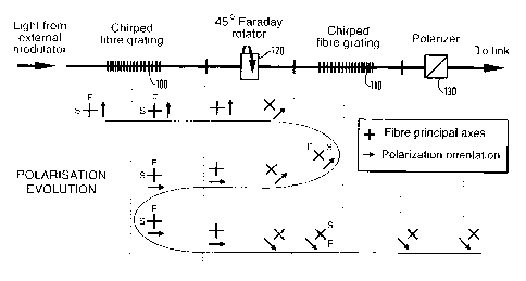
A chirped optical fibre grating formed by impressing a chirped substantially
periodic refractive index variation on a
polarisation-maintaining optical fibre. The polarisation state of a laser
transmitter (10) is maintained through an external modulator (20) and a
polarisation
maintaining circulator (30) by the use of polarisation maintaining fibre
pigtails (40) aligned to one of the principal axes of high birefringence
optical fibre used to fabricate the dispersion compensating grating (50). On
reflection, light is output from the third port (60) of the circulator.
Since only one polarisation mode of the grating (50) is excited, the PMD in
the grating is eliminated. The polarisation maintaining circulator
(30) comprises input/output lenses (32) at each port, a polarisation beam
splitter (34) and a Faraday rotator (36). Light entering the circulator
at the input port is arranged to be in a polarisation that passes through the
polarisation beam splitter (34) towards the second port of the
circulator. The light is rotated by 45° in the rotator (36). The
grating (50) and the fibre pigtail at the second port of the circulator are
arranged with their principal axes rotated by 45° with respect to the
axes of the input to the circulator. Light reflected from the grating
is then further rotated by 45° by the rotator, into the polarisation
which is deverted by the polarisation beam splitter (34). This light is
therefore diverted to the third output (60) of the circulator. Another
embodiment in which two chirped gratings (100, 110) are formed in
high birefringence polarisation maintaining fibre with axes aligned, and a
45° Faraday rotator (120) is placed inbetween.


French Abstract

La présente invention concerne un réseau de diffraction à fibres optiques à modulation de fréquence ("chirpé") que l'on forme en imprimant une variation "chirpée" sensiblement périodique de l'indice de réfraction à une fibre optique à maintien de polarisation. On maintient l'état de polarisation d'un émetteur laser (10) au travers d'un modulateur externe (20) et d'un circulateur à maintien de polarisation (30) en utilisant des fibres amorces à maintien de polarisation (40), lesquelles sont alignées dans l'un des axes principaux d'une fibre optique à forte biréfringence utilisée pour la fabrication du réseau de diffraction compensateur de dispersion (50). La lumière réfléchie sort par la voie 3 (60) du circulateur. Etant donné que seul un mode de polarisation du réseau de diffraction (50) est excité, la dispersion modale de polarisation du réseau de diffraction est éliminée. Le circulateur à maintien de polarisation (30) comprend des lentilles d'entrée/sortie (32) dans chaque voie, un diviseur de faisceau de polarisation (34) et un rotateur de Faraday (36). La lumière qui entre dans le circulateur par la voie d'entrée est amenée dans un faisceau de polarisation qui passe au travers du diviseur de faisceau de polarisation (34) vers la voie 2 du circulateur. La lumière subit une rotation de 45 DEG C dans le rotateur (36). Dans la voie 2 du circulateur, le réseau de diffraction (50) et la fibre amorce sont disposés de manière que leurs axes principaux présentent une rotation de 45 DEG C par rapport aux axes d'entrée du circulateur. La lumière réfléchie par le réseau de diffraction subit encore une rotation de 45 DEG C dans le rotateur, de manière qu'elle vient se placer dans le faisceau de polarisation qui est dévié par le diviseur de faisceau de polarisation (34). Cette lumière est de la sorte déviée vers la voie 3, voie de sortie (60) du circulateur. Selon un autre mode de réalisation, on forme deux réseaux de diffraction "chirpés" (100, 110) dans une fibre à maintien de polarisation à forte biréfringence dont les axes sont alignés, et l'on place un rotateur de Faraday (120) de 45 DEG C entre eux.

Claims

Note: Claims are shown in the official language in which they were submitted.


8
CLAIMS
1. An optical fibre transmission system, comprising:
an optical transmitter for generating light;
a dispersive optical fibre link optically coupled to the optical transmitter,
for transmitting the light generated by the optical transmitter; and
chirped optical fibre grating optically coupled to the optical transmitter
and to the dispersive optical fibre link to provide at least a partial
dispersion
compensation to the light generated by the optical transmitter, before the
light is
transmitted in the dispersive optical fibre link;
wherein the chirped optical fibre grating comprises a polarisation-
maintaining optical fibre having a chirped refractive index variation.
2. An optical fibre transmission system according to claim 1, further
comprising a polarisation-maintaining optical circulator having at least
first,
second and third input/output ports, the first port being optically connected
to the
optical transmitter, the second port being optically connected to the chirped
optical fibre grating, and the third port being optically connected to the
dispersive optical fibre link.
3. An optical fibre transmission system according to claim 1, wherein said
chirped optical fibre grating is a first chirped optical fibre grating
comprising a
first polarisation-maintaining optical fibre having a chirped refractive index
variation and having one of its principal axes aligned with the light
generated by
the optical transmitter; and
wherein the optical fibre transmission system further comprises:
a second chirped optical fibre grating positioned between the first chirped
optical fibre grating and the dispersive optical fibre link, the second
chirped
optical fibre grating comprising a second polarisation-maintaining optical
fibre
having a chirped refractive index variation and having principal axes rotated
by
about 45° with respect to the principal axes of the first chirped
optical fibre
grating; and


9
a polarisation rotator of approximately 45° positioned between the
first
and the second chirped optical fibre gratings.
4. An optical fibre transmission system according to claim 3, further
comprising an optical polariser positioned between the second chirped optical
fibre grating and the dispersive optical fibre link.
5. The optical fibre transmission system of claim 1, wherein the chirped
optical fibre grating has a principal axis substantially aligned with a
polarisation
axis of the light generated by the optical transmitter.
6. The optical fibre transmission system of claim 2, wherein the
polarisation-maintaining optical circulator comprises:
a polarisation beam splitter adapted to transmit light having a first
polarisation from the first port to the second port and to reflect light
having a
second polarisation from the second port to the third port; and
a polarisation rotator positioned between the polarisation beam splitter
and the second port.
7. An optical fibre transmission system according to claim 1, wherein the
chirped optical fibre grating is arranged such that the light emitted by the
optical
transmitter is reflected by the chirped optical fibre grating before being
transmitted into the dispersive optical fibre link.
8. An optical fibre transmitter unit comprising:
an optical transmitter for generating light; and
a chirped optical fibre grating optically coupled to the optical transmitter
to provide at least partial dispersion compensation to the light generated by
the
optical transmitter, wherein the chirped optical fibre grating comprises a
polarisation-maintaining optical fibre having a chirped refractive index
variation.
9. The optical fibre transmitter unit of claim 8, further comprising a
polarisation-maintaining optical circulator having at least first, second and
third


10

input/output ports, the first port being optically connected to the optical
transmitter, the second port being optically connected to the chirped optical
fibre
grating, and the third port being optically connected to an output of the
transmitter unit.

10. The optical fibre transmitter unit of claim 8, wherein the chirped optical
fibre grating comprises:
a first chirped optical fibre grating comprising a first polarisation-
maintaining optical fibre having a chirped refractive index variation and
having
one of its principal axes aligned with the light generated from the optical
transmitter; and
wherein the optical fibre transmission unit further comprises:
a second polarisation-maintaining optical fibre having a chirped
refractive index variation and having principal axes rotated by about
45° with
respect to the principal axes of the first chirped optical fibre grating; and
a polarisation rotator of approximately 45° positioned between the
first
and the second chirped optical fibre gratings.

11. The optical fibre transmitter unit of claim 10, further comprising an
optical polariser positioned after the second chirped optical fibre grating.

12. The optical fibre transmitter unit of claim 8, wherein the chirped optical
fibre grating is arranged such that the light emitted by the optical
transmitter is
reflected by the chirped optical fibre grating before being transmitted into a
dispersive optical fibre link.

13. A method of inputting light into a dispersive optical fibre link
comprising
the steps of:
providing light in a polarized state from an optical transmitter;
providing at least partial dispersion compensation to the light with a
chirped optical fibre grating formed of polarisation-maintaining optical fibre
having a principal axis substantially aligned with a polarisation axis of the
polarised state of the light from the optical transmitter; and
inputting the light after the at least partial dispersion compensation into a
dispersive optical fibre link.


Description

Note: Descriptions are shown in the official language in which they were submitted.

1015202530W0 98/08121CA 02264878 1999-02-23 ,PCT/GB97/0\2l001OPTICAL DISPERSION COMPENSATION This invention relates to optical dispersion compensation.Long distance transmission at 10 Gbit/s over standard telecommunicationsfibre is of great interest because of the large base of such fibres already installed inthe ground currently supporting low bit—rate systems.The low loss of these already installed fibres, together with the readyavailability of erbium doped fibre amplifiers (EDFAS), make the 1.55pm window anattractive wavelength region of operation. Unfortunately, however, the groupvelocity dispersion of these fibres is relatively large within this window, whichseverely limits the transmission distances achievable unless compensating techniquesare employed.Of the variety of methods which have been suggested thus far to solvethisproblem, linearly chirped fibre gratings as dispersion compensators [1, 2] arepotentially very attractive, as they are compact, totally passive, and relatively simpleto fabricate.Progress in the development of fibre gratings has been rapid in the last fewyears, especially with the introduction of the phase mask technique [3, 4], whichprovides a high degree of reproducibility in the gratings fabricated, as well asrelaxing the tolerances on the fabrication set-up. In addition, longer fibre gratingsare more readily realised with this approach [5, 6] than with the holographictechnique [7]. This is a crucial factor in dispersion compensation where themaximum compensatable distance is expected to scale directly with the grating length.Reports of experimental demonstrations of fibre compensation over standard fibrelinks, from l60km [8], 220km [9], to 270km [10, 11], were accomplished withgratings 4cm to 12cm long. With 10cm long phase masks now commerciallyavailable, and even longer masks a likely prospect in the near future, fibre gratingscapable of compensating over wide optical bandwidths and much longer distancesshould be feasible.Recently, it has been experimentally demonstrated that dispersioncompensation to 400km of standard single mode fibre is possible, with a 3 dB powerpenalty, using a 10cm long chirped fibre grating and an unchirped externally1015202530CA 02264878 1999-02-23‘ 7 ‘ w 1 \ - 3-o u \* , . ..‘2.3 . 3 .3 \ ., 5y ..modulated transmitted [12]. In separate experiments ‘using a chirpea externallymodulated transmitter, transmission over 403krn with negligible penalty has beendemonstrated and it has been shown that up to 537krn is possible with the use of twochirped gratings cascaded together [13].Reference [15] discloses a non-chirped grating written in an elliptical corefibre.This invention provides a chirped optical fibre grating, characterised in thatit is formed by impressing a chirped substantially periodic refractive index variationon a polarisation-maintaining optical fibre.This invention also provides an optical fibre transmission system comprising:an optical transmitter;a dispersive optical fibre link; anda chirped optical fibre grating connected at or near the input of the link toprovide at least partial dispersion compensation to the light launched along the link;characterised in that the grating is formed of polarisation-maintaining opticalfibre having a principal axis substantially aligned with a polarisation axis of light tobe transmitted through the link.The invention recognises that a dependence of system sensitivity on the inputpolarisation state to the grating can occur, due to polarisation mode dispersion (PMD)in linearly chirped dispersion compensating fibre gratings, and that this can give riseto a deterioration in the performance of optical transmission systems relying on suchgratings for fibre dispersion compensation.The invention addresses this problem by providing a polarisation-maintainingoptical fibre grating, e.g. a chirped grating for dispersion compensation. The axesof the polarisation maintaining fibre of the grating can then be aligned with apolarisation axis of the light to be transmitted through a fibre transmission system.The skilled man will understand that the term "polarisation maintaining fibre"refers to optical fibre having an optically asymmetric cross section, and typically abirefringence of greater than about 10‘.The invention will now be described by way of example only with referenceto the accompanying drawings in which:Figure 1 is a schematic graph showing the reflection and time delaycharacteristics of a conventional chirped optical fibre grating;Figures 2a and 2b are schematic graphs illustrating the reflection and time1015202530WO 98/08121CA 02264878 1999-02-23PCT/GB97/021003delay characteristics for such a grating written into a fibre with a birefringence of105;Figure 3 schematically illustrates an optical transmission system incorporatingpolarisation mode dispersion compensation;Figure 4 schematically illustrates another optical transmission systemincorporating polarisation mode dispersion compensationThe measured reflectivity and dispersion characteristics of a typical(conventional) chirped fibre grating are shown in Figure 1. To fabricate thisexample, a 10cm long uniform phase mask from QPS Technology was used.Apodisation and chirping of the grating was accomplished during the writing processusing the moving fibre—scanning beam technique [14], with a cosine apodisationprofile being adopted to reduce excessive ripples in the refection/dispersion spectra‘.This example grating exhibits a peak reflectivity of -50%, 3 dB bandwidth of0.12 nm and 5400 ps/nm dispersion. The grating is thus able to compensate fordispersion of 320km of standard single mode fibre (17 ps/nm.km) [13]. Thesemeasurements, although made with a polarised tunable laser, employed a polarisationinsensitive receiver and are thus insensitive to and do not reveal the PMD in thegrating.All optical fibres exhibit a degree of birefringence B, due to slight coreelipticity or anisotropic stress which gives rise to a difference between the refractiveindex and thus the mode propagation constants of the two principal axis, the fast andslow axes. The birefringence is defined as the difference between the mode indicesns and 11, for the slow and fast axisB = An = n,-nfFor standard optical fibre B is typically in the range -10‘5 - 10“" whilst in highbirefringence, polarisation maintaining fibre it can be as high as -103. The effect offibre birefringence on a chirped fibre grating is to split the reflection spectra for thefast and slow axis by A>\=2BA=B>\/n. Here A is the grating pitch, >\ the gratingcentral wavelength and n the average mode index.This effect is indicated schematically in Figures 2a and 2b, which areschematic graphs illustrating the reflection and time delay characteristics for such agrating written into a fibre with a birefringence of 10'5.'1015202530CA 02264878 1999-02-23W0 98/03121 PCT/GB97/021004As a result of the PMD, the time delay (dispersion) curves are wavelengthshifted for the two polarisations.The PMD is given by PMD=A)\D=2BAD=B)\D/n where D is the gratingdispersion.In this case the PMD would be -60ps which is significant compared to the bitperiod (100ps for a l0Gbit/s non-return to zero, NRZ system). As a rule of thumbfor reliable system operation, the total link PMD should be less than 1/ 10th of the bit-period. Taking into account the PMD of other components in the link fabricating thegrating in high quality fibre with low B of ~10‘, as in references 12 and 13, will notbe sufficient for long term reliable system operation since the input polarisation stateto the grating may vary over time. The problem will be even worse for longertransmission distances where the dispersion and thus PMD of the grating will belarger.It has thus been recognised that PMD in linearly chirped fibre gratings islikely to be a severe limitation to their future application.This problem is overcome in the present embodiments of the invention byfabricating the grating in high birefringence polarisation maintaining fibre such asFibrecore Bow-Tie fibre or Fujikura Panda fibre.In a first embodiment shown schematically in Figure 3, the polarisation stateof a laser transmitter 10 is maintained through an external modulator 20 and apolarisation maintaining circulator 30 by the use of polarisation maintaining fibrepigtails 40 aligned to one of the principal axes of high birefringence optical fibre usedto fabricate the dispersion compensating grating 50. On reflection, light is outputfrom the third port 60 of the circulator. Since only one polarisation mode of thegrating 50 is excited, the PMD in the grating is eliminated.The polarisation maintaining circulator 30 comprises input/output lenses 32 ateach port, a polarisation beam splitter 34 and a Faraday rotator 36. Light enteringthe circulator at the input port (shown on the left in Figure 3) is arranged to be in apolarisation that passes through the polarisation beam splitter 32 towards the secondport of the circulator (on the right in Figure 3). The light is rotated by 45° in therotator 36. The grating 50 and the fibre pigtail at the second port of the circulatorare arranged with their principal axes rotated by 45° with respect to the axes of the1015202530W0 98/08121CA 02264878 1999-02-23PCT/GB97/021005input to the circulator. Light reflected from the grating is then further rotated by 45°by the rotator, into the polarisation which is diverted by the polarisation beam splitter34. This light is therefore diverted to the third, output port 60 of the circulator.Another embodiment could instead use a commercially available polarisationmaintaining circulator such as the Model SPFC 210071000 from E-Tek DynamicsInc, San Jose, California.Figure 4 schematically illustrates another embodiment in which two chirpedgratings 100, 110 are formed in high birefringence polarisation maintaining fibre withaxes aligned, and a 45° Faraday rotator 120 is placed in-between.With a grating fibre birefringence of lO‘3, the reflection spectra for the fastand slow axes are separated by -1 nm; thus for grating and signal bandwidths lessthan 1 nm, and with the signal wavelength positioned correctly (i.e. substantiallyaligned) with respect to one or other of the two spectra, the hi—bi fibre gratings areeffectively transparent for one polarisation state of the light, along say, the fast axis,but reflecting for light on the other axis.The principle of operation of this configuration is then simply explained asfollows, assuming that in this case the transmitter wavelength is selected so that thefast axis is transmitting and the slow axis reflecting.Light from the external modulator (not shown in Figure 4), polarised along,say, the fast-axis, is first transmitted through the grating 100, undergoes a 45°rotation by the Faraday rotator 120 and hence is launched into the slow-axis ofgrating 2. It is thus reflected by grating 110, and undergoes a further 45° rotation tonow be launched into the slow-axis of grating 100, where it is reflected. Passingonce more through the Faraday rotator, it gets launched into the fast-axis of grating110, which is transparent to the signal, and hence the signal is finally transmitted outinto the system.Light initially launched along the slow axis of the grating 100 is simplyreflected back from the grating 100.An output polariser 130 is used to block any output light in the unwantedpolarisation, and therefore to improve further the performance of the system, becausethe polarisation rejection by the grating is not 100% efficient.With this configuration, the total dispersion compensated is the sum of theCA 02264878 1999-02-23W0 98/0812] PCT/GB97/021006dispersion of the two gratings 100 and 110.CA 02264878 1999-02-237PUBLICATION REFERENCES[1] F. Ouellette, ‘Dispersion cancellation using linearly chirped Braggigrating filters inoptical waveguides’, Opt. Lett., vol. 12. pp. 847-849,, 1987.[2] K. 0. Hill, F. Bilodeau, B. Malo, T. Kitagawa, S. Theriault, D. C. Johnson and I.Albert. 'Chirped in-fiber Bragg gratings for compensation of optical-fiber dispersion’, Opt.Lett.. vol. 19. pp. 1314-1316, 1994.[3] 0. Hill. B. -.V1alo, F. Bilodeau. D. C. Johnson and 1. Albert, "Bragg gratingsfabricated in monomode photosensitive optical fiber by UV exposure through a phase mask’,Opt. Lett., vol. 62. pp. 1035-1037, 1993.[-1.] D. Z. Anderson. V. Mizrahi, T. Erdogan and A. E. White, 'Production of in-fibergratings using a diffractive optical element‘, Electron. Lett., vol. 29, pp. 566-568. 1993.[5] J. Martin and F. Ouellette. ‘Novel writing technique of long and highly reflective in-fibre gratings’. Electron. [_ett., vol. 30. pp. 811-812, 1994.[6] H. N. Rourke, S. R. Baker, K. C. Byron. R. S. Baulcomb, S. ~.V1. Ojha and S.Clements, 'Fabrication and characterisation of long. narrowband fibre gratings by phase maskscanning’, Electron. Lett.. vol. 30, pp. 1341-1342, 1994.[7] G. Meltz, W. W. —.Vlorey and W. H. Glenn. ‘Formation of Bragg gratings in opticalfibers by a transverse holographic method’, Opt. Lett., vol. 14, pp. 823-825, 1989.[8] D. Garthe. R. E. Epworth, W. S. Lee, A. Hadjifotiou, C. P. Chew, T. Bricheno, A.Fielding, H. Rourke. S. R. Baker. K. C. Byron. R. S. Bauicomb, S. M. Ohja and S.Clements. ‘Adjustable dispersion equaliser for 10 and 20 Gbit/s over distances up to 160 km’,Electron. l_ett., vol. 30, pp. 2159-2160, 1994.[9] R. 1. Laming, N. Robinson. P. L. Scrivener, 1V1. N. Zervas, S. Barcelos. L. Reekieand J. .-\. Tucknott, ‘A dispersion tunable grating in a 10 Gbit/s 100-220 km step index fiberlink’. lEEE Plioton. Teclznol. Lett.. to be published.[10] P. A. Krug, T. Stephens, G. Yoffe. F. Ouellette, P. Hill and G. Dhosi. '270 kmtransmission at 10 Gbit/s in non—dispersion shifted fibre using an adjustably chirped 120 mmtibre Bragg grating dispersion compensator’, C0/"If. Opt. Fiber Comm, paper PDP27. 1995.[11] F. Ouellette. P. A. Krug, T. Stephens, G. Dhosi and B. Eggleton. Broadband andWD.\l dispersion compensation using chirped sampled fibre Bragg gratings‘. Electron. Lett..vol. 31. pp. 899-900, 1995.[12] W. H. Loh. R. 1. Laming. Gu.Z\«1. N. Zervas, M. J. Cole, T. Widdowson and A.D. Ellis. '10 cm chirped fibre Bragg grating for dispersion compensation at 10 Gbit/s over 400krn or‘ non-dispersion shifted Fibre’. Electron. Lett.. Vol. 31. 00. 2203-220-1.1995.[13] W. H. Loh. R. 1. Laming. N. Robinson. A. Cavaciuti. F. Vaninetti. C. J. Anderson._\l. N. Zervas and -.\l. 1. Cole, ‘Dispersion compensation over distances in excess of 500 for 10 G'oit.’s systems using chirped fibre gratings‘. submitted to IEEE Photonics TechnologyLetters. .-[l~!] -.\l. 1. Cole. W. H. Loh. R. 1. Laming. M. N. Zervas and S. Barcelos. '.\lovingtibre. phase mask-scanning beam technique for enhanced tlexibility in producing fibre gratingswith uniform phase mask’, Electron. Lett, vol. 31. pp. 1488-1490, 1995.[15] P. Niay et a1, "Polarisation Selectivity of Gratings Written in Hi'Bi Fibres bythe External Method", IEEE Photonics Technology Letters, vol. 7, pp. 391-393 1995
Representative Drawing
A single figure which represents the drawing illustrating the invention.
Administrative Status

For a clearer understanding of the status of the application/patent presented on this page, the site Disclaimer , as well as the definitions for Patent , Administrative Status , Maintenance Fee  and Payment History  should be consulted.

Administrative Status

Title Date
Forecasted Issue Date 2006-10-31
(86) PCT Filing Date 1997-08-04
(87) PCT Publication Date 1998-02-26
(85) National Entry 1999-02-23
Examination Requested 2002-07-23
(45) Issued 2006-10-31
Expired 2017-08-04

Abandonment History

There is no abandonment history.

Payment History

Fee Type Anniversary Year Due Date Amount Paid Paid Date
Registration of a document - section 124 $100.00 1999-02-23
Application Fee $300.00 1999-02-23
Maintenance Fee - Application - New Act 2 1999-08-04 $100.00 1999-07-26
Maintenance Fee - Application - New Act 3 2000-08-04 $100.00 2000-07-20
Maintenance Fee - Application - New Act 4 2001-08-06 $100.00 2001-07-19
Maintenance Fee - Application - New Act 5 2002-08-05 $150.00 2002-07-18
Request for Examination $400.00 2002-07-23
Maintenance Fee - Application - New Act 6 2003-08-04 $150.00 2003-07-22
Maintenance Fee - Application - New Act 7 2004-08-04 $200.00 2004-07-21
Maintenance Fee - Application - New Act 8 2005-08-04 $200.00 2005-07-20
Final Fee $300.00 2006-07-18
Maintenance Fee - Application - New Act 9 2006-08-04 $200.00 2006-07-31
Maintenance Fee - Patent - New Act 10 2007-08-06 $250.00 2007-07-25
Maintenance Fee - Patent - New Act 11 2008-08-04 $250.00 2008-07-17
Maintenance Fee - Patent - New Act 12 2009-08-04 $250.00 2009-07-21
Maintenance Fee - Patent - New Act 13 2010-08-04 $250.00 2010-07-19
Maintenance Fee - Patent - New Act 14 2011-08-04 $250.00 2011-07-18
Maintenance Fee - Patent - New Act 15 2012-08-06 $450.00 2012-07-17
Maintenance Fee - Patent - New Act 16 2013-08-05 $450.00 2013-07-17
Maintenance Fee - Patent - New Act 17 2014-08-04 $450.00 2014-07-29
Maintenance Fee - Patent - New Act 18 2015-08-04 $450.00 2015-08-03
Maintenance Fee - Patent - New Act 19 2016-08-04 $450.00 2016-08-01
Owners on Record

Note: Records showing the ownership history in alphabetical order.

Current Owners on Record
PIRELLI CAVI E SISTEMI S.P.A.
Past Owners on Record
LAMING, RICHARD IAN
LOH, WEI-HUNG
Past Owners that do not appear in the "Owners on Record" listing will appear in other documentation within the application.
Documents

To view selected files, please enter reCAPTCHA code :


To view images, click a link in the Document Description column. To download the documents, select one or more checkboxes in the first column and then click the "Download Selected in PDF format (Zip Archive)" or the "Download Selected as Single PDF" button.

List of published and non-published patent-specific documents on the CPD .

If you have any difficulty accessing content, you can call the Client Service Centre at 1-866-997-1936 or send them an e-mail at CIPO Client Service Centre.


Document
Description 
Date
(yyyy-mm-dd) 
Number of pages   Size of Image (KB) 
Representative Drawing 2006-10-04 1 10
Cover Page 2006-10-04 2 61
Representative Drawing 1999-05-07 1 9
Claims 1999-02-23 2 50
Drawings 1999-02-23 4 75
Abstract 1999-02-23 1 65
Description 1999-02-23 7 351
Cover Page 1999-05-07 2 98
Claims 2005-03-24 3 150
Correspondence 1999-04-20 1 31
PCT 1999-02-23 14 538
Assignment 1999-02-23 4 107
Assignment 2000-02-09 2 70
Prosecution-Amendment 2002-07-23 1 27
Prosecution-Amendment 2004-10-04 2 57
Prosecution-Amendment 2005-03-24 5 229
Correspondence 2006-07-18 1 38