Note: Descriptions are shown in the official language in which they were submitted.
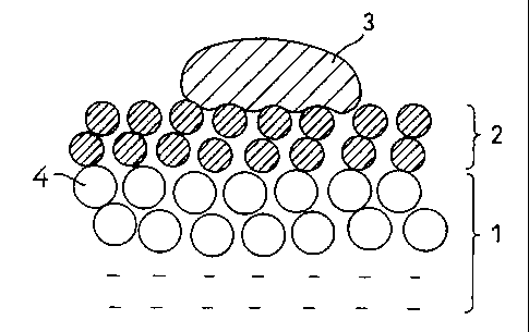
?CA 02265479 1999-03-08DESCRIPTIONDENITRATION CATALYST, PROCESS FOR PREPARING THE SAME, ANDEXHAUST GAS PURIFICATION METHODTECHNICAL FIELDThe present invention relates to a<denitration catalyst,a process for preparing the same, and an exhaust gaspurification method, and in particular to a denitrationcatalystforefficientcatalyticreduction,withammonia(NHQ,of:nitrogen.oxides (NOX) containediJ1an.exhaust gas containinghighly deliquescent salts as dust, such as in an oilâfiredboiler exhaust gas, a combustion exhaust gas from wood waste,wood as fuels, and in a furnace for refuse.BACKGROUND ARTNOx in flue gas discharged from a power station or anincinerator is a substance causing photochemical smog and acidrain, and a flue gas denitration method by selective catalyticreduction with ammonia as a reducing agent is used widely asa method for effective removal of NOX mainly in thermal powerstations. As the catalyst, a titanium oxide (TiO2) typecatalyst containing vanadium (V), molybdenum (M0) or tungsten(W) as the active component is used, and particularly thecatalyst containing vanadium as one of the active componentsis highly reactive and can be used at low temperatures (e.g.in a temperature range of 300 °C or less), so it becomes themainstream of the denitration catalyst at present (JapanesePatent Application Laid-Open No. 50â12868lA and the like).Thecatalystix)thepriorartnmntionedabovehassuperior?CA 02265479 1999-03-08characteristics by which very high degrees of denitration canbe achieved in purification of combustion exhaust gases suchas gas-fired, oil-fired or coalâfired fuel exhaust gases, butno adequate measures have been taken to purify an exhaust gasfrom wood waste and wood as fuels abundant in North Europe orthe like area and an exhaust gas containing a large amount ofdeliquescent salts in ash fronlan incinerator and the like, andthere has been the problem that the degrees of denitration arelowered with time.Fig. 7 shows the degrees of denitration and the changeof the amount of an alkali accumulated in the conventionaldenitration catalyst in the case (A) where the conventionalcatalyst was exposed to a wood-fired boiler combustion exhaustgas as an example of application to an exhaust gas containinga large amount of deliquescent salts and the case (B) where thecatalyst was exposed to a coalâfired boiler exhaust gas as anexample not containing deliquescent salts. In the case (A) ofthe wood-fired boiler containing a large amount of potassiumcarbonate as a<deliquescent alkali metal salt, there occurs thephenomenon in which the amount of the alkali in the catalystis increased and the degree of denitration rapidly decreases.Such deterioration of the denitration catalyst by thealkali metal salt also occurs where an incinerator exhaust gasor a high-sulfur oil-fired boiler exhaust gas is to bedenitrated, thus greatly preventing practical application ofthe low-temperature denitration method to such exhaust gases.It was found that the above deterioration by the highlydeliquescent salt is caused by inclusion, in ash, of (1)?CA 02265479 1999-03-08potassium carbonate in the case where wood waste is used as thefuel, (2) calcium chloride or sodium chloride in the case ofrefuse combustion exhaust gas, and (3) sodium sulfate andpotassium sulfate in the case of high-sulfur oilâfired boilers.Accordingly, it is believed that although the alkali metal saltsin ash differ depending on the type of exhaust gas as describedabove, any deterioration of the catalyst during lowâtemperaturedenitration is caused by the common mechanism in which thealkali metals and alkaline earth metal salts contained in ashabsorb moisture to deliquesce to form a liquid in the step oftemperature raising when a denitration apparatus starts orstops, so that the fluid of the metal salts penetrates into thecatalyst to cause the clogging of pores therein and todeteriorate the active site.To prevent the deterioration of the denitration catalystby such fluid having deliquesced, it is necessary to physicallyprevent the fluid that has deliquesced from entering thedenitration catalyst.The present invention provides a highly durabledenitration catalyst which is prevented from undergoing rapiddeterioration upon deliquescence of salts, which deteriorationoccurs in the case of denitration of an exhaust gas containingash having a wide variety of deliquescent salts as describedabove, a process for preparing the the denitration catalyst,and a method for purification of an exhaust gas by use of thesame.DISCLOSURE OF THE INVENTIONThe inventions claimed in this patent application are as...â...~..............._..._....,. .- .. .?CA 02265479 1999-03-08follows:(1) A.denitration.catalyst for use in the reduction, withammonia, of nitrogen oxides contained in an exhaust gascontaining highly deliquescent salts as dust, which bears onthe surface of the denitration catalyst a porous coating layerof a waterârepellent organic resin, a porous coating layer ofa mixture of a waterârepellent organic resin with inorganicoxide particles, or a porous coating layer of a mixture of awaterârepellent organic resin with catalyst componentparticles.(2) A.denitration catalyst according to (1), wherein thewaterârepellent organic resin comprises at least one offluorine resin, polyamide resin, acrylic resin and siliconresin.(3) A denitration catalyst according to (l) or (2),wherein the catalyst component particles consist of titaniumoxide, molybdenum oxide or tungsten oxide and vanadium.oxide.(4) A denitration catalyst according to any one of (1)to (3), wherein the denitration catalyst is a catalyst moldedbody containing titanium oxide, molybdenum oxide or tungstenoxide, and vanadium oxide.(5) A denitration catalyst according to any one of (1)to (3), wherein the denitration catalyst is a plate-shapedmolded body comprising a composition mainly composed oftitanium oxide and molybdenum oxide or tungsten oxide, andvanadium oxide, filled between network inorganic fibersubstrates and within the nets thereof.(6) A process for preparing a denitration catalyst, which?CA 02265479 1999-03-08comprises permitting an aqueous slurry or emulsion.of at leastone resin composition selected from the group consisting of awaterârepellentorganicresin,anuxtureofthevmter-repellentorganic resin and inorganic oxide particles, and a mixture ofthe waterârepellent organic resin and catalyst componentparticles to be coated on, or to adhere by a spray to the surfaceof a denitration catalyst and then evaporating its water to formtheir porous coating layer.(7) A process for preparing a denitration catalystaccordingto(6),whereinthedenitrationcatalystisacntalystmolded body containing titanium oxide and molybdenum oxide ortungstenoxide,andvanadiumoxide,andthecatalystmoldedbodyis previously moistened to form the porous coating layer in awet state.(8) A process for preparing a denitration catalyst, whichcomprises coating an aqueous dispersion containing a water-repellent organic resin at a low concentration onto the surfaceof a denitration catalyst for use in the ammonia reduction ofnitrogen oxides contained in an exhaust gas containing highlydeliquescent salts as dust, drying the coating, further coatingthe dried coating with an aqueous dispersion containing awaterârepellent organic resin at a higher concentration thanthe above concentration, and then drying the coating to forma porous coating layer of the waterârepellent organic resin.(9) A process for preparing a denitration catalystaccording to (8), wherein the concentration of the water-repellent organic resin in the lowâconcentration aqueousdispersion ranges from 5 to 30% by weight.?CA 02265479 1999-03-08(10) A process for preparing a denitration catalystaccording to (8), wherein the concentration of the water-repellent organic resin in the low-concentration aqueousdispersion ranges from 10 to 20% by weight.(11) A process for preparing a denitration catalystaccording to (8), wherein the concentration of the water-repellent organic resin in the high-concentration aqueousdispersion ranges from 30 to 60% by weight.(12) A process for preparing a denitration catalystaccording to any one of (8) to (11) , wherein the water-repellentorganic resin comprises at least one of fluorine resin,polyamide resin, acrylic resin and silicon resin.(13) A process for preparing a denitration catalystaccording to any one of (8) to (12), wherein the denitrationcatalyst is a catalyst molded body containing titaniuntoxide,molybdenum oxide or tungsten oxide and vanadium oxide.(14) A denitration catalyst according to any one of (8)to (12), wherein the denitration catalyst is a plate-shapedmolded body comprising a composition mainly composed oftitanium oxide and molybdenum oxide or tungsten oxide, andvanadium oxide, having filled between network inorganic fibersubstrates and within the nets thereof.(15) A denitration catalyst prepared by a processaccording to any one of (8) to (14).(16) A method for purification of an exhaust gas, whichcomprisesreduction,withammonia,ofnitrogenoxidescontainedin an exhaust gas containing highly deliquescent salts as dustby use of a denitration catalyst according to any one of (1)?CA 02265479 1999-03-08to (15).BRIEF DESCRIPTION OF THE DRAWINGSFig. 1 is a drawing showing the working effect of thedenitration catalyst of the present invention; Fig. 2 is adrawing showing the working effect of a conventional catalyst;Fig. 3 is a drawing showing the surface of the denitrationcatalyst according to one example of the present invention; Fig.4 is a drawing showing the surface of the denitration catalystcoated with a low-concentration dispersion; Fig. 5 is a drawingshowing the denitration catalyst coated with a high-concentration dispersion; Fig. 6 is a drawing showing thesurface of the denitration catalyst coated repeatedly with thelowâconcentration dispersion; and Fig. 7 is a drawing showingthe problem of the conventional catalyst.In the drawings, 1 means the denitration catalystcomponent layer; 2, a water-repellent coating layer; 3, analkalithathasdeliquesced;4,denitrationcatalystparticles;10, the denitration catalyst; 11, the surface of the catalyst;12 and 12a, cracks; 13, 13a, 14 and 14a, coating layers; and16, 16a, 17 and 18, penetration layers.BEST MODE FOR CARRYING OUT THE INVENTIONHereinaftery thepresentinventionijsdescribedixidetailby reference to the drawings.Fig. 1 is a drawing showing the working effect of thedenitration catalyst of the present invention, and Fig. 2 isadrawingshowingtheworkingeffectofaaconventionalcatalyst.In Fig. l, the denitration catalyst of the presentinvention bears, on the surface of the denitration catalyst?CA 02265479 1999-03-08component layer 1 consisting of the denitration catalystparticles 4, the water-repellent coating 2 selected from aporous coating layer of a water-repellent organic resin, aporous coating layer of alnixture of a1Naterârepellent organicreshiwithinorganicoxideparticles,oraaporouscoatinglayerof a mixture of a water-repellent organic resin with catalystcomponent particles.In general, when the denitration catalyst is used in anexhaust gas containingâhighlyrdeliquescent alkali.metal salts,dust adheres as particles to the surface of the catalyst.The alkali metal salts adhered to the catalyst absorbmoisture in the atmosphere or exhaust gas to deliquesce andenter the catalyst when the apparatus stops or starts. Whenthe alkali salts adhered to the surface of the denitrationcatalyst component layer 1 deliquesce, alkali 3 deliquescedpenetrates through the spaces among the denitration catalystparticles 4 into the inside of the catalyst as shown in Fig.2, thus causing the clogging of pores and simultaneouslyreactingwiththecatalystcomponenttodenaturetheactivesiteand to deteriorate the catalyst. By way of example, theconventional catalyst is embedded in potassium carbonate, andafter maintained for one day under high humidity, the catalystwas observed for the outer appearance, and as a result it wasfound that the potassium carbonate deliquesced and adhered tothe surface of the catalyst after the test. The catalyst wasdried, the salt deliquesced was removed therefrom, and theamount of potassium in the catalyst was determined. The resultindicated that the potassium accounted for several tens % by?CA 02265479 1999-03-08weight, and it was thus found that the potassium carbonateentered the inside of the catalyst.When the conventional catalyst is used in an exhaust gascontaining deliquescent salts as dust, the dust having adheredthereto deliquesces with water when the denitration apparatusstops or starts again, and the fluid of the dust transfers intothe catalyst to cause the reduction of the activity of thecatalyst.To the contrary, the denitration catalyst according tothe present invention bears the waterârepellent coating layer2 on the surface of the denitration catalyst component layer1, and this waterârepellent coating layer 2 has a large Contactangle to water, salts, so even if the alkali 3 deliquescedbecomes fluid to adhere to the surface of the catalyst, it isrepelled as shown in Fig. 1. Further, because of its surfacetension, the deliquescent substance cannot penetrate into theinside of the catalyst so it does not cause clogging of poresor deterioration of the catalyst resulting from denaturationof the active site. Further, the waterârepellent coating 2 isporous, repels fluid because of its surface tension, but canpass gases such as reactive gas, vapor through it, so it doesnot prevent the denitration reaction.On the other hand, the high\uaterârepellent effect of thesurface of the catalyst is achieved by forming a waterârepellentcoating layer having a sufficient thickness on the surface ofthe catalyst, but if the coating layer is too thick, thewater-repellent effect is raised, but the diffusion of anexhaust gas into the catalyst is prevented, so the denitration?CA 02265479 1999-03-08performance of the catalyst is easily lowered, and further alarge amount of the water-repellent component coated leads tohigher costs. Accordingly, it is preferable to reduce theamount of the water-repellent component coated.on the surfaceof the denitration catalyst. Further, if the surface of thecatalyst has a site where a coating layer of the water-repellentcomponent is not formed, the fluid of the alkali deliquescedpenetrates through such sites to cause the deterioratiorxof thecatalyst, so it is preferable to fornxa thin and dense coating.If a dispersion of a highâconcentration water-repellentcomponent is used to form the water-repellent coating layer onthe surface of the catalyst, a thin and uniform water-repellentcoating cannot be applied on the surface of the catalyst.Further, if a low-concentration dispersion is used, thereoccurs a site where a water-repellent coating layer is notformed on the surface of the catalyst and this site serves asa.path througfxwhich the alkali penetrates, so there is the casewhere the durability of the catalyst for a long period of timecannot be achieved.Fig. 4 is a drawing showing the surface of the catalystcoated with a low-concentration dispersion.In Fig. 4, when the low-concentration dispersion iscoated on the surface of the catalyst of the denitrationcatalyst 10, fine particles of the water-repellent component,along with the dispersion medium, penetrate through thecatalyst surface 11 and cracks 12 on the surface to the insideofthecatalyst,toformthepenetrationlayer16iJ1thecatalyst.Further, the coating layer 13 is formed on the surface of the10?CA 02265479 1999-03-08catalyst 11, but the coating layer 13 is thin and the amountof the water-repellent component carried is small, so thewater-repellent coating layer is not formed in crack 12 on thesurface of the catalyst. .Accordingly, the sufficientwater-repellent effect of the water-repellent coating layercannot be obtained, and the durability of the denitrationcatalyst 10 is lowered.Fig. 5 is a drawing showing the surface of the catalystcoated with a high-concentration dispersion.InE1g.£L whenthecatalystsurface]J.ofthedenitrationcatalyst 10 is coated with a highâconc. dispersion, thepenetration layer 17 is formed in the catalyst, and thedispersion medium selectively penetrates into the catalyst toform the thick coating layer 14a on the surface of the catalyst11, and further the cracks 12 on the surface of the catalystare filled with the water-repellent component. However,because the coating layer 14a is thick, the diffusion of anexhaust gas into the catalyst is prevented and the denitrationactivity is decreased. Further, the cracks 12a occur in thecoating layer 14a itself, and the cracks 12a serve as pathsthroughwhichthefluiddeliquescedpasses,thusdecreasingthedurability of the denitration catalyst 10.Fig. 6 is a drawing showing the surface of the catalystcoated repeatedly with a low-concentration dispersion.In Fig. 6, the surface of the catalyst 11 of thedenitration catalyst 10 is coated with a low-concentrationdispersion to form a thin water-repellent coating layer, andthereafter, it is further coated with the low-concentrationll?CA 02265479 1999-03-08dispersion.to forntthe coating layer 13a. However, even if thecatalyst is coated repeatedly with the low-concentrationdispersion, the dispersion penetrates through the crack 12 onthe surface of the catalyst 11 into the inside of the catalystto form the highâconcentration penetration layer 18 in thecatalyst, but the coating layer 13a cannot be formed in thecracks 2 on the surface of the catalyst.The present invention prevents the occurrence of theproblems described.above, and.it is preferable for improvementof the durability of the catalyst that an aqueous dispersioncontaining a water-repellent organic resin at a lowconcentration is coated and dried on the surface of thedenitration catalyst used for ammonia reduction of nitrogenoxides contained in an exhaust gas containing deliquescentsalts as dust, and then an aqueous suspension containing thewater-repellent organic resin at a higher concentration thanâthe above concentration is further coated and dried thereon toform a porous coating layer of the water-repellent organicresin.Fig. 3 is a drawing showing the surface of the denitrationcatalyst produced by the process described above.In Fig; 3, a low-concentration.dispersion is first coatedand dried on the surface of the catalyst 11 of the denitrationcatalyst 10 to form the thin water-repellent coating layer 13.In this step, the cracks 12 on the surface of the catalyst 11are not coated with the coating layer 13 (see Fig. 4). Then,the surface of the catalyst on which the coating 13 was formedis coated with a highâconcentration dispersion whereby the12?CA 02265479 1999-03-08coating layer 14 is formed. In this step, the dispersion mediumfor the high-concentration dispersion penetrates through thecrack 12 and a thin portion of the coating layer 13 into thecatalyst to form the penetration layer 16a, and fine particlesof the water-repellent component in the dispersion areaccumulated on the coating layer 13 and the crack 12 on whichthe lowâconcentration dispersion could not be formed, to formthe coating layer 14.In this manner, after the thin water-repellent coatingon the surface of the catalyst is formed from the low-concentration dispersion, then the highâconcentrationdispersion is coated thereon whereby the selective absorption,into the catalyst, of only the dispersion medium occurring oncoatingthehigh-concentrationdispersioncanlxaprevented,andthe thin coating layer can thereby be formed from the high-concentration dispersion. In this case, it is important toconfer water repellence on the surface of the catalyst bycoating the surface with the low-concentration dispersion anddrying it . By coating the high-concentration dispersion on thewater-repellent coating layer, the dispersion medium isabsorbed through cracks and thin portions of the initiallyformed coating layer, and simultaneously the water-repellentcomponent is selectively accumulated on such portions, to forma water-repellent aqueous coating, thus reducing the non-waterârepellent portion and forming the uniform and thincoating layer whereby the highly durable catalyst can beobtained.In the present invention, the water-repellent coating13?CA 02265479 1999-03-08layer can be given by drying the dispersion after coated, orby further calcination at a temperature of 100 to 380 °C afterdrying. The means for coating the dispersion are notparticularly limited, but can be effected by any means knownin the art. For example, mention is made of those by means ofbrush, roller, spray and the like or impregnation of thecatalyst with the dispersion.In the present invention, the denitration catalyst isprepared preferably by forming a composition containingtitanium oxide, tungsten oxide or molybdenum oxide, andvanadium oxide into a molded body in the form of plate, honeycomb,particle and the like. In particular, a denitration catalystof a plateâshaped molded body comprising a composition mainlycomposed of titanium oxide and molybdenum oxide or tungstenoxide, and vanadium oxide filled between network inorganicfibersubstratesandvuthinthenetsthereofispmeferablyused.The porous coating layer of a water-repellent organicresin is formed preferably by coating or spraying a slurryhaving fine particles of a water-repellent organic resinselected from fluorine resin, polyamide resin, silicon resinand acrylic resin.dispersed.inxnater, or by coating or sprayinga slurry having fine particles of the water-repellent organicresin and fine particles of inorganic oxides such as silica,titania dispersed together therein, or a slurry having fineparticles of the water-repellent organic resin and catalystcomponent particles dispersed therein. The term âfineparticlesâ refers not only to spherical fine particles but alsoto fine fibrousxnaterials such as fibrils. The size of the fine14?CA 02265479 1999-03-08particles is preferably 500 A or more so as not to penetrateinto fine pores in the catalyst to cause clogging of the pores.In the present invention, the catalyst componentparticles in the porous coating layer include particlesconsisting of a mixture of titanium oxide and tungsten oxideor molybdenum oxide, and vanadium oxide. Further, in thepresent invention, the catalyst component layer on which thecoating layer is formed is designed to have a two-layerstructure whose surface layer is a vanadium compound-freecatalyst component layer to further prevent it from being liableto the toxicity of alkali metal salts.Formatnniofthecoatinglayerisconductedusuallyaftercalcination of the catalyst, which.may be either in.a dry stateor in a wet state after moistened. In a wet state, there arethe advantages that penetration.ofâtheiNaterârepellent organicresin into the catalyst pores can be prevented due to water inthe catalyst pores and that the amount of the water-repellentorganic resin necessary for the coating is reduced. Even ifthe coating layer is formedcnithe surface of the catalyst, thiscoating layer is porous, repels a deliquescence fluid due toits surface tension, and can.pass gases such as exhaust gas andvapor through it, so this coating layer does not prevent thedenitration reaction.In the present invention, when a low-concentrationdispersion is previously coated to form a porous coating layer,the concentration of a water-repellent organic resin in thedispersion is preferably 5 to 30% by weight, more preferably10 to 20% by weight for coating properties and from an economical15?CA 02265479 1999-03-08viewpoint. The concentration of the water-repellent organicresinjJ1thehigh-concentrationchspersionsubsequentlycoatedis not particularly limited insofar as it is higher than theconcentration of the low-concentration dispersion, and itsconcentration is preferably 30 to 60% by weight for coatingproperties, coating uniformity and the like. It is preferableto select the concentration suitably depending on coatingconditions and waterârepellence required of the catalystsurface of the catalyst. Further, the dispersion can containother components in such a range as not to impair the objectof the present invention.According to the denitration catalyst of the presentinvention, even if deliquescent salts absorb moisture anddeliquesce in the step of temperature raising when a denitrationapparatus starts or stops, the porous coating layer of thewaterârepellent organic resin on the surface repels the saltsin a liquid form to prevent them from entering the catalystwhereby the catalyst is prevented from deterioration and theactivity thereof can thereby be maintained for a prolongedperiod of time.The temperature for use of the catalyst of the presentinvention subjected to waterârepellent treatment is thetemperature at which the waterârepellent organic resin is notmolten or burned; for example, if polytetrafluoroethylene isused as the fluorine resin, 350 °C or less is preferable.Hereinafter, the present invention is described in moredetail by reference to the Examples . In the Examples, â%â meansâ% by weightâ unless otherwise specified.16?CA 02265479 1999-03-08Example 12.5 kg of ammonium molybdate ((NH4)6Mo,02,,/4H20) ) , 2 .33 kgof ammonium methavanadate, 3.0 kg of oxalic acid, 4.8 kg ofinorganic fibers (trade name: Kaowool) and water were addedto 20 kg of titanium oxide powder, and these were kneaded ina kneader to prepare a substrate paste with a water content of33%.On the other hand, a network material having 1400 twistedfilaments of E glass fibers with a fiber diameter of 9 pmplainâwoven at a roughness of 10 filaments/inch was impregnatedwith a slurry consisting of 40% of titania, 20% of silica soland 1% of polyvinyl alcohol, and dried at 150 °C to make it rigidto give a catalyst substrate.The above substrate paste was placed between the twocatalyst substrates and passed through a pair of pressurerollers whereby a plate-shaped catalyst of 1.2 mm in thicknessconsisting of titanium oxide, molybdate oxide, and vanadiumoxide was obtained. It was airâdried for 12 hours in theatmosphere and calcined at 500°C for two hours.It was subjected to water-repellent treatment by sprayingit with fluorine resin aerosol (manufactured by 3M) and dryingit at 120 °C for one hour. The amount of this fluorine resincoated, as determined from the increase of the weight, was about0.5% of the weight of the catalyst.Example 22.5 kg of ammonium molybdate ((NH.,)5Mo,O2,/4H2O) ) , 2.33 kgof ammonium methavanadate, 3. 0 kg of oxalic acid and water wereadded to 20 kg of titanium oxide powder, and these were kneadedl7?CA 02265479 1999-03-08in a kneader to prepare a paste which was then granulated intoa tube of 3 mm in diameter. It was then dried in a fluidized-beddryer, calcined at 550°C for two hours, and then ground in ahammer mill whereby catalyst powder containing 50% or more ofl um or less particles was obtained.A suspension of a fluorine resin in water (trade name:Polyflon TFE dispersion, produced by Daikin Industries, Ltd.)in an amount of 1% relative to the catalyst was added to 10kgof catalyst powder and kneaded to give a paste with a watercontent of 60%.The resulting paste was coated by a brush on a plate-shaped catalyst prepared.in the same manner as in Exampleilanddried to be subjected to waterârepellent treatment. Thethickness of its waterârepellent coating was 0.05 mm.Example 3Water was added to a fluorine resin suspension (tradename: Polyflon TFE dispersion, produced.by Daikin Industries,Ltd.) and kneaded to give a slurry witrxa water content of 80%.The plate-shaped catalyst prepared in the same manner asinExample].wasimmersedixxtheresultingslurry,thendeprivedof the fluid present, and dried whereby a water-repellentcoatinglayerwasformed. Thethicknessofthevmterârepellentcoating layer was about 0.05 mm.Example 4The plate-shaped catalyst was subjected to water-repellent treatment in the same manner as in Example 3 exceptthat an acrylic resin emulsion (aqueous acrylic paint, producedby Kampe K. K.) was used in place of the fluorine resin suspension.18?CA 02265479 1999-03-08The thickness of the water-repellent coating layer thusobtained was about 0.05mm.Example 5A catalyst was obtained in the same manner as in Example1 except that the calcined plate-shaped catalyst whilemoistened with water was sprayed with the fluorine resinaerosol.Example 6Water and a fluorine resin suspension (trade name:Polyflon TFE dispersion, produced by Daikin Industries, Ltd.)in an amount of 1% relative to the catalyst were added to 10kg of fine powder of silicon oxide (trade name: Mycon F,produced by Tomita Seiyaku K. K.), and these were kneaded togive a paste with a water content of 60%. It was coated on aplate-shaped catalyst prepared in the same manner as in Example2 and dried to be subjected to water-repellent treatment.Comparative Example 1A plate-shaped catalyst was obtained in the same manneras in Example 1 except that it was not coated with thewater-repellent resin slurry.Comparative Example 2In Example 1, water was added to fine powder of siliconoxide (trade name: Mycon F, produced by Tomita Seiyaku K. K.)and kneaded to prepare a slurry with a water content of 60% whichwas then coated on the surface of a plate-shaped catalystsubstrate prepared in the same manner as in Example 2 to givea catalyst.<Test Example 1>?CA 02265479 1999-03-08The following accelerated-deterioration test, in whicheach of the plate-shaped catalysts obtained in Examples 1 to6 and Comparative Examples 1 to 2 was placed for a predeterminedperiod in an alkali salt under conditions causing the salt todeliquesce, was performed to examine the change of theperformance of the catalyst with the amount of the alkaliadhering to the catalyst.The plate-shaped catalyst was embedded in a heavy oilburning ash containing 20% sodium sulfate and maintained insaturated steam at 60 °C for 6 hours, assuming the time of statingthe boiler. To remove the ash adhered to the surface of thecatalyst and the salt deliquesced after the test, the catalystwas dried at 120°C, and thereafter a denitration test wasconducted under the conditions in Table 1 to determine thedegree of denitration. Further, each catalyst was ground andanalyzed for fluorescent X-ray to examine the content of sodiumpenetrated into the catalyst. The results are collectivelyshown in Table 2.?CA 02265479 1999-03-08Table 1NO: 2000 ppmCog 6O2 10%H20: 6%N5 BalanceGas amount: 3 L/minArea rate: 17 m/hReaction temperature: 200°CTable 2Initial Degree Degree of Na Contentof Denitration Denitration (wt%)(%) afterDeteriorationTest (%)EX. l 83.5 77.2 0.12 85.5 78.3 0.23 83.2 78.3 0.14 82.5 77.0 0.15 83.6 76.8 0.26 81.5 75.9 0.1Com. EX. 1 87.0 55.7 5.82 83.0 54.2 4.7As is evident from the results in Table 2, the initialactivity of the catalysts of the present invention (Examples21?CA 02265479 1999-03-081 to 6) was slightly reduced by coating the water-repellentcoating layer, but the activity reduction due to theacceleratedâdeterioration test was low, indicating theirsuperiority in alkali resistance.Further, the activity of the catalysts in ComparativeExamples 1 to 2 after the test was greatly reduced, and a largeamount of sodium was detected in the catalysts . To the contrary,the catalysts of the invention did.not changed the color of thesurface even after the test and sodium was hardly detected inthe catalysts. It can be seen that in the catalysts of theinvention, the water-repellent coating layer formed on thesurface thereof repels sodium sulfate deliquesced, thuspreventing it from entering the catalysts thereby preventingthe deterioration of the catalysts.Examples 7 and 82.5 kg of ammonium molybdate ((NHQ6/Momâ /4HgD), 2.33kg of ammonium methavanadate, 3.0 kg of oxalic acid, and 4.8kg of inorganic fibers (trade name: Kaowool) and water wereadded to 20 kg of titanium oxide powder and kneaded in a kneaderto prepare a substrate paste with a water content of 33%.On the other hand, alnetworkxnaterial having 1400 twistedfilaments of E glass fibers with a fiber diameter of 9 umplainâwoven at a roughness of 10 fibers/inch was impregnatedwith a slurry consisting of 40% of titania, 20% of silica soland 1% of polyvinyl alcohol, and dried at 150 °C to make it rigidto give a catalyst substrate.The above substrate paste was placed between the twocatalyst substrates and passed through a pair of pressure22?CA 02265479 1999-03-08rollers wherebyeaplateâshaped catalyst of l.2Imuin thicknessconsisting of titanium oxide, molybdate oxide, and vanadiumoxide was obtained. It was airâdried for 12 hours in theatmosphere and calcined at 500°C for two hours to give a moldedbody of the denitration catalyst.Separately, a fluorine resin dispersion (trade name:Polyflon TFE dispersion, produced.by Daikin Industries, Ltd.)was mixed with water to prepare a fluid containing 20% offluorine resin, and the resulting fluid was coated by a brushon the surface of the above molded body of the denitrationcatalyst and dried at 120 °C for one hour whereby a primarycoating layer was formed. Thereafter, the fluorine resindispersion and water were mixed to prepare a fluid containing60% of fluorine resin (Example 7) and a fluid containing 50%of fluorine resin (Example 8) respectively, and these fluidswere coated respectively by a brush on the surface of thedenitrationcatalysthavingtheprimarycoatingformedthereon,and then dried at 120 °C for one hour and calcined at 250°C forone hour. The total amounts of the fluorine resin coated, asdetermined from the increase of the weight, were 150 g/mzand140 g/m2 respectively.Example 9Water-repellent treatment was conducted in the samemanner as in Example 7 except that after the primary coatinglayer was formed, it was dried at 120°C for one hour and thencalcined at 250 °C for one hour. The amount of this fluorineresin coated was 150 g/m3Example 1023?CA 02265479 1999-03-08The molded body of the denitration catalyst obtained inExample 7 was immersed in a fluid containing 20% of fluorineresin prepared by mixing a fluorine resin dispersion (tradename: Polyflon TFE dispersion, producedkn/Daikin.Industries,Ltd.) with water, then deprived of the fluid present, and driedwhereby a waterârepellent primary coating layer was formed.Thereafter, the catalyst having the primary coating layerformed thereon was immersed in a fluid containing 50% offluorine resin prepared by mixing the fluorine resin dispersionwith water, then deprived of the fluid present, and calcinedat 250 °C for one hour to give a catalyst. The amount of thefluorine resin coated in this case was 160 g/m2.Comparative Example 3A fluid containing 30% of fluorine resin prepared bymixing a fluorine resin suspension (trade name: Polyflon TFEdispersion, produced by Daikin Industries, Ltd.) with water wascoated by a brush on the surface of a molded body of a denitrationcatalystpreparedixithesamenmnneras:u1ExampleâL thendriedand calcined at 250°C for one hour to give a catalyst . The amountof the fluorine resin coated in this case was 70 g/m3 Thiscomparative example corresponds to Fig. 4.Comparative Example 4A fluorine resin dispersion (Polyflon TFE dispersion,producedtnIDaikinIndustries,Ltd.)stocksolution(containing60% fluorine resin) was coated by a brush on the surface of amolded body of a denitration catalyst prepared in the samemanner as in Example 7, then dried and calcined at 250 °C for1 hour to give a catalyst. The amount of the fluorine resin24?CA 02265479 1999-03-08coated in this case was 150 g/m3 This comparative examplecorresponds to Fig. 5.Comparative Example 5A.fluid containing 30% fluorine resin.prepared]oy1nixinga fluorine resin suspension (trade name: Polyflon TFEdispersion,producedbytmikinIndustries,Ltd.)withwaterwascoated by a brush on the surface of a molded body of a denitrationcatalyst prepared in the same manner as in Example 1 and driedwhereby a waterârepellent primary coating was formed.Thereafter, the same fluid containing 30% of fluorine resin wascoated by a brush on the surface of the catalyst having a primarycoating formed thereon, then dried and calcined at 250 °C for1 hour to give a catalyst. The amount of the fluorine resincoated in this case was 150 g/m5 This comparative examplecorresponds to Fig. 6.Comparative Example 6A plate-shaped catalyst was obtained without coating thewater-repellent resin dispersion in Example 7.<Test Example 2>An accelerated-deterioration test, in which each of thecatalystsobtainediJ1Examples71x)lOandComparativeExamples3 to 6 was placed for a predetermined period in an alkali saltunder conditions causing the salt to deliquesce, was performedto examine the change of the performance of the catalyst. Thatis, the catalyst was embedded in heavy oil burning ashcontaining 20% of sodium sulfate and maintained in saturatedsteam at 60 °C for 6 hours, assuming the time of starting theboiler.25?CA02265479 1999-03-08To remove the ash adhered to the surface of the catalystand.the salt deliquesced.after the test, the catalyst was driedat 120 °C to remove the precipitates,and the degrees ofdenitration were determined under the conditions in Table 1 andthe results are shown in Table 3.Table 3First/second Coated Initial Degree ofConcentrations Amount Degree Denitrationin Dispersion (g/m2) of After(%) Denitration Deterioration(%) Test (%)Ex. 7 20/60 150 82.0 81.28 20/50 140 81.5 80.39 20/60 150 81.2 81.310 20/50 160 82.5 80.9Com.Ex. 3 30 70 85.0 70.74 60 150 78.0 77.25 30/30 150 82.2 72.56 â - 87.0 65.7From Table 3,the denitration catalysts of the presentinvention (Examples 7âto 10) shovia less decrease in the degreesof denitration of the accelerated-deterioration test,?CA 02265479 1999-03-08indicating their superiority to durability in use for a longperiod of time.To the contrary, in Comparative Example 3 where the thinfluid was coated once, the degree of denitration before theacceleratedâdeterioration test was high but was greatly reducedafter the accelerated-deterioration test. Further, inComparative Example 4 where the thick fluid was coated once,the degree of denitration was less changed before and after theaccelerated-deterioration test, but was lower than inComparative Example 6 where the water-repellent treatment wasnot conducted. Further, even in Comparative Example 5 wherethe thin fluid was coated twice, the degree of denitration wasgreatly reduced after the accelerated-deterioration test. InComparative Example 6, the waterârepellent treatment was notconducted, so the degree of denitration was high before theacceleratedâdeterioration test, but was considerably reducedafter the accelerated-deterioration test.INDUSTRIAL APPLICABILITYThe denitration catalyst of the present invention, evenwhen used in the treatment of an exhaust gas containing ashcontaining highly deliquescent salts, enables the water-repellent porous coating layer formed on the surface to preventthe salts having deliquesced from entering the catalyst, thuspreventing the deterioration of the catalyst and enables a highcatalytic activity to be maintained for a long period of time.In particular, the denitration catalyst obtained bycoating the surface of the denitration catalyst with a low-concentration dispersion, drying the coating, further coating27............,...._........s........ . Vâ)-f1*A> _?CA 02265479 1999-03-08a highâconcentration dispersion, and drying the coating bearson the surface thereof a uniform, dense and thin waterârepellentporous coating layer, thus enabling significant improvement ofthe durability of the denitration catalyst.Effective denitration of nitrogen oxides (NOx) in anexhaust gas containing ash with deliquescent salts, such as inan oilâfired boiler exhaust gas, an exhaust gas from a boilerusing wood chips and peat as fuels and a furnace exhaust gascan thereby be made feasible, so the industrial and social worthof the present invention is significantly high.28