Language selection

Search

Patent 2265627 Summary

Third-party information liability

Some of the information on this Web page has been provided by external sources. The Government of Canada is not responsible for the accuracy, reliability or currency of the information supplied by external sources. Users wishing to rely upon this information should consult directly with the source of the information. Content provided by external sources is not subject to official languages, privacy and accessibility requirements.

Claims and Abstract availability

Any discrepancies in the text and image of the Claims and Abstract are due to differing posting times. Text of the Claims and Abstract are posted:

  • At the time the application is open to public inspection;
  • At the time of issue of the patent (grant).
(12) Patent Application: (11) CA 2265627
(54) English Title: A RISING STEM TAP OF PLASTIC, PREFERABLY WITH A METAL THREADED INSERT
(54) French Title: ROBINET A TIGE MONTANTE DE PLASTIQUE, DE PREFERENCE A INSERT METALLIQUE FILETE
Status: Deemed Abandoned and Beyond the Period of Reinstatement - Pending Response to Notice of Disregarded Communication
Bibliographic Data
(51) International Patent Classification (IPC):
  • F16K 1/02 (2006.01)
  • E03C 1/04 (2006.01)
  • F16K 27/02 (2006.01)
  • F16K 31/50 (2006.01)
(72) Inventors :
  • EAGLE, JOHN JOSEPH (Australia)
(73) Owners :
  • CAROMA INDUSTRIES LIMITED
(71) Applicants :
  • CAROMA INDUSTRIES LIMITED (Australia)
(74) Agent: AVENTUM IP LAW LLP
(74) Associate agent:
(45) Issued:
(86) PCT Filing Date: 1997-09-19
(87) Open to Public Inspection: 1998-03-26
Availability of licence: N/A
Dedicated to the Public: N/A
(25) Language of filing: English

Patent Cooperation Treaty (PCT): Yes
(86) PCT Filing Number: PCT/AU1997/000620
(87) International Publication Number: WO 1998012460
(85) National Entry: 1999-03-08

(30) Application Priority Data:
Application No. Country/Territory Date
PO2417 (Australia) 1996-09-19
PO2418 (Australia) 1996-09-19

Abstracts

English Abstract


A tap body (1) comprising a plastic shroud (6), a
substantially plastics tap spindle (7), and a locking collar (12).
The body (1) has an inner threaded metal portion (18) and
the spindle (7) is threadably received in the inner threaded
portion (18) and rotatably reciprocable in tap opening and
closing directions. The collar (12) engages with the shroud
(6) to limit the tap opening rotation of the spindle (7). The
insert (18) may be plastic and integral with shroud (6): (see
fig. 6). Shroud (6) may be integral with tap seat, inlet and
outlet spigot (see figs. 7-9).


French Abstract

L'invention porte sur un corps (1) de robinet comportant une gaine plastique (6), une tige de manoeuvre (7) principalement en plastique, et un collier de fixation (12). Le corps (1) comporte une partie métallique (18) filetée intérieurement et la tige de manoeuvre (7) comporte un filetage s'engageant dans partie (18) filetée intérieurement et pouvant tourner soit dans le sens d'ouverture, soit dans le sens de la fermeture du robinet. Le collier (12) s'emboîte dans la gaine (6) de manière à limiter la rotation de la tige de manoeuvre (7) dans le sens de l'ouverture du robinet. La partie insérée (18) peut être de plastique et faire partie intégrante de la gaine (6) (figure 6). La gaine (6) peut faire partie intégrante du siège du robinet, ou des bouts unis d'entrée et de sortie (figures 7-9).

Claims

Note: Claims are shown in the official language in which they were submitted.

-7-
CLAIMS:
1. A tap body comprising a first inner threaded portion, a plastics shroud
surrounding said inner threaded portion, a substantially plastics tap spindle threadably
received in said first inner threaded portion and rotatably reciprocable in tap opening
and tap closing directions, and a locking collar engageable with said shroud to limit the
tap opening rotation of said spindle.
2. A tap body as claimed in claim 1, wherein said body has a smooth bore, and
said spindle has a valve carrier including a sealing means adapted to slidably engage
said bore to provide a seal between said spindle and body.
3. A tap body as claimed in claim 2, wherein said sealing means is an O-ring and
said valve carrier includes a groove adapted to receive and locate said O-ring.
4. A tap body as claimed in claim 1, 2 or 3, further comprising a mains water
inlet and an outlet spigot.
A tap body as claimed in claim 1, 2 or 3, further comprising an outer threaded
portion comprising a mounting arrangement for said body.
6 A tap body as claimed in claim 5, wherein the outer threaded portion is
integrally formed with the plastics shroud.
7. A tap body as claimed in claim 6, wherein the first inner threaded portion is
integrally formed with the plastics shroud.
8. A tap body as claimed in any one of claims 1 to 5, further comprising a metal
sleeve, wherein said outer threaded portion is formed integrally with the metal sleeve
and said plastics shroud surrounds said metal sleeve except said outer threaded portion.
9. A tap body as claimed in claim 8, wherein the first inner threaded portion is
integrally formed with said metal sleeve.
10. A tap body as claimed in claim 8 or 9, wherein said plastics shroud is moulded
around said metal sleeve to fix said shroud thereto.
11. A tap body as claimed in claim 10, wherein the exterior of the metal sleeve is
knurled to improve keying between the metal sleeve and the plastics shroud whilst
moulding.

-8-
12. A tap body as claimed in any one of claims 8 to 11, wherein said sleeve is
brass .
13. A tap body as claimed in any one of claims 5 to 12, wherein the end of the
shroud adjacent the proximal end of the outer threaded portion includes a groove
adapted to receive and locate an O-ring.
14. A tap body as claimed in any one of the preceding claims, wherein said
plastics shroud includes at least one opening therein and said collar includes at least one
leg terminating in a wedge adapted to snap engage the opening.
15. A tap body as claimed in claim 14, wherein said wedge includes an exterior
radially cammed face adapted to, upon rotation of the locking collar, abut an edge of
the opening and force said leg radially inwardly to release the wedge from engagement
with the opening.
16. A tap body as claimed in claim 14 or 15, wherein the plastics spindle includes
a outer peripheral lip adapted to abut against the distal end of the leg to limit the tap
opening rotation of the spindle.
17. A tap body as claimed in claim 14, 15 or 16, wherein said plastics shroud
includes two opposed openings and said collar includes two correspondingly opposed
legs.
18. A tap body as claimed in any one of the preceding claims, wherein the plastics
spindle includes an externally threaded portion adjacent the valve carrier and adapted to
threadably engage the first inner threaded portion.
19. A tap body as claimed in any one of the preceding claims, wherein the valve
carrier includes a cylindrical recess adapted to receive the stem of a jumper valve.
20. A tap body as claimed in any one of claims 1 to 4, wherein the tap end of said
plastics shroud includes a second inner threaded portion and said locking collar includes
an outer threaded portion adapted to threadably engage the second inner threaded
portion.

-9-
21. A tap body as claimed in claim 20, wherein said locking collar includes an
inner peripheral lip and the plastics spindle includes an outer peripheral lip adapted to
abut against the inner peripheral lip to limit the tap opening rotation of the spindle.
22. A tap body as claimed in claim 20 or 21, wherein the locking collar includes a
distal outer threaded portion adapted to threadably engage an inner threaded portion of
a tap shroud.

Description

Note: Descriptions are shown in the official language in which they were submitted.

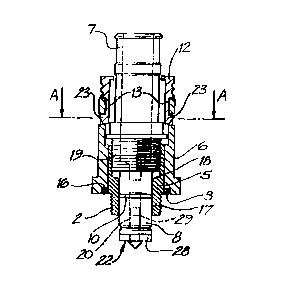
10152025W0 98/12460CA 02265627 1999-03-08PCTIAU97/00620-1-A RISING STEM TAP OF PLASTIC. PREFERABLY WITH A METAL THREADED INSERT' ld IThe present invention relates to taps and, in particular, to a tap body which isable to be fabricated from predominantly plastics material thereby substantiallyreducing the weight and cost of the tap relative to conventional taps.u f vConventional taps are fabricated from brass or similar non—corrosive materialand include a tap body having a threaded mounting spigot at one end and a stuffing boxat the other end. Suitably engaged, by means of a relatively course thread, with theinterior of the tap body is a tap spindle which is screwed into the tap body by passingthe shaft of the tap spindle through the mounting spigot and through the stuffing boxbefore engaging the threaded exterior of the tap spindle with the threaded interior of thetap body.After this installation has been completed, the stuffing box (which containscompressible material) is screwed further towards the tap body so as to compress thecompressible material against the shaft of the spindle. This provides the desiredwatertight seal between the interior of the tap body and the shaft of the spindle.The foregoing arrangement has been in use for many years and provides manyadvantages, particularly in terms of strength and durability. However, the arrangementsuffers from a number of disadvantages, the most important of which is that the stuffingbox begins to leak progressively over the years and if not re—tightened results in watermoving up the shaft of the tap spindle when the tap is open. This can lead tosignificant deterioration and corrosion of other components, for example mountingboards adjacent the sink into which the tap is positioned, and so on.In addition, as the cost of metal, brass in particular, increases, so the cost ofthe tap increases. If the tap body could be made predominantly of plastics material,then a substantial saving in both weight and cost could be achieved.10152025CA 02265627 1999-03-08W0 9'8/12460 PCT/AU97/00620-2-A search conducted after the priority date located US Patent No 4,493,338assigned to Waltec, Inc. of Canada and US Patent No 5,580,031 assigned to HansGrohe GmbH & Co. KG of Germany.Both of these documents disclose tap body assemblies comprising metalcomponents and suffer the disadvantages described above.The present invention is directed towards the above ends with a view tosubstantially reducing the above disadvantages and/or substantially achieving the aboveadvantages.S of I V n'In accordance with a first aspect of the present invention there is disclosed atap body comprising a first inner threaded portion, a plastics shroud surrounding. saidinner threaded portion, a substantially plastics tap spindle threadably received in saidfirst inner threaded portion and rotatably reciprocable in tap opening and tap closingdirections, and a locking collar engageable with said shroud to limit the tap openingrotation of said spindle.Preferably, the body has a smooth bore, and the spindle has a valve carrierincluding a sealing means which is adapted to slidably engage said bore to provide aseal between said spindle and body.rief llescrjptign of the DrawingsPreferred embodiment of the present invention will now be described withreference to the drawings in which:Fig. 1 is a perspective view of the assembled tap body of the first preferredembodiment;Fig. 2 is an exploded perspective view of the tap body of Fig. 1;Fig. 3 is a side elevational view of the tap body of Fig. 1;Fig. 4 is a longitudinal cross—section through the tap body of Fig. 3;Fig. 5 is a transverse cross-sectional view along the line A-A of Fig. 1;‘I52025W0 98/12460CA 02265627 1999-03-08PCTIAU97/00620Fig. 6 is a longitudinal cross—section through the assembled tap body of thesecond preferred embodiment;Fig. 7 is a longitudinal cross—section through the tap body and locking collar ofthe third preferred embodiment;Fig. 8 is a longitudinal cross—section through the tap body and locking collar ofthe fourth preferred embodiment; andFig. 9 is a longitudinal cross—section through the tap body, locking collar andtap shroud of the fifth preferred embodiment.D sc ' ' n f fe r dAs seen in Figs. 1 and 2 in particular, the first embodiment of the tap body 1has a threaded mounting spigot 2 which is of conventional size and thread configurationso as to permit the tap body 1 to be engaged with a conventional tap seat (notillustrated). As indicated in Fig. 2 a sealing O-ring 3 passes over the mounting spigot 2so as to provide a watertight seal between the tap body 1 and the tap seat (notillustrated).The mounting spigot 2 is itself part of a brass sleeve 5 (best seen in Fig. 4)which is positioned within a plastic shroud 6. A plastic spindle 7 is located within thetap body and has a valve carrier 8 at one (lower) end which has a groove 9 to receivean O-ring 10. The other end of the spindle 7 opposite the valve carrier 8 is ultimatelyconnected to the handle (not illustrated) of the tap. .A locking collar 12 having a pair of opposed legs 13,14 is snap—engageablewith the shroud 6 so as to limit the movement of the spindle 7 as will be explainedhereafter.As best seen in Fig. 4, the brass sleeve 5 is provided with a knurled exteriorand is placed into the mould prior to injection of the plastics from which the shroud 6 isformed. As a consequence, there is a good key between the brass of the sleeve 5 andthe plastics of the shroud 6. At the time of moulding the shroud 6 a groove 16 isformed which receives the sealing O—ring 3. It will also be apparent from Fig. 4 that10152025IllllCA 02265627 1999-03-08W0 98/12460 PCT/AU97/00620-4-the interior of the mounting spigot 2 has a smooth bore 17 which therefore provides agood seal together with the O-ring 10 thereby sealing the spindle 7 relative to thesleeve 5.In addition, the sleeve 5 has an interior threaded portion 18 which mates with acorresponding threaded portion 19 on the spindle 7. The inter-engagement of the twothreaded portions 18 and 19 permits the spindle 7 to be rotated within the valve body 1so as to move the valve carrier 8 relative to the mounting spigot 2. The valve carrier 8also includes a recess 20 for locating a conventional jumper valve 22 having a discshaped washer 28 and a stem 29 which is received in the recess 20.The spindle 7 can be inserted into the tap body 1 by means of passing thethreaded portion 19 through the top of the shroud 6 as indicated in Fig. 2. The spindle7 is then rotated in the tap closing direction so as to move the threaded portion 19towards the spigot 2. With the entire tap assembled, this tap closing movement of thespindle 7 is brought to an end because of engagement of the washer 28 of the jumpervalve 22 with the valve seat in the tap seat (not illustrated).However, in order to prevent rotation of the spindle 7 in the tap openingdirection inadvertently removing the tap spindle 7 from the shroud 6, the locking collar12 is provided. As best seen in Figs. 2 and 4, the legs 13 of the locking collar 12include cammed wedges 23 which snap engage into rectangular openings 25 in theshroud 6. An outer peripheral lip 27 on the spindle 7 engages with the distal ends ofthe legs 13 to limit the movement of the spindle 7 in the tap opening direction.As best seen in relation to Fig. 5, the locking collar 12 can be rotatedclockwise in order to deflect inwardly the legs 13 to thereby permit the locking collar12 to be withdrawn from the shroud 6 if the tap body 1 should be required to be dis-assembled.The above described arrangement provides a number of substantial advantages.Firstly, the tap body 1 is predominantly formed from lightweight and inexpensiveplastics material and therefore is of overall lightweight and low cost construction. The10152025CA 02265627 1999-03-08W0 93/11450 PCT/AU97/00620brass sleeve 5 provides for good dimensional tolerance for the bore 17 thereby ensuringa good seal between the shroud 6 and spindle 7. The tap body 1 is able to be retro-fitted to existing taps since the arrangement of the conventional jumper valve 22 and tapseat remain unchanged. The plastics tap spindle 7 is preferably provided with thetorque limiting clutch described in co—pending Australian Patent Application No.P 02416 (attorney reference 277596) the disclosure of which is hereby incorporatedherein by means of cross-reference. The main advantage of this arrangement is to limitthe torque which can be applied to the plastics spindle 7 via the handle (not illustrated).Fig. 6 shows a second embodiment of the tap body 30. Like referencenumerals to those used in describing the first embodiment denote like features in thesecond embodiment.In this second embodiment, the brass sleeve is omitted by moulding themounting spigot 2 integral with the plastics shroud 6. The smooth bore 17 and interiorthreaded portion 18 can be either moulded or machined into the shroud 6.Whilst, the first embodiment is best suited to installing plastic tapware ontoexisting brass plumbing fixtures, the second embodiment is best suited to plumbinginstallations using predominantly plastics fittings.Fig. 7 shows a third embodiment of the tap body 40 for use in three hole (tap,spout, tap) installations adjacent basins, baths and the like. Like numerals will again beused for like features.The tap body 40 includes a mains inlet 42 in fluid communication with a valveseat 44 which is opened and closed by the jumper valve (not shown) to selectivelycommunicate water to a tap outlet spigot 46. The outlet spigot 46 is connected to aspout T—piece (not shown).As with the second embodiment, the smooth bore 17 and interior threadedportion 18 are incorporated into the plastics shroud 6. The shroud 6 also includes anLocking nuts 50 engage the threaded portion 48 andexterior threaded portion 48.permit the tap body to be fastened to a basin surround 52 or the like.10CA 02265627 1999-03-08W0 98/12460 PCT/AU97l00620Fig. 8 shows a fourth embodiment of the tap body 60 in which the snap-engaging locking collar 12 is replaced by an externally threaded locking collar 62which engages a second interior threaded portion 64 provided on the tap end of theshroud 6. The collar 62 has an inner peripheral lip 64 which engages the outerperipheral lip 27 on the spindle 7 to limit the movement of the spindle 7 in the tapopening direction.Fig. 9 shows a fifth embodiment of the tap body 70 with a modified threadedlocking collar 72 including a threaded spigot 74 for engagement with the interiorthreaded portion 76 of tap shroud 78.The foregoing describes only five embodiments of the present invention andmodifications, obvious to those skilled in the art, can be made thereto without departingfrom the scope of the present invention.
Representative Drawing
A single figure which represents the drawing illustrating the invention.
Administrative Status

2024-08-01:As part of the Next Generation Patents (NGP) transition, the Canadian Patents Database (CPD) now contains a more detailed Event History, which replicates the Event Log of our new back-office solution.

Please note that "Inactive:" events refers to events no longer in use in our new back-office solution.

For a clearer understanding of the status of the application/patent presented on this page, the site Disclaimer , as well as the definitions for Patent , Event History , Maintenance Fee  and Payment History  should be consulted.

Event History

Description Date
Inactive: Adhoc Request Documented 2018-06-06
Appointment of Agent Requirements Determined Compliant 2018-05-18
Revocation of Agent Requirements Determined Compliant 2018-05-18
Inactive: IPC from MCD 2006-03-12
Application Not Reinstated by Deadline 2002-09-19
Time Limit for Reversal Expired 2002-09-19
Deemed Abandoned - Failure to Respond to Maintenance Fee Notice 2001-09-19
Inactive: Office letter 2000-04-10
Inactive: Correspondence - Transfer 2000-02-21
Letter Sent 1999-06-01
Inactive: Cover page published 1999-05-19
Inactive: IPC assigned 1999-05-03
Inactive: First IPC assigned 1999-05-03
Inactive: IPC assigned 1999-05-03
Inactive: Single transfer 1999-04-28
Inactive: Courtesy letter - Evidence 1999-04-27
Inactive: Notice - National entry - No RFE 1999-04-20
Inactive: Applicant deleted 1999-04-20
Inactive: Applicant deleted 1999-04-19
Application Received - PCT 1999-04-16
Application Published (Open to Public Inspection) 1998-03-26

Abandonment History

Abandonment Date Reason Reinstatement Date
2001-09-19

Maintenance Fee

The last payment was received on 2000-09-13

Note : If the full payment has not been received on or before the date indicated, a further fee may be required which may be one of the following

  • the reinstatement fee;
  • the late payment fee; or
  • additional fee to reverse deemed expiry.

Please refer to the CIPO Patent Fees web page to see all current fee amounts.

Fee History

Fee Type Anniversary Year Due Date Paid Date
Basic national fee - standard 1999-03-08
Registration of a document 1999-04-28
MF (application, 2nd anniv.) - standard 02 1999-09-20 1999-08-23
MF (application, 3rd anniv.) - standard 03 2000-09-19 2000-09-13
Owners on Record

Note: Records showing the ownership history in alphabetical order.

Current Owners on Record
CAROMA INDUSTRIES LIMITED
Past Owners on Record
JOHN JOSEPH EAGLE
Past Owners that do not appear in the "Owners on Record" listing will appear in other documentation within the application.
Documents

To view selected files, please enter reCAPTCHA code :


To view images, click a link in the Document Description column. To download the documents, select one or more checkboxes in the first column and then click the "Download Selected in PDF format (Zip Archive)" or the "Download Selected as Single PDF" button.

List of published and non-published patent-specific documents on the CPD .

If you have any difficulty accessing content, you can call the Client Service Centre at 1-866-997-1936 or send them an e-mail at CIPO Client Service Centre.


Document
Description 
Date
(yyyy-mm-dd) 
Number of pages   Size of Image (KB) 
Representative drawing 1999-05-18 1 8
Description 1999-03-08 6 255
Claims 1999-03-08 3 101
Drawings 1999-03-08 6 122
Abstract 1999-03-08 1 55
Cover Page 1999-05-18 1 48
Notice of National Entry 1999-04-20 1 193
Reminder of maintenance fee due 1999-05-20 1 112
Courtesy - Certificate of registration (related document(s)) 1999-06-01 1 116
Courtesy - Abandonment Letter (Maintenance Fee) 2001-10-17 1 185
Reminder - Request for Examination 2002-05-22 1 118
PCT 1999-03-08 7 312
Correspondence 1999-04-27 1 30
Correspondence 2000-04-10 1 7
Fees 1999-08-23 1 32
Fees 2000-09-13 1 35