Language selection

Search

Patent 2266187 Summary

Third-party information liability

Some of the information on this Web page has been provided by external sources. The Government of Canada is not responsible for the accuracy, reliability or currency of the information supplied by external sources. Users wishing to rely upon this information should consult directly with the source of the information. Content provided by external sources is not subject to official languages, privacy and accessibility requirements.

Claims and Abstract availability

Any discrepancies in the text and image of the Claims and Abstract are due to differing posting times. Text of the Claims and Abstract are posted:

  • At the time the application is open to public inspection;
  • At the time of issue of the patent (grant).
(12) Patent Application: (11) CA 2266187
(54) English Title: MOVE-IN-COMPANY STYLE JOY STICK
(54) French Title: MANETTE DE JEU A DISPOSITIF MOBILE
Status: Deemed Abandoned and Beyond the Period of Reinstatement - Pending Response to Notice of Disregarded Communication
Bibliographic Data
(51) International Patent Classification (IPC):
  • G05G 09/047 (2006.01)
  • A63F 13/24 (2014.01)
  • G06F 03/033 (2013.01)
(72) Inventors :
  • CHEN, LILY (Taiwan, Province of China)
(73) Owners :
  • LILY CHEN
(71) Applicants :
  • LILY CHEN (Taiwan, Province of China)
(74) Agent: MARKS & CLERK
(74) Associate agent:
(45) Issued:
(22) Filed Date: 1999-03-19
(41) Open to Public Inspection: 2000-09-19
Availability of licence: N/A
Dedicated to the Public: N/A
(25) Language of filing: English

Patent Cooperation Treaty (PCT): No

(30) Application Priority Data: None

Abstracts

English Abstract


A move-in-company style joy stick comprising in a knob
thereof a space of suitable size formed by a partition
plate, a ball added with a weight, a horizontal grating and
a vertical grating are placed in the space. The horizontal
and vertical gratings are provided each with a coaxial
roller respectively contact the ball in rotation at a
position slightly lower than a horizontal central line of
the ball. A supporting wheel is provided at a position
having an equal angular distance to both the coaxial
rollers. When the knob of the joy stick is shaken, a
vertical central line of the ball added with the weight is
always kept in its vertical position, hence the coaxial
rollers are rubbed by the ball in rotation. In this way,
the required amount of displacement of the horizontal and
vertical gratings being shaken is obtained.


Claims

Note: Claims are shown in the official language in which they were submitted.

The embodiments of the invention in which an exclusive
property or privilege is claimed are defined as follows:
1. A move-in-company style joy stick, comprising in a
knob thereof a space formed by a partition plate, a ball
added with a weight, a horizontal grating and a vertical
grating are placed in said space, said gratings are provided
each with a coaxial roller respectively contact said ball in
rotation at a position slightly lower than a horizontal
central line of said ball, a supporting wheel is provided at
a position having an equal angular distance to both said
coaxial rollers;
when said knob of said joy stick is shaken, a vertical
central line of said ball added with said weight is always
kept in its vertical position, hence said coaxial rollers are
rubbed by said ball in rotation, in this way, the required
amount of displacement of said horizontal and vertical
grating being shaken is obtained.
2. A move-in-company style joy stick as in claim 1,
wherein, said ball added with said weight is provided near
the bottom thereof with a central through hole, above a
bottom surface of said central through hole, there is said
weight of which the position is preferably lower than a
horizontal central line of said roller.
3. A move-in-company style joy stick as in claim 2,
wherein, said central through hole is provided on the top
thereof with a filler block above which a releasing-proof
device is provided on the top of said knob of said joy stick.
4. A move-in-company style joy stick as in claim 3,
wherein, said releasing-proof device is provided on the top
of said knob of said joy stick with a cylinder which is
integrally connected with said knob and has a spring therein,
an exposed small ball is provided in front of said spring.

Description

Note: Descriptions are shown in the official language in which they were submitted.


CA 02266187 1999-08-03
TITLE: MOVE-IN-COMPANY STYLE JOY STICK
BACKGROUND OF THE INVENTION
1. Field of the Invention
The present invention is related to a move-in-company
style joy stick, and especially to a move-in-company style
joy stick of which internal elements move in company
therewith and thereby amount of displacement in operation
can be detected. In this way, the whole joy stick can get
rid of limitation of the bottom receiving-seat.
2. Description of the Prior Art
A conventional joy stick used for a computer or a
television game device mostly is provided at the central
position of a bottom receiving-seat. By shaking of the joy
stick, internal gratings in the bottom receiving-seat move
relatively, in this way, the required amount of
displacement in operation can be obtained. However, the
joy stick must be combined in operation with the bottom
receiving-seat, this makes much inconvenience. In order to
2o make clear of the structure and functions of the
conventional joy stick, Fig. 1 is taken as a reference for
explanation:
A conventional joy stick has a control rod 10 with a
suitable length for holding by a user, the control rod 10
is provided near the central position of a bottom
receiving-seat 11. The bottom receiving-seat 11 is
provided internally thereof with a horizontal grating 12
and a vertical grating 13 connected operationally with the
control rod 10. The horizontal grating 12 and the vertical
3o grating 13 are mounted respectively in a detecting device
14 and a detecting device 15. When the user moves the
1

CA 02266187 1999-08-03
control rod 10, the end 16 of the control rod 10 moves
synchronically the gratings 12 and 13, the detecting
devices 14, 15 can thereby detect the required amount of
displacement in operation. And the joy stick can get the
control function.
The main defect of such a conventional joy stick is
that the control rod 10 for moving must be connected to the
bottom receiving-seat 11 with a specified size. In order
to prevent from instability induced by shaking and moving
l0 of the whole joy stick when force is applied in using, the
bottom receiving-seat 11 must have quite a large bottom
area. This makes the necessity of a larger volume of the
bottom receiving-seat 11. And if the user wants to control
the joy stick at a farther distance or in a more
comfortable posture, the control rod 10 shall be moved
together with the bottom receiving-seat 11 as a whole,
inconvenience results in such operation.
SUMMARY OF THE INVENTION
2o The main object of the present invention is to provide
a move-in-company style joy stick, wherein, the knob of the
move-in-company style joy stick is provided internally with
a ball with a suitable size. The ball is added with a
weight at the lower portion thereof. A horizontal grating
and a vertical grating are provided therein and are
provided respectively with a coaxial roller; these rollers
contact the ball at the levels slightly lower than the
horizontal central line of the ball. The ball with the
added weight rubs the rollers in rotation when the joy
3o stick is moved, thereby, the required amount of
displacement in operation can be obtained: In this way,
2

CA 02266187 1999-08-03
the whole joy stick itself is able of detect the required
amount of displacement thereof. It can therefore operate
independently and is out of limitation of requiring a
bottom receiving-seat of large volume.
The present invention will be apparent in the novelty
and other features thereof after reading the detailed
description of the preferred embodiment thereof in
reference to the accompanying drawings.
BRIEF DESCRIPTION OF THE DRAWINGS
In the drawings:
Fig. 1 is a schematic view showing the motion in a
conventional joy stick;
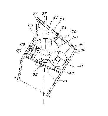
Fig. 2 is a sectional view showing the state of
shaking of an embodiment of the present invention;
Fig. 3 is a side view showing the internal mechanism
of the embodiment of Fig. 2;
Fig. 4 is a top view showing the internal mechanism of
the embodiment of Fig. 2;
2o Fig. 5 is a perspective sectional view showing a
weight added to the present invention;
Fig. 6 is a schematic view showing clockwise motion of
the embodiment of Fig. 3;
Fig. 7 is a schematic view showing counterclockwise
motion of the embodiment of Fig. 3.
DETAILED DESCRIPTION OF THE PREFERRED EMBODIMENT
Referring to Fig. 2, a hollow knob 20 of the joy stick
of the present invention is provided therein with a space
30 of suitable size formed by a partition plate 21 for
mounting therein a ball 30 added with a weight, and for
3

CA 02266187 1999-08-03
mounting therein a horizontal grating 40, a verticalY
grating 50, a supporting wheel 60 and a releasing-proof
device 70.
Referring together to Fig. 3 and 4, the horizontal
grating 40 and the vertical grating 50 are provided with a
coaxial roller 41 and a coaxial roller 51 respectively
contacting the ball 30. The ball 30 shown in Fig. 3 is
drawn with a horizontal central line 300, while a
horizontal central line c of the coaxial roller 41 and of
1o the coaxial roller 51 is preferably at the position a
distance "a" slightly lower than the horizontal central
line 300. The supporting wheel 60 is preferably provided
at a position having an equal angular distance to both the
coaxial roller 41 and the coaxial roller 51, and is also on
the horizontal central line c of the coaxial roller 41 and
the coaxial roller 51. A support 42 and a support 52
respectively of the coaxial roller 41 and the coaxial
roller 51 as well as a support 62 of the supporting wheel
60 are all provided on the partition plate 21.
20 As shown in Fig. 3, 5, in the preferred embodiment of
the present invention depicted therein, the ball 30 added
with a weight is provided near the bottom thereof with a
central through hole 31. Above a bottom surface 33 of the
central through hole 31, there is the weight 35 of which
the position is preferably lower than the horizontal
central line c.
Referring together to Fig. 2, 6 and 7, with the above
stated structure of joy stick, no matter how the knob 20 of
the joy stick moves, the ball 30 provided therein added
30 with the weight 35 has a vertical central line 303 thereof
always kept in its vertical position. While the coaxial
4

CA 02266187 1999-08-03
roller 41 and the coaxial roller 51 displace in pursuance
of moving of the knob 20 of the joy stick and are rubbed by
the ball 30 in rotation. In this way, the horizontal
grating 40 and the vertical grating 50 both are shaken to
obtain the required amount of displacement. Thereby,
moving or shaking of the joy stick can allow detection of
the amount of displacement.
In order to get larger stability in operation of the
whole joy stick, the central through hole 31 of the ball 30
is provided on the top thereof with a filler block 37 which
is pressed by the releasing-proof device 70. In
cooperation with this filler block 37, the releasing-proof
device 70 is provided on the top of and integrally with the
knob 20 of the joy stick with a cylinder 71 which has a
spring 72 therein. An exposed small ball 73 is provided in
front of the spring 72 for pressing the filler block 37.
By the fact that the present invention can obtain the
required amount of displacement during movement of itself,
the joy stick needs only a very small bottom receiving-seat
2o for electric connection. There is no more requirement of a
bottom receiving-seat with a large volume; this can largely
reduce the volume in manufacturing as well as in packaging.
Besides, without limitation of requiring a bottom
receiving-seat with a large volume, a user can operate the
joy stick in any comfortable posture.
Having thus described my invention, what I claim as
new and desire to be secured by Letters Patent of the
United States are:
5

Representative Drawing
A single figure which represents the drawing illustrating the invention.
Administrative Status

2024-08-01:As part of the Next Generation Patents (NGP) transition, the Canadian Patents Database (CPD) now contains a more detailed Event History, which replicates the Event Log of our new back-office solution.

Please note that "Inactive:" events refers to events no longer in use in our new back-office solution.

For a clearer understanding of the status of the application/patent presented on this page, the site Disclaimer , as well as the definitions for Patent , Event History , Maintenance Fee  and Payment History  should be consulted.

Event History

Description Date
Inactive: IPC deactivated 2014-05-17
Inactive: IPC from PCS 2014-02-01
Inactive: IPC expired 2014-01-01
Inactive: IPC assigned 2013-02-04
Inactive: IPC deactivated 2011-07-29
Inactive: First IPC derived 2006-03-12
Inactive: IPC from MCD 2006-03-12
Time Limit for Reversal Expired 2004-03-19
Application Not Reinstated by Deadline 2004-03-19
Deemed Abandoned - Failure to Respond to Maintenance Fee Notice 2003-03-19
Inactive: Entity size changed 2002-03-26
Inactive: Cover page published 2000-09-21
Application Published (Open to Public Inspection) 2000-09-19
Inactive: Correspondence - Formalities 1999-08-03
Inactive: IPC assigned 1999-05-06
Inactive: First IPC assigned 1999-05-06
Inactive: Filing certificate - No RFE (English) 1999-04-22
Application Received - Regular National 1999-04-21

Abandonment History

Abandonment Date Reason Reinstatement Date
2003-03-19

Maintenance Fee

The last payment was received on 2002-03-18

Note : If the full payment has not been received on or before the date indicated, a further fee may be required which may be one of the following

  • the reinstatement fee;
  • the late payment fee; or
  • additional fee to reverse deemed expiry.

Patent fees are adjusted on the 1st of January every year. The amounts above are the current amounts if received by December 31 of the current year.
Please refer to the CIPO Patent Fees web page to see all current fee amounts.

Fee History

Fee Type Anniversary Year Due Date Paid Date
Application fee - small 1999-03-19
MF (application, 2nd anniv.) - small 02 2001-03-19 2001-03-12
MF (application, 3rd anniv.) - standard 03 2002-03-19 2002-03-18
Owners on Record

Note: Records showing the ownership history in alphabetical order.

Current Owners on Record
LILY CHEN
Past Owners on Record
None
Past Owners that do not appear in the "Owners on Record" listing will appear in other documentation within the application.
Documents

To view selected files, please enter reCAPTCHA code :


To view images, click a link in the Document Description column (Temporarily unavailable). To download the documents, select one or more checkboxes in the first column and then click the "Download Selected in PDF format (Zip Archive)" or the "Download Selected as Single PDF" button.

List of published and non-published patent-specific documents on the CPD .

If you have any difficulty accessing content, you can call the Client Service Centre at 1-866-997-1936 or send them an e-mail at CIPO Client Service Centre.

({010=All Documents, 020=As Filed, 030=As Open to Public Inspection, 040=At Issuance, 050=Examination, 060=Incoming Correspondence, 070=Miscellaneous, 080=Outgoing Correspondence, 090=Payment})


Document
Description 
Date
(yyyy-mm-dd) 
Number of pages   Size of Image (KB) 
Representative drawing 2000-09-20 1 11
Description 1999-03-18 5 185
Claims 1999-03-18 1 37
Drawings 1999-03-18 5 79
Abstract 1999-08-02 1 23
Claims 1999-08-02 1 44
Description 1999-08-02 5 202
Drawings 1999-08-02 5 85
Abstract 1999-03-18 1 21
Filing Certificate (English) 1999-04-21 1 164
Reminder of maintenance fee due 2000-11-20 1 112
Courtesy - Abandonment Letter (Maintenance Fee) 2003-04-15 1 176
Reminder - Request for Examination 2003-11-19 1 123
Correspondence 1999-04-26 1 24
Correspondence 1999-08-02 13 379