Language selection

Search

Patent 2266231 Summary

Third-party information liability

Some of the information on this Web page has been provided by external sources. The Government of Canada is not responsible for the accuracy, reliability or currency of the information supplied by external sources. Users wishing to rely upon this information should consult directly with the source of the information. Content provided by external sources is not subject to official languages, privacy and accessibility requirements.

Claims and Abstract availability

Any discrepancies in the text and image of the Claims and Abstract are due to differing posting times. Text of the Claims and Abstract are posted:

  • At the time the application is open to public inspection;
  • At the time of issue of the patent (grant).
(12) Patent Application: (11) CA 2266231
(54) English Title: GYNAECOLOGICAL SAMPLERS
(54) French Title: APPAREILS DE PRELEVEMENTS GYNECOLOGIQUES
Status: Deemed Abandoned and Beyond the Period of Reinstatement - Pending Response to Notice of Disregarded Communication
Bibliographic Data
(51) International Patent Classification (IPC):
  • A61B 10/00 (2006.01)
(72) Inventors :
  • RIDOUT, PAUL BENJAMIN (United Kingdom)
  • MORRIS, EDWARD PATRICK (United Kingdom)
(73) Owners :
  • EDWARD PATRICK MORRIS
  • SMITHS GROUP PLC
(71) Applicants :
  • EDWARD PATRICK MORRIS (United Kingdom)
  • SMITHS GROUP PLC (United Kingdom)
(74) Agent: SMART & BIGGAR LP
(74) Associate agent:
(45) Issued:
(22) Filed Date: 1999-03-19
(41) Open to Public Inspection: 1999-10-01
Availability of licence: N/A
Dedicated to the Public: N/A
(25) Language of filing: English

Patent Cooperation Treaty (PCT): No

(30) Application Priority Data:
Application No. Country/Territory Date
9807075 (United Kingdom) 1998-04-01

Abstracts

English Abstract


Known endometrial samplers has an outer catheter and an inner plunger slidable
within the catheter. The catheter has a single circular side opening close to
its tip through
which samples are aspirated into the catheter. In the present invention the
catheter has two
two side openings located diametrically opposite one another close to the tip,
the side
openings being elongate along the axis of the catheter. The catheter also has
a coaxial
opening at its tip. The tip of the plunger projects into the tip opening to
form a smooth
surface to the sampler. An O-ring seal on the plunger is located rearwardly of
the side
openings so that suction is applied to both the side openings and the tip
opening when the
plunger is pulled rearwardly.


Claims

Note: Claims are shown in the official language in which they were submitted.

7
THE EMBODIMENT OF THE INVENTION IN WHICH AN EXCLUSIVE PROPERTY
OR PRIVILEGE IS CLAIMED ARE DEFINED AS FOLLOWS:
1. A gynecological sampler comprising: an outer catheter, said outer catheter
having a
forward end and a rear end, a cylindrical wall, at least one side opening in
said
cylindrical wall towards said forward end, and at least one further opening in
said
catheter towards said forward end; and a plunger with a forward end and a rear
end,
said plunger being slidable from a first forward position to a second rear
position so
that suction is applied to draw material into said catheter through said
openings.
2. A sampler according to Claim 1, wherein said further opening is a second
side
opening in said cylindrical wall.
3. A sampler according to Claim 2, wherein the two said side openings are
located
diametrically opposite one another.
4. A sampler according to Claim 1, wherein said side opening is elongate along
an axis
of said catheter.
5. A sampler according to Claim 1, wherein said catheter has an opening at its
forward
end located coaxially of said catheter.
6. A sampler according to Claim 5, wherein said plunger projects into said
coaxial
opening forming a smooth tip to the sampler.

8
7. A sampler according to Claim 1, wherein said plunger has an O-ring seal,
and wherein
said O-ring seal is located to the rear of said side opening when said plunger
is in said
first position.
8. An endometrial sampler comprising: an outer catheter, said outer catheter
having a
forward end, a rear end, a cylindrical wall, and two elongate side openings
diametrically opposite one another in said cylindrical wall towards said
forward end;
and a plunger with a forward end and a rear end, said plunger being slidable
from a
first forward position to a second rear position so that suction is applied to
draw
endometrial material into said catheter through said openings.
9. An endometrial sampler according to Claim 8, wherein said catheter includes
a third
opening located coaxially at said forward end of said catheter, and wherein
said
plunger extends into said third opening when said plunger is in its first
position.
10. An endometrial sampler comprising: an outer catheter, said outer catheter
having a
forward end, a rear end, a cylindrical wall, two side openings in said
cylindrical wall
towards said forward end. and a third coaxial-opening at the tip of the
catheter; and a
plunger with a forward end, a rear end, and a seal located between said
forward and
rear ends of said plunger, wherein said plunger is slidable from a first
position in
which said forward end closes said third opening and said seal seals with said
catheter
to the rear of said two side openings to a second position in which said
forward end of
said plunger is located rearwardly of all three openings and endometrial
material is
drawn into said catheter through said openings.

Description

Note: Descriptions are shown in the official language in which they were submitted.


CA 02266231 1999-03-19
GYNAECOLOGICAL SAMPLERS
Background of the Invention
This invention relates to gynaecological samplers.
Gynaecological samplers are used to take samples from the uterus, cervix or
the like,
such as endometrial cells lining the uterus. The sampler usually comprises a
plastic catheter
and a plunger device movable within the catheter. The tip of the catheter is
closed and cells
are admitted via a single, circular side opening close to the tip when suction
is applied by
pulling back on the plunger. The problem with such samplers is that it can be
difficult to
obtain large numbers of cells. Examples of gynaecological samplers are
described in, for
example: FR 2602414, WO 97/19642, US 4534362, GB 2126100, US 5069225, US
5807282,
US 5464022, US 4877037, US4662381, US4396022, US 4340066 and "The Pipelle: A
disposable device for endometrial biopsy" by E Cornier, Am. J. Obstet.
Gynecol. Jan 1, 1984,
pp109-110.
Brief Summary of the Invention
It is an object of the present invention to provide an improved gynaecological
sampler.
According to the present invention there is provided a gynaecological sampler
having
an outer catheter and an inner plunger, the outer catheter having a
cylindrical wall with at
least one side opening towards its patient end, the catheter having at least
one further opening
towards its patient end, and the plunger being slidable from a first forward
position to a

CA 02266231 1999-03-19
2
second rear position so that suction is applied to draw material into the
catheter through the
openings.
Preferably, the catheter has two side openings in the cylindrical wall of the
catheter,
such as located diametrically opposite one another, and the side openings are
preferably
elongate along the axis of the catheter. Preferably the catheter also has an
opening at its tip
located coaxially of the catheter. The plunger preferably proj ects into the
opening at the tip of
the catheter so as to form a smooth tip to the sampler. The plunger may have
an O-ring seal,
the O-ring seal being located to the rear of the or each side opening when the
plunger is fully
inserted in the catheter.
An endometrial sampler according to the present invention, will now be
described, by
way of example, with reference to the accompanying drawings.
Brief Description of the Drawings
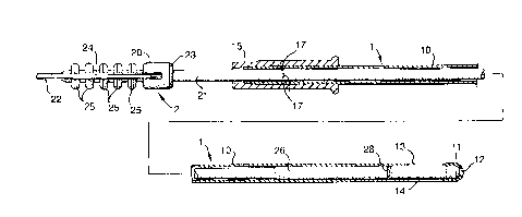
Figure 1 is a plan view of the sampler;
Figure 2 is a cross-sectional side elevation view of the sampler;
Figure 3 is a cross-sectional side elevation view of the tip of the sampler
to an enlarged scale; and

CA 02266231 1999-03-19
3
Figure 4 is a side elevation view of the tip of the plunger to an enlarged
scale.
Detailed Descr~tion of the Preferred Embodiment
The sampler comprises an outer catheter 1 and a plunger 2 that is slidable
axially
within the catheter.
The catheter 1 is typically about 250mm long and has tubular shaft 10 of
cylindrical
shape with an outer diameter of about 3mm and an inner diameter of about
2.4mm. The shaft
is extruded from a flexible plastics material such as polypropylene and is end
formed at its
forward, patient end 11 to give it a rounded tip with a coaxial opening 12 of
circular shape
having a diameter about half the external diameter of the shaft. The shaft 10
is also formed
with two further openings close to the forward, patient end tip in the form of
side openings 13
and 14. The side openings 13 and 14 are located diametrically opposite one
another set back
rearwardly from the tip 11 by a distance of about 4mm in a cylindrical region
of the shaft 10.
Each opening 13 and 14 is elongated axially, being about 2mm wide and 4mm long
with
rounded ends. The catheter 1 also includes a collar 15 at its rear or machine
end 16 into
which the rear end of the shaft 10 is fixed. The collar 15 has five internal
pips 17 about half
way along its length, which help constrict and grip the outside of the shaft
10. The collar 15
has an external annular rib 18 at its forward end and several longitudinal
ribs 19, which help
provide a secure grip when held between the finger and thumb. A small
clearance between
the outside of the plunger 2 and the rear end of the shaft 10 allows trapped
air to be expelled
from the catheter as the plunger is pulled rearwardly. The shaft 10 of the
catheter is
preferably marked with distance markings (not shown) from its tip.

CA 02266231 1999-03-19
4
i r
The plunger 2 also acts as a stylet to stiffen the catheter 1 during
insertion. The
plunger 2 is longer than the catheter l, being typically about 313mm long and
comprises a
rear handle 20 and a rod 21 extending forwardly from the handle. The plunger
is made from a
relatively stiff but bendable material such as polypropylene or nylon. The
handle 20 is about
23mm long and comprises a flat plate 22 with a cylindrical boss 23 at its
forward end. The
handle has gripping projections on its upper and lower surface provided by an
axial spine 24
and five lateral ribs 25 on each surface. The rod 21 is solid, being 290mm
long and of circular
section with a diameter of 2mm along most of its length. The diameter of the
rod 21 is
increased slightly to 2.2mm along a region 26 extending forwardly from a
location 32mm
from the tip of the rod. An annular groove 27, with a curved profile, is
formed around the rod
21 in the region 26 at a location about l2.Smm from the tip. The groove 27
serves to retain an
O-ring seal 28. The diameter of the rod 21 is further increased to 2.35mm
along a region 29,
which is about 1.Smm long. This enlarged region 29 adjoins a short tapered
region 30, about
O.Smm long. The tapered region 30 adjoins a nose portion 31 comprising a rear
cylindrical
portion 32 and a forward domed portion 33, the diameter of the rear portion
being l.4mm.
When the plunger 2 is located in the catheter -1 in its fully forward
position, the nose
portion 31 proj ects into the tip opening 12 of the catheter as a close fit
and with the domed
portion 3 3 of the rod 21 forming a smooth continuation of the rounded tip 11
of the catheter
and closing the opening. Because the plunger 2 extends to the tip of the
catheter l, it acts to
stiffen it along its entire length and, in particular, it stiffens it in the
region of the openings
12, 13 and 14. The enlarged portion 29 of the rod 21 is a close sliding fit
within the catheter
l and is located forwardly of the side openings 13 and 14. The region 26,
being slightly

CA 02266231 1999-03-19
smaller in diameter, allows a small clearance between its outside and the
inside of the
a=
catheter 1 but the O-ring seal 28 provides an effective, fluid-tight sliding
seal with the inside
of the catheter at a location to the rear of the side openings 13 and 14
thereby closing the side
openings.
The sampler is used by inserting its forward end 11 into the uterus with the
plunger 2
pushed fully forwardly in the catheter 1. The next step is for the user to
withdraw the plunger
2, whilst leaving the tip 11 of the catheter 1 in substantially the same
position. As the plunger
2 is withdrawn, it opens the openings 12, 13 and 14 and applies a suction
force to them. The
plunger 2 is withdrawn to its full extent, as limited by engagement of the
enlarged portion 26
with the constriction in the catheter 1 caused by the pips 17 in the collar
15. Engagement with
the surrounding tissue limits the rate at which fluid and cells in the
vicinity to be sucked into
the catheter 1. The patient tip 11 of the sampler is then rotated and rubbed
gently backwards
and forwards a few times against the endometrium lining the uterus to free
endometrial cells.
It has been found that the elongated shape of the side openings 13 and 14
significantly
increases the effectiveness in loosening of these cells because the longer
perimeter of each
opening compared with a conventional circular opening causes an abrasive
action over a
wider area. Also, the use of two openings 13 and 14 on opposite sides further
enhances the
liberation of cells. The rounded tip 11 of the sampler will also cause
detachment of some
cells. The suction force applied by withdrawing the plunger 2 sucks the
loosened cells into
the catheter during this rubbing action.
The construction of the sampler has several advantages. In addition to
providing an
increased liberation of cells, the different orientation of the three openings
helps ensure

CA 02266231 1999-03-19
6
collection of cells from all around the tip of the sampler, leading to an
increased number of
collected cells. Another advantage is that the large area side eyes enable the
sample to be
expelled more easily than in previous samplers where it was often necessary to
cut off the tip
of the sampler before expelling the sample. Also, the elongated shape of the
side openings
gives them a greater cross-section and helps reduce damage to the cells that
might otherwise
be caused by passage into and out of the sampler through a constricted
opening.

Representative Drawing
A single figure which represents the drawing illustrating the invention.
Administrative Status

2024-08-01:As part of the Next Generation Patents (NGP) transition, the Canadian Patents Database (CPD) now contains a more detailed Event History, which replicates the Event Log of our new back-office solution.

Please note that "Inactive:" events refers to events no longer in use in our new back-office solution.

For a clearer understanding of the status of the application/patent presented on this page, the site Disclaimer , as well as the definitions for Patent , Event History , Maintenance Fee  and Payment History  should be consulted.

Event History

Description Date
Time Limit for Reversal Expired 2005-03-21
Application Not Reinstated by Deadline 2005-03-21
Inactive: Abandon-RFE+Late fee unpaid-Correspondence sent 2004-03-19
Deemed Abandoned - Failure to Respond to Maintenance Fee Notice 2004-03-19
Letter Sent 2001-08-09
Application Published (Open to Public Inspection) 1999-10-01
Inactive: Cover page published 1999-09-30
Letter Sent 1999-06-01
Inactive: Correspondence - Transfer 1999-05-12
Inactive: First IPC assigned 1999-05-07
Inactive: IPC assigned 1999-05-07
Inactive: Courtesy letter - Evidence 1999-04-27
Application Received - Regular National 1999-04-22
Filing Requirements Determined Compliant 1999-04-22
Inactive: Filing certificate - No RFE (English) 1999-04-22
Inactive: Single transfer 1999-04-16

Abandonment History

Abandonment Date Reason Reinstatement Date
2004-03-19

Maintenance Fee

The last payment was received on 2003-02-26

Note : If the full payment has not been received on or before the date indicated, a further fee may be required which may be one of the following

  • the reinstatement fee;
  • the late payment fee; or
  • additional fee to reverse deemed expiry.

Please refer to the CIPO Patent Fees web page to see all current fee amounts.

Fee History

Fee Type Anniversary Year Due Date Paid Date
Application fee - standard 1999-03-19
Registration of a document 1999-04-16
MF (application, 2nd anniv.) - standard 02 2001-03-19 2001-02-09
MF (application, 3rd anniv.) - standard 03 2002-03-19 2002-02-15
MF (application, 4th anniv.) - standard 04 2003-03-19 2003-02-26
Owners on Record

Note: Records showing the ownership history in alphabetical order.

Current Owners on Record
EDWARD PATRICK MORRIS
SMITHS GROUP PLC
Past Owners on Record
PAUL BENJAMIN RIDOUT
Past Owners that do not appear in the "Owners on Record" listing will appear in other documentation within the application.
Documents

To view selected files, please enter reCAPTCHA code :


To view images, click a link in the Document Description column. To download the documents, select one or more checkboxes in the first column and then click the "Download Selected in PDF format (Zip Archive)" or the "Download Selected as Single PDF" button.

List of published and non-published patent-specific documents on the CPD .

If you have any difficulty accessing content, you can call the Client Service Centre at 1-866-997-1936 or send them an e-mail at CIPO Client Service Centre.


Document
Description 
Date
(yyyy-mm-dd) 
Number of pages   Size of Image (KB) 
Representative drawing 1999-09-23 1 7
Abstract 1999-03-19 1 20
Description 1999-03-19 6 208
Claims 1999-03-19 2 70
Drawings 1999-03-19 2 47
Cover Page 1999-09-23 1 36
Filing Certificate (English) 1999-04-22 1 165
Courtesy - Certificate of registration (related document(s)) 1999-06-01 1 116
Reminder of maintenance fee due 2000-11-21 1 112
Reminder - Request for Examination 2003-11-20 1 123
Courtesy - Abandonment Letter (Request for Examination) 2004-05-31 1 167
Courtesy - Abandonment Letter (Maintenance Fee) 2004-05-17 1 175
Correspondence 1999-04-27 1 30