Note: Descriptions are shown in the official language in which they were submitted.
CA 02266287 1999-03-23
-1-
DISPOSABLE DIAPER
This invention relates to a disposable diaper having
barrier cuffs and the like.
Japanese Patent Publication No. Hei3-80502 discloses a
disposable diaper comprising a liquid-pervious topsheet, a
liquid-impervious backsheet, a liquid-absorbent core disposed
between these two sheets and a pair of barrier cuffs in the
form of flexible flaps adapted to be stretched and contracted
under effect of elastic members. Each of the barrier cuffs
comprises a branch section extending upwards from an inner
surface of the diaper, and a sealing surface zone consisting
of a first overhead section extending inwards from the branch
section and a second overhead section extending outwards from
the branch section. The elastic members are provided in the
seal surface zone. With the diaper of such a well known
arrangement, it can be principally expected that the first
overhead section elastically fits around the wearer's thigh
and thereby forms an inwardly opening pocket to receive loose
passage or urine. The second overhead section also
elastically fits around the wearer's thigh and improves a
preventive effect against leakage of excretion.
CA 02266287 1999-03-23
-2-
For the well known diaper as has been described, it is
desired that the first and second overhead sections can be
laterally developed without being folded one upon another and
come in contact with the wearer' s thigh over an area as large
as possible. In view of this demand, it is an object of the
invention to improve the known diaper so that the first and
second overhead sections can be reliably developed and
brought in contact with the wearer's thigh in the desired
manner.
According to the invention, there is provided a
disposable diaper having a front waist region, a rear waist
region and a crotch region therebetween, the diaper including
a liquid-pervious topsheet, a liquid-impervious backsheet and
a liquid-absorbent core disposed therebetween, and further
including a pair of flexible barrier cuffs extending in a
longitudinal direction along the crotch region into the front
and rear waist regions and adapted to be elastically
stretched/contracted in the direction under effect of a
plurality of elastic members; each of the cuffs including a
supporting wall section which extends from an inner surface
of the diaper and a sealing surface zone which includes, in
turn, a first overhead section extending inwards from the
supporting wall section and a second overhead section
CA 02266287 1999-03-23
-3-
extending outwards from the supporting wall section; wherein
in the sealing surface zone, the elastic members extend
in parallel one to another in the direction along the crotch
region into the front and rear waist regions and are secured
to the sealing surface zone under tension in the direction so
that the elastic member lying along an inner edge of the
sealing surface zone has an elongation stress higher than
those of the remaining elastic members.
According to an embodiment of the invention, the first
overhead section is provided along the inner edge of the
sealing surface zone with one of the elastic members and the
second overhead section is provided with two or more of the
elastic members of which the one extends along the outer edge
of the sealing surface zone and the remaining elastic member
or members lies or lie between the outer edge and the
supporting wall section in such a manner that the remaining
elastic member or members has or have an elongation stress
identical to or lower than that of the elastic member
extending along the outer edge.
In the disposable diaper according to the invention,
each of the barrier cuffs includes the supporting wall
section risable on the side flap and the sealing surface zone
lying on the top end of the supporting wall section. The
CA 02266287 1999-03-23
-4-
elongation stress of the elastic members contained in the
sealing surface zone is adjusted so that the elastic member
lying extending along the inner edge may have the highest
elongation stress and the elastic member lying extending
along the outer edge may have the lowest elongation stress.
By adjusting the elongation stress of the elastic members in
this manner, the sealing surface zone swings outwards around
the elastic member extending along the inner edge to fit
around each of the wearer's legs over a large area and
reliably prevents undesirable leakage of body fluids.
Fig. 1 is a plan view showing a disposable diaper
constructed according to one embodiment of the invention as
developed;
Fig. 2 is a perspective view showing the diaper as
somewhat curved as partially broken away; and
Fig. 3 is a sectional view taken along line III-III in
Fig. 2.
Details of a disposable diaper according to the
invention will be more fully understood from the description
of a preferred embodiment given hereunder with respect to the
accompanying drawings.
CA 02266287 1999-03-23
-5-
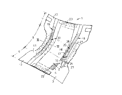
Fig. 1 is a plan view showing a disposable diaper 1 as
partially broken away and Fig. 2 is a perspective view of the
diaper 1 as partially broken away. Fig. 2 shows the diaper
1 as somewhat curved due to contraction of respective elastic
members as will be described later in more detail.
The diaper 1 includes a liquid-pervious topsheet 2, a
liquid-impervious backsheet 3 and a liquid-absorbent core 4
disposed between these two sheets 2, 3 defining a front waist
region 6, a rear waist region 7 and a crotch region 8
extending between the front and rear waist regions 6, 7. The
topsheet 2 and the backsheet 3 extend outwards beyond
peripheral edges of the absorbent core 4 and are joined
together along these extensions to form a pair of
transversely opposite side flaps 11, 11 and a pair of
longitudinally opposite end flaps 12, 13. The respective
side flaps 11, 11 are provided on their upper surfaces with
barrier cuffs 19. Each of these barrier cuffs 19 comprises
a proximal section 10 defining an upper surface of the side
flap 11, a supporting wall section 16 extending upwardly of
the diaper 1 from the proximal section 10, and a sealing
surface zone 20 which includes, in turn, a first overhang
section 17 extending inwardly of the supporting wall section
16 and a second overhang section 18 extending outwardly of
CA 02266287 1999-03-23
-6-
said supporting wall section 16. The barrier cuff 19
longitudinally extends along the crotch region 8 into the
front and rear waist regions 6, 7. Longitudinally opposite
ends of the first and second overhang sections 17, 18,
respectively, are joined to an inner surface of the diaper 1.
In the crotch region 8, the side flap 11 is provided with a
plurality of elastic members 21 extending longitudinally of
the side flap 11 so as to be operatively associated with each
leg-opening. These elastic members 21 are disposed between
the topsheet 2 and the backsheet 3 or, as shown in Fig. 2,
between the backsheet 3 and the proximal section 10 joined on
an upper surface of the extension of the backsheet 3 and
secured under appropriate tension between them. The end
flaps 12, 13, on the other hand, are respectively provided
with elastic members 22, 23 made of a foamed polyurethane
sheet extending circumferentially of the diaper 1. These
elastic members 22, 23 are intermittently secured with
appropriate tension between the topsheet 2 and the backsheet
3. The sealing surface zone 20 contains a plurality of
elastic members 24 extending longitudinally of the diaper 1
and secured under appropriate tension to the sealing surface
zone 20.
Fig. 3 is a fragmentary sectional view of the diaper 1
CA 02266287 1999-03-23
_7_
taken along line III-III in Fig. 2. The elastic members 24
contained in the sealing surface zone 20 include a first
elastic member 24A longitudinally extending in the first
overhang section 17 along an inner edge 26 of the sealing
surface zone 20 a second elastic member 24B longitudinally
extending in the second overhang section 18 along an outer
edge 27 of the sealing surface zone 20 and third elastic
members 24C lying between the outer edge 27 and the
supporting wall section 16. These third elastic members 24C
also extend longitudinally of the sealing surface zone 20.
While the first overhead section 17 is provided with the
single elastic member 24A in the embodiment shown in Fig. 3,
it is possible to provide a plurality of such elastic members
24A. In the case of Fig. 3, the first elastic member 24A
lies adjacent a top end of the supporting wall section 16,
preferably in a range of 0 - 3 mm, and more preferably in a
range of 0.5 - 2 mm from the top end. With the diaper 1
developed longitudinally of the diaper 1 as seen in Fig. 1,
the first and second elastic members 24A, 24B extend between
longitudinally opposite ends of the first and second overhead
sections 17, 18, respectively, substantially over an
identical length. The first elastic member 24A preferably
has an elongation stress higher than that of the second
CA 02266287 1999-03-23
_g_
elastic member 24B, more preferably an elongation stress and
an elongation percentage both higher than those of the second
elastic member 24B. The third elastic members 24C have a
length substantially identical to or shorter than those of
the first and second elastic members 24A, 24B. The third
elastic members 24C have an elongation stress identical to or
lower than that of the second elastic member 24B and an
elongation percentage identical to or higher than that of the
second elastic member 24B.
The topsheet 2 and the backsheet 3 are joined together
in a water-tight manner along their extensions outwards
beyond the peripheral edge of the absorbent core 4 by means
of hot melt adhesive 30. The backsheet 3 extends further
outwards beyond transversely opposite side edges of the
topsheet 2 and the proximal section 10 forming a part of the
barrier cuff 19 is joined to the outward extension of the
backsheet 3 preferably in a water-tight manner by means of
hot melt adhesive 30. The proximal section 10 extends
inwardly of the diaper 1 so as to be placed upon the topsheet
2 and joined thereto preferably in a water-tight manner by
means of hot melt adhesive 30.
With the barrier cuff 19 constructed as has been
described above, the first, second and third elastic members
CA 02266287 1999-03-23
-9-
24A - 24C are stretched and placed against the inner surface
of the diaper 1 as the diaper 1 is longitudinally developed
(See Fig. 1). When the diaper 1 is longitudinally curved
with the topsheet 2 inside, the first and second elastic
members 24A, 24B predominantly contract due to their
relatively high elongation stresses as well as elongation
percentage (See Fig. 2) so that the supporting wall section
16 of the barrier cuff 19 rises on the side flap 11 and the
sealing surface zone 20 is inclined towards the first
overhead section 17 (See Fig. 3). The third elastic members
24C serve to prevent the sealing surface zone 20 from
slackening between the first and second elastic members 24A,
24B. The first overhead section 17 cooperates with the
supporting wall section 16 to form a pocket 31 opening
downwards and inwardly of the diaper 1.
The outer edge 27 of the sealing surface section 20 as
the important part of the risen barrier cuff 19 comes in
contact with a wearer's leg indicated by imaginary lines as
the diaper is put on the wearer's body. With the outer side
edge 27 being more tightly placed around the wearer's leg,
the sealing surface zone 20 swings in a direction indicated
by an arrow X around the first elastic member 24A having the
highest elongation stress and, as indicated by imaginary
CA 02266287 1999-03-23
-10-
lines, is placed against the wearer's leg 32' over its
circumferential area as large as possible, whereupon the
pocket 31 is opened as largely as possible.
The diaper 1 of such arrangement enables the supporting
wall section 16 to obstruct an amount of body fluids tending
to flow laterally and thereby to prevent sideways leakage.
An amount of body fluids flowing along the supporting wall
section 16 to its top end is prevented by a lower surface of
the first overhead section 17 from entering into a gap
defined between the wearer's leg 32 or 32' and the sealing
surface zone 20. Even if an amount of body fluids entering
into the gap, it never happens that the amount of body fluids
might easily arrive at the exterior of the diaper 1 since the
barrier cuff 19 has the relatively large sealing surface zone
20 adapted to fit around the wearer's leg. Such effective
function of the barrier cuff 19 achieves the diaper 1
substantially free from leakage of body fluids.
The first overhead section 17 is not limited to the
specific embodiment as has been described above. For
example, it is also possible to provide a plurality of
elastic elements 24 extending in parallel one to another.
While these elastic members 24A may be identical in their
length as well as elongation percentage and their elongation
CA 02266287 1999-03-23
-11
stress also may be identical, the elongation stress is
preferably adjusted so that the elastic member 24A lying
nearer the inner edge 26 of the sealing surface zone 20 may
have correspondingly higher elongation stress. If it is no
imperative to prevent the sealing surface zone 20 from
slackening between its inner and outer edges 26, 27, the
third elastic member 24C may be eliminated.
The supporting wall section 16 and the sealing surface
zone 20 of the barrier cuff 19 are made of a nonwoven fabric
or a plastic sheet, preferably of a liquid-impervious
nonwoven fabric or a plastic sheet and more preferably of a
breathable/liquid-impervious nonwoven fabric or a plastic
sheet. The topsheet 2 may be made of a liquid-pervious
nonwoven fabric or a apertured plastic sheet. The backsheet
3 may be made of a liquid-impervious plastic sheet and the
absorbent core 4 may be made of fluff pulp or a mixture of
fluff pulp and superabsorptive polymer particles. The
respective elastic members of the diaper 1 may be secured to
the sheet members by means of hot melt adhesive. The
different sheets may be joined together by means of hot melt
adhesive or use of heat-seal technique.