Note: Descriptions are shown in the official language in which they were submitted.
CA 02266814 1999-03-24
BACKGROUND OF THE INVENTION
(a) Field of the Invention
The invention relates to a method of preparing a cored wire suitable for use
in
coating metallic articles which are exposed to erodent particles. In
particular, the
invention relates to deposition of an erosion resistant coating which is
comprised
of larger ferroboron phases bound with a ductile metallic phase, said ductile
metallic phase having a low affinity for oxygen.
(b) Description of the Prior Art
Solid particle erosion is defined as the! progressive loss of material from a
solid
surface that results from repeated impaci: of solid particles. Solid particle
erosion
is to be expected whenever hard particles are entrained in a gas or liquid
medium
impinging on a solid at any significant velocity, generally greater than 1
m/s.
Manifestations of solid particle erosiori include thinning of components, a
macroscopic scooping appearance following the gas-particle flow field, surface
roughening which severity depends on particle size and velocity, lack of
directional
grooving characteristic of abrasion and, in some cases, the formation of
ripple
patterns.
JJ:vs 1
CA 02266814 1999-03-24
The distinction between erosion and abrasion should be clarified, because
terms are very often misunderstood ancl situations not adequately classed.
Solid
particle erosion refers to a series of particles striking and rebounding from
the
surface, while abrasion results from the sliding of abrasive particles across
a
surface under the action of an externally applied force. The clearest
distinction is
that, in erosion, the force exerted by the particle on the material is due to
their
deceleration, while in abrasion it is externally applied and constant.
Therefore, erosion is affected by -three types of variables: impingement
variables describing the particle flow (velocity, impingement angle and
particle
concentration), particle variables (particlo) shape, size, hardness and
friability) and
material microstructure. The velocity of erodent has a marked influence on the
rate of material removal. It is generally admitted that the rate of erosion
exponentially (the exponent being betwe(,m 2 and 2.5 for metals and 2.5 and 3
for
ceramics) increases with the velocity. Angular particles produce erosion rates
higher than rounded ones. The hardness of erodent particles relative to the
material being eroded should be considered.
Depending on their nature, materials have a different response to erosion.
Material removal in ductile material involves large plastic flow while, in
ceramics
fracture is of primary importance, particularly for higher incidence angles.
Solid
particles impacting metals form plastic irripact craters and displace
material. At
low incidence angles, the displaced material is thereafter cut and removed by
a
JJ:vs 2
CA 02266814 1999-03-24
mechanism known in the scientific literature as "platelet mechanism". Metallic
materials present higher erosion rate at low impact angle than at high impact
angle. Conversely, ceramics are more damaged at high impact angles than at low
impact angles and present erosion peak at 900. In their case, the mechanism of
material removal involves cracks initiated by brittle fracture for erosion at
normal
incidence angle.
Thus, for particles impacting at low velocity hard materials are usually
considered at low impact angle but elastic materials should be selected at
high
impact angle. For higher particle velocity hard materials with some toughness
are
selected for low impact angle and resilient materials showing a compromise
between strength and ductility are chosen for high impact angles. Resilience
is
required to resist penetration of the surface by impacting particles.
Therefore, the
selection of materials to resist erosion depends on the angle at which the
particles
strike the surface and the impact velocity.
Two-phase materials such as high chromium white cast irons and Stellites
might be expected to exhibit high erosion resistance. It could be expected
that
such alloys could combine the relatively good erosion of hard ceramic phase
with
the desirable ductility and toughness of a metal. Though these alloys provide
excellent abrasion resistance, under mos-t erosion conditions they exhibit
little or
no improvement over plain carbon steels or pure metals. There is a synergetic
increase of the erosion of hard and brittle phase by its presence as a
dispersed
JJ:vs 3
CA 02266814 2004-04-15
phase in a relatively soft metal matrix. As an example, the eroded surface of
white cast iron by quartz sand shows that primary carbide are deeply depressed
below the surface.
Erosion is considered as a serious problem in many engineering systems such
as steam and jet turbines, pipelines and valves carrying particulate material
and
fluidized bed combustion systems. Generally speaking, machinery for use in
processing and transportation of fluids containing solid particles are exposed
to
damage resulting from erosion. Processing machines for processing resins
containing glass fibers, carbon fiber, asbestos or iron oxide; slurry pumps
for fluid
transportation of ore or coal; pipelines for transporting slurries and so
forth are
examples of industrial machinery that are damaged by solid particle erosion.
Particularly, high-temperature fluidized bed metal components exposed to
temperatures up to 500 C and process fans that aspirate gas having
temperatures
that reach 350 C suffer extensive material wastage. Heat exchanger tubes in
fluidized bed combustors experienced relatively high wastage rate at low
temperature (250 C). The wastage rate increases with the temperature and the
particle velocity. Peak wastage rates are observed for 347 stainless steel at
450 C, for Incoloy* 800H at 450 C, for mild steel at 300 C, for 1 Cr-0.5Mo
steel
at 400 C, for 2.25Cr-1 Mo at 400 C, for 722M24T steel at 400 C. At
temperatures above 100 C, erosion enhances oxidation. The wastage involves the
formation and removal of oxide by impacting particles. At these temperatures,
*Trade-mark
4
CA 02266814 1999-03-24
thin oxide layers are formed at much greater rates than would be the case
during
static oxidation. Impacting particles repeatedly take off thin oxide layers,
the
exposed metallic surface being readily oxidized. Therefore, in these
conditions,
erosion accelerates the oxidation of mai:erials.
In process fans used in pelletizing plE nts to re-circulate hot gas containing
iron
ore particles, the same type of wastage is observed. Iron ore pellets are
sintered
in continuous large industrial oil-fired furnaces. From the furnace, large
volumes
of hot gas are sucked by powerful fans. I3eing exposed to gas-borne iron
particles
and temperatures ranging between 1 25 C and 328 C fan components are rapidly
deteriorated. Extensive part repair or replacement are required for
maintaining a
profitable operation.
Cobalt- and nickel-bonded tungsten carbide coatings as well as nickel-bonded
chromium carbide have been widely adopted in various applications because of
their wear resistance. Unfortunately, these coatings are applied using
expensive
high velocity oxy-fuel and plasma spraying techniques. In addition, these
coating
techniques are not suited for on-site applications, particularly in restricted
areas.
These materials contain strategic, price-sensitive elements such as nickel,
chromium and tungsten and/or do not necessarily offer the best erosion
resistance
in applications mentioned above. These elements (WC) are either strategic or
scarce, so that the carbide materials are price sensitive. In addition,
elements
contained within these materials present some toxicity restricting their use
in some
JJ:vs 5
CA 02266814 1999-03-24
applications, requiring expensive health protection equipment and limiting
personnel exposure to toxic dust.
There are many workers that have previously proposed materials based on iron
and iron borides for different applicatioris.
Kondo, Okada, Minoura and Watanabe in (U.S. Pat. No. 3,999,952) (1976)
proposed a method to produce a sintered hard alloy, prepared from a hard alloy
powder comprising iron boride or iron muiltiple boride in which a part of iron
boride
is substituted by a non-ferrous boride or multiple boride.
In a subsequent patent (U.S. Pat. No. 4,194,900) (1980) Ide, Takagi,
Watanabe, Ohhira, Fukumori and Kondo proposed a modification in the method for
producing the hard alloy powder by usirig different raw materials for
improving
strength and hardness. In these works, hard alloys are produced by crushing
the
hard alloy powder, pressing the milled powder and sintering the compact under
vacuum or controlled atmosphere.
Ide, Kawamura, Ohhira, Watanabe and Kondo in Jap. Pat. No. Sho (1983)-
101622 proposed a method of using hard sintered alloys of the iron-based
complex series in combination to form paired metals. The hard phase of these
alloys contains 35-96 wt. % iron-based complex boride with the remaining
consisting of one or more of Cr, Fe, Mo, W, Ti, V, Nb, Ta, Hf, Zr, Ni, Co, Mn
or
the alloys of these metals to form the bonding phase. Sliding wear properties
of
JJ:vs 6
CA 02266814 1999-03-24
the sintered alloys against metals were evaluated using the Ohgoshi sliding
wear
tester.
Watanabe, and Shimizu in U.S. Pat,, 4,259,119 (1981) proposed a sintered
body suitable as abrasive material comprising 70 to 99.99 % of a combination
of
at least two kinds of metal borides selected from the group consisting of
diborides
of Ti, Ta, Cr, Mn, Mo, Y, Hf, Nb, Al and' Zr and from 0.01 to 30% by weight of
a metal boride or borides selected from the group consisting of borides of
nickel,
iron and cobalt.
Watanabe and Kono in U.S. Pat. 4,292,081 (1981) proposed sintered
refractory and abrasive bodies composed of titanium diboride, chromium
diboride,
tantalum diboride with minor amounts of metal borides such as MnB, Mn3B41
Mn2B, Mn4B, TiB, Ti2B5, W2B5 and MoZBS. In the preparation of sintered bodies
iron boride, nickel borides and cobalt borides are also added to favour liquid
phase
sintering. Watanabe et al. in U.S. Pat. No. 5,036,028 proposed a high density
metal-boride based ceramic sintered bociy composed of at least: a) TiB21 ZrB21
CrB2, HfB21 VB2, TaB2, NbB21 MoB21 YB2, AIB2, MgB2, CrB, VB, TaB, NbB, MoB,
HfB, YB, ZrB, HfB, TiB, MnB, W2B5 and Mo2B5; b) 0.1 to 10 wt. % of cobalt
boride, nickel boride or iron boride and c) 0.1 to 10 wt. % of a double
carbide
comprising Ti, Zr, Wand C, ZrCN, HfCN or a double carbo-nitride comprising Ti,
Zr,
Hf and C,N.
JJ:vs 7
CA 02266814 2004-04-15
Jandeska and Rezhets in U.S. Pat. 4,678,510 (1987) proposed a wear
resistant iron alloy article formed by compacting and sintering a
predominantly iron
powder mixture containing additions of C, Cu and nickel boride. The product
microstructure comprises hard borocementite particles dispersed in a
martensitic
or pearlite matrix. The particles have a cross-sectioned dimension greater
than
1,um, in an amount preferably between 10 and 30 volume percent to improve the
wear resistance. This material was developed for automotive gears.
Saito and Kouji in EP 659,894 A2 (published June 28, 1995) proposed a high
modulus iron-based alloy comprising a matrix of iron or iron alloy and one
boride
selected from the group consisting of borides of group Iva elements, and
complex
borides of group Va element and iron dispersed in the matrix. The iron based-
alloy
is obtained by sintering at temperature of 1000 to 1300 C. The sintered
product
is undesirably likely to form liquid phase above 1300 C. In samples 13-15,
Fe-17Cr is mixed with ferrotitatium and ferroboron powders.
Miura, Arakida, Kondo and Ide in U.S. Pat. 4,427,446 (1984) proposed a
wear-resistant composite material for use in centrifugally cast linings. The
matrix
metal is an oxidation-resistant nickel or cobalt alloy and the reinforcing
material is
a boride or a composite boride composed of chromium, iron and boron. The
matrix
used is either a Ni-Cr-B-Si based self-fluxing alloy or a Co-Ni-Cr-W-B-Si
based
self-fusing alloy. According to the inventors, the self-fluxing properties of
alloys
which melt at temperature comprised between 950 and 1250 C is the key point
8
CA 02266814 1999-03-24
of their process. The cylinder containing a powder mixture comprising the
self-fluxing alloy and the reinforcement is first heated to the melting
temperature
of the alloy. Placed in a centrifuge, the melt is allowed to cool slowly.
After
cooling, the inner surface is rich in reinf'orcing particles.
Clark and Sievers in U.S. Pat. No. 4,389,439 (1983) proposed a different
lining for tubes and cylinders. They proposed a composite tubing comprising an
iron boride layer formed in situ by the diffusion of boron into iron. The
diffusion
coating obtained has an inner layer comprising dispersed iron carbide and an
outer
layer consisting of iron boride.
Sanchez-Caldera, Lee, Suh and Chun in U.S. Pat. No. 5,071,618 (1991)
proposed a method for manufacturing a dispersion-strengthened material based
on
a metal matrix with a containing elemerit capable of reacting with boron and a
second metal containing metal and boron. The material is produced by injecting
the two metal in liquid state at two different speeds. It produces materials
containing boride particles having an average size of 0.2 Nm.
Dallaire and Champagne in U.S. Pat. No. 4,673,550 (1987) proposed a
process for synthesizing TiB2 composite rriaterials containing a metallic
phase. The
preparation of these composites comprises providing mixture titanium alloys
which
in addition contain Fe, Ni, Al, Mo, Cr, Co, Cu or mixtures thereof and boron
or
ferroboron. After heating, it results iri the synthesis of composite material
JJ:vs 9
CA 02266814 1999-03-24
containing fine TiBZ crystals dispersed in a metallic matrix. Coatings applied
by
plasma spraying possess excellent abrasion wear resistance.
Jackson and Myers in U.S. Pat. No. 3,790,353 (1974) proposed a hard facing
pad usable, for example, by brazing to a digger tooth or the like. The wear
pad is
from 70 to 85 per cent per volume particles of cemented carbide in a metal
matrix
having a melting point not substantially liigher than the melting point of the
metal
cementing the carbide.
Tagaki, Mori, Kawasaki and Kato in U.S. Pat. No. 5,004,581 (1991) proposed
a dispersion strengthened copper-base alloy for wear resistant overlay formed
on
a metal substrate consisting in 5-30 wt. % Ni, 0.5-3 wt. % B, 1-5 wt. % Si, 4-
30
wt. % Fe, 3-15 wt. % Sn or 3-30 wt. % An, the remaining being copper. It forms
boride and silicide of the Ni-Fe system ciispersed in a copper-base matrix.
This
material is expected to provide a superiior wear-resistance to slide abrasion
as
evaluated by the Ohgoshi abrasion tester.
Gale, Helton and Mueller in U.S. Pat. iNo. 3,970,445 (1976) proposed a wear-
resistant alloy comprising boron, chromiurn an iron having high hardness
produced
by rapidly cooling and solidifying spheroidal particles of the molten alloy
mixture.
The resultant particles are cast in the desired form or incorporated into a
composite alloy wherein the solid particles are held together with a matrix of
different material from the alloy. This alloy was designed for use in abrasive
environments (ground-engaging tools). The composite particles comprise
JJ:vs 1 Q
CA 02266814 1999-03-24
25-61 wt. % chromium, 6-12 wt. % boron and the balance iron and are produced
by melting.
Helton, Gale, Moen, Mueller, Pierce and Vermillion in U.S. Pat. No. 4,011,051
(1977) proposed spheroidal particles of wear-resistant alloy comprising boron,
chromium and iron with high hardness produced by the rapid cooling of a molten
alloy mixture. The resultant solid particles are then incorporated into a
composite
alloy wherein the solid particles are held together with a matrix of different
material from the alloy. Inserts of the alloy are useful in producing long
wearing
tools. The composite particles contain 25-70 wt. % chromium, 6-12 wt. % boron,
0-2 wt. % carbon, the remaining being iron. One of the brazing alloy consist
in
94.0 wt. % nickel, 3.5 wt. % silicon, 1.5 wt. % boron, 1.25 wt. % iron and
0.03 wt. % carbon.
Helton, Gale, Moen, Mueller, Pierce and Vermillion in U.S. Pat. No. 4,113,920
(1978) proposed a ground engaging tool resisting to wear including a contact
section for engaging the ground and at least a portion of said section
reinforced
with a wear resistant alloy, said wear resistant alloy comprising cast
spherical of
a first alloy embedded in a matrix of a second alloy in which said first alloy
is
soluble with difficulty and wherein the first alloy comprises from about
25-70 wt. % chromium, from about 6-12 wt. % boron, from about 0 to about
2 wt. % carbon, and iron is the balance. The matrix is a nickel based brazing
alloy. Mixed powders are jointed by conventional sintering processes.
JJ:vs 11
CA 02266814 1999-03-24
Moen in U.S. Pat. No. 4,066,422 (1978) proposed a wear-resistant composite
material and method of making an article which is particularly adaptable for
use
with a ground engaging tool. The composite material comprises abrasive-wear
resistant particles embedded in a matrix consisting of about 3 to 5 wt. %
boron,
and the balance being iron having residuial impurities. The boron is
controlled to
a level of approximately 3.8 wt. % corresponding to the eutectic Fe-B
composition
which has the low melting temperature of 1161 C.
E.I. Larsen in U.S. Pat. No. 3,720,990 (1973) disclosed a molybdenum alloy
containing at least two metallic elements which form an alloy which melts at a
temperature considerably below that of r-riolybdenum and when in the molten
state
dissolves appreciable molybdenum during liquid phase sintering and which may
be
shaped before or after sintering, thus avoiding expensive hot working and/or
hot
forging.
Babu in U.S. Pat. No. 4,235,630 (1980) and Can. Pat. No. 1,110,881 (1981)
proposed a wear-resistant molybdenum-iron boride alloy having a microstructure
of a primary boride phase and a matrix phase. The primary boride phase
comprises
molybdenum alloyed with iron and boron, and the matrix phase comprises one of
boron-iron in iron and iron- molybdenum in iron. The alloy finds particular
utility
in a composite material on a ground-engaging tool. The alloy is densified by
sintering the article at a temperature sufficient for controlled formation of
a liquid
phase. The molybdenum-iron-boride alloy can be also crushed to form particles
JJ:vs 12
CA 02266814 1999-03-24
that can be bounded by a suitable matrix, such as the iron-boron matrix
composition described in U.S. Pat. No. 4,066,422 attributed to Moen. For
fabricating the sintered alloy Babu used in examples a preferred ferroboron
constituent containing 25 wt. % boron.
Dudko, Samsonov, Maximovich, Zelenin, Klimanov, Potseluiko, Trunov and
Sleptsov in Can. Pat. No. 1,003,246 (1977) proposed wear-resistant composite
materials for hard facing equipment sutijected to abrading. Particulate
material
containing 7-30 wt. % chromium, 40-60 wt. % titanium and 30-40 wt. % boron
having a size between 0.3 to 2 mm are embedded in a low-melting alloy matrix
to
ensure good wettability. Preferred alloys; contain: a) 30-65 wt. % copper, 10-
35
wt. % nickel and 10-35 wt. % manganese; b) 12-25 wt. % chromium, 1.5-4 wt.
% silicon, 1-4 wt. % boron, the balance being nickel.
Ray in U.S. Pat. No. 4,133,679 (1979) described glassy alloys containing iron
and molybdenum or tungsten, together with low boron content. The glassy alloys
consist essentially of about 5 to 12 atom percent boron, a member selected
from
the group consisting of about 25 to 40 atom percent molybdenum and about 13
to 25 atom percent tungsten and the balance iron plus incidental impurities.
The prior art references described aibove relate to compositions of matter
which differ from those of the subject application. Alternatively, the
physical
properties of the subject invention, namely hard ferroboron phases of
relatively
JJ:vs 1 ~
CA 02266814 1999-03-24
large area bound with a ductile metallic phase, provide an erosion resistant
coating
which is surprisingly superior to prior art coatings.
SUMMARY OF THE INVENTION
An object of the invention is thus to provide a oxidation-resistant and
erosion-
resistant composite material that is fornied by high temperature melting a
metal
possessing low affinity for oxygen with riequisite proportion of ferroboron
particles
of the required particle size. Raw materials are shaped in the form of a cored
wire
that is arc sprayed with air or deposited by welding techniques for producing
erosion-resistant coatings for componerits exposed to a high velocity blasts
of
large particles at temperatures up to 500 C.
The above object is attained by employing a ductile metal having low affinity
for oxygen such as iron, low carbon steel or ductile stainless steel with
coarse
ferroboron particles. The resulting coatings are composed of boride phases
having
mean sizes at least equal or larger than the sizes of erodent impacts.
Broadly, the invention comprehends an oxidation resistant and ductile metal
cementing boride particles which is formed by bringing the metal and boride
particles together at temperatures higher than the melting temperature of the
metal. The formed material is composed of large hard boride phases bonded by
resilient, ductile and oxidation-resistant metallic phases. It can be
preferably
obtained in the form of erosion-resistanl: coatings by arc spraying cored
wires
JJ:vs 14
CA 02266814 1999-03-24
composed of a sheath of the selected metal and a core comprising only the
boride
particies.
In particular, the invention comprises a two-phase composite coating having
select microstructural features. In preferred embodiments, coatings prepared
by
the process of the invention will contain hard boride phases bounded with a
ductile
metallic phase.
In said preferred embodiments, the exposed surface areas of the majority of
the hard boride phases will be greater 1:han the mean impacting surface of the
erodent particles. Additionally, the ductile metallic phases will, in
preferred
embodiments, be smaller in exposed surface area than the mean impacting
surface
of the erodent particles. Such embodiments of the invention will resist
erosion by
deflection of the erodent particles off of the hard boride phases. Further,
the
reduced surface area of the ductile metallic phase prevents ploughing of this
phase
by erodent particles and the plastic deformation which results therefrom.
The inventor has determined that the most damaging iron ore particles
typically range in size from 32-300 Nm in size and that the mean particle size
is 89
Nm. It has also been determined that with particles of this size, the mean
size of
impact in collisions with a relatively smooth surface corresponds to 14.5 Nm
in
maximum length. Accordingly, when the erodent particle is iron ore, the
inventor
has determined that a preferred embodirnent of the invention comprises a two
phase coating wherein the surface inclucles (a) hard ferroboron phases having
a
JJ:vs 1 ~;
CA 02266814 2004-04-15
surface area which generally corresponds to a geometric area having 14.5 pm in
length or greater and (b) a ductile metallic phase which houses the ferroboron
phases.
The ductile metallic phase must be selected from metals which have a low
affinity for
oxygen. Such metals, which have a Gibbs energy of about 70-117 kcal/mole 02,
include Cu, Bi, As, Sb, Co, Ni, Cd, and Fe. Further, the ductile metallic
phase should
have surface exposure in the regions between the ferroboron hard phases having
surface area sizes which correspond to circles having diameters less than
about
14.5 pm.
It has been determined that coatings having the above-mentioned
microstructural properties are most efficiently prepared by arc spraying or
deposition
by welding techniques. The components of the coating are provided in the form
of a
cored wire wherein the sheath is composed of the ductile metallic phase and
the
powdered core is composed of a coarse ferroboride powder. Advantageously, the
invention allows for on site deposition of the coating.
Descriation of the Drawings
Fig. 1: Schematic view of a device adapted to simulate accelerated
erosion.
Figs. 2, 3: Graphical representation of the effect of changes in arc voltage
on erosive volume loss at 25 C (Fig. 2) and 330 C (Fig. 3).
Figs. 4, 5, 6, 7: Graphical representation of the effect of changes in arc
amperage
on erosive volume loss at 25 C/31 Volts (Fig. 4),
16
CA 02266814 1999-03-24
330 C/31 Volts (Fig. 5), 25 C/35 Volts (Fig. 6) and
330 C/35 Volts (Fig. 7).
Figs. 8, 9: Graphical representation of the effect of changes in spray
distance on erosive volume loss at 25 C (Fig. 8) and
330 C (Fig. 9).
Figs. 10, 11: Graphical representation of the effect of changes in
transverse spray speed on erosive volume loss at 25 C
(Fig. 10) and 330 C (Fig. 11).
Fig. 12: Graphical representation of the effect of changes in the arc
amperage on the deposition rate.
Figs. 13, 14, 15, 16: Graphical representation of the effect of changes in the
wire load on the erosive volume loss at 25 C/31 Volts
(Fig. 13), 330 C/31 Volts (Fig. 14), 25 C/35 Volts
(Fig. 15) and 330 C/35 Volts (Fig. 16).
Figs. 17, 18, 19, 20: Graphical representation of the effect of changes in the
wire load on erosive volume loss at 25 C/25 impact angle
(Fig. 17), 330 C/25 impact angle (Fig. 18), 25 C/90
impact angle (Fig. 19) and 330 C/90 impact angle (Fig.
20).
JJ:vs 17
CA 02266814 1999-03-24
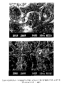
Fig. 21: Scanning electron micrographs of the surface of arc
sprayed coatings using cored wire P-3 (400 fold
magnification).
Fig. 22: Scanning electrori micrograph of a cross-section of an arc-
sprayed coating using cored wire P-3 (300 fold
magnification).
Description of Preferred Embodiments
Typically, the invention would be used on site to apply an erosion resistant
coating to a surface exposed to erodenl: particles, such as process fans or
heat
exchange tubes in fluidized bed ccimbustors. The apparatus depicted
schematically in Fig. 1 was designed to simulate an accelerated erosion
environment in which to compare the erosion resistance of various coatings.
This
apparatus allows the evaluation of erosive wear on samples at temperatures up
to
500 C. An alumina nozzle (1) having a diameter of 1.575 mm provides a well
localized stream of particles. Particle flovvrates were selected to avoid
particle-to-
particle collisions which would result in under evaluation of the extent of
erosion.
A particle feeder (2) delivers particles to a mixing chamber (3) at a constant
rate.
The particles are then accelerated toward a coated target (4) by compressed
air
delivered to the mixing chamber by a coil (5). The target is held in position
by an
adjustable sample holder (6) which allovvs for erosion tests at different
impact
angles. A furnace (7) is provided for testing at elevated temperatures.
JJ:vs 1 f;
CA 02266814 1999-03-24
To measure erosion at elevated temperatures, the sample holder was
introduced into the furnace 5 minutes prior to the introduction of erodent
particles
for impact angle tests at 90 and 10 minutes prior to impact angle tests at 25
.
The compressed air passes through the furnace-heated coil (5) thereby
elevating
the temperature thereof.
Erodent particles were comprised of oven dried iron ore particles which varied
in size from about 32 to about 300 Nm.
The measurement of particle speed was done with a laser anemometer and the
testing rig calibrated in order to obtain particle impact velocity of 100 m/s.
Table
1A gives the main parameters used during erosion tests.
Table 1A - Erosion test parameters
Erodent material Iron ore (-300 + 32,um)
Erodent flow rate 2.64 (+/-5%)g/minute
Erodent impact speed 96.49(+/-22)m/s
Testing Time 5 minutes
Test temperature ( C) 25 and 330 C
Wear damage was evaluated with a laser profilometer. This apparatus allows
measurements with an accuracy greater than 99%. The profilometer is designed
JJ:vs 1 q
CA 02266814 2004-04-15
to measure minute volume losses and microscopic deformation. Volume losses are
reported in mm3 per kilogram of erodent particles.
The coatings were deposited on metallic target material by arc spraying a
cored wire. The cored wire is comprised of a powdered core enclosed within a
drawn metal sheath.
Core powders, comprised of iron, ferroboron or boron or metallic additives
were mixed in a tumbler for 24 hours to evenly distribute particles of
different sizes
through the powder. The composition of each powder and the proportion of
particles of different sizes are recited in Table 1 B. The composition of
metals
which were used to prepare sheaths are shown in Table 1 C.
Table 1 B - Chemical Composition and Particle Size Distribution of Powders
Powder Composition Particle Size Distribution
Element Wt. % U.S. Mesh Sieve Size Wt. %
Size (Jum)
Atomet* 95D Iron 99.56 +200 +75 1.5
iron powder Oxygen 0.39 -200+325 45 2.5
Carbon 0.05 -325 -45 96.0
Atomet 95 Iron 99.79 +200 +75 2.5
iron powder Carbon 0.21 -200+325 45 7.0
-325 -45 90.5
*Trade-mark
CA 02266814 1999-03-24
Atomet 1001 HP Iron > 99 -250 + 150 10
iron powder Nickel 0.07 -150 + 106 17
Oxygen 0.06 -106 + 75 20
Chromium 0.05 -75+45 25
Copper 0.02 -45 28
Manganese 0.01'.i
Phosphorous 0.01
Vanadium 0.006
Aluminum 0.004
Sulfur 0.004
Carbon 0.004
Silicon 0.003
Titanium 0.001
Boron powder Boron 95-97 -5 100
(Cerac Inc.) Silicon 0.3
Magnesium 0.2
Iron 0.1
Calcium 0.1
Oxygen Balance
Ferroboron 1 Iron 80.149 +100 37
(Shieldalloy Corp.) Boron 17.90 +200 36
Aluminum 1.92 +325 14
Carbon 0.03 -325 13
Sulfur 0.001
Ferroboron 2 Iron 80.472'. + 100 34.0
(Metallurg Ltd.) Boron 19.00 +200 33.0
Carbon 0.31 +325 17.0
Silicon 0.20 -325 16.0
Sulfur 0.002
Phosphorous 0.016
Ferroboron 3 Iron 80.58 + 100 43.0
(Metallurg Ltd.) Boron 18.80 +200 35.0
Carbon 0.149 +325 11.0
Silicon 0.46 -325 11.0
Sulfur 0.002
Phosphorous 0.009
Ferroboron 4 Iron 81.14 + 100 28.0
(Metallurg Ltd.) Boron 18.60 +200 38.0
Carbon 0.03 +325 18.0
Silicon 0.21 -325 16.0
Sulfur 0.003
Phosphorous 0.02
JJ:vs 21
CA 02266814 1999-03-24
Table 1 C - Composition of metals used to prepare the sheath of cored wires.
Metal Composition
Element Wt. %
1074 Steel Czirbon 0.740
Manganese 0.670
Chromium 0.220
Silicon 0.210
Nickel 0.020
Phosphorous 0.010
Sulfur 0.002
liron Bal.
1008 Steel Manganese 0.210
Carbon 0.040
Alurninum 0.034
Stilfur 0.012
Silicon 0.010
Phosphorous 0.009
Iron Bal.
1005 Steel Manganese 0.2
Carbon 0.03
Sudfur 0.05
Phosphorous 0.04
Iron Bal.
304 Stainless Steel Chromium 18.54
Nickel 9.52
Manganese 1.41
Silicon 0.53
Copper 0.36
Molybdenum 0.26
Carbon 0.06
Nitrogen 0.04
Phosphorous 0.03
Sulfur 0.001
Iron Bal.
430 Stainless Steel Elennent 16-18
Chromium 1.0
Manganese 1.0
Silicon 0.12
Carbon 0.04
Phosphorous 0.03
Sulfur Bal.
Iron
JJ:vs 22
CA 02266814 2004-04-15
A-1 Kanthal* Alloy Element 22
Chromium 5.8
Aluminum Bal.
Iron
In a preferred embodiment of the invention, the metal sheath of the cored wire
is derived from a metal strip which is about 0.254 or 0.127 mm thick and about
10.16 mm wide. The metal strip is drawn through a series of standard wire
drawing dies aligned in descending order of diameter on the orifice. At the
stage
where the metal strip forms a "U" shape, a powdered mixture is introduced into
the "U" shaped metal channel. The metal strip is then drawn through additional
standard dies which seal the edges of the strip with an overlapping joint. The
cored wire is then drawn to a final diameter of about 1.60 mm to achieve
favourable compacting of the enclosed powder.
Are spraying experiments were carried out with the above-described wires
using a commercial Miller BP 400* Arc Spray System under ambient atmosphere.
Coatings can be obtained by spraying with different gases as the atomizing
gases.
Air was preferred because of its availability and low cost.
For all experiments, the spraying conditions are indicated in Tables 3, 4 and
9-15. Voltage mentioned was almost stable during the arc spraying operation.
For
comparison purposes, arc sprayed coatings were also fabricated by spraying
commercial wires. Their erosion resistance was evaluated by the same
*Trade-mark
23
CA 02266814 1999-03-24
method that was used with cored wires prepared according to the invention.
EXAMPLE 1 to 46, P-1 to P-6
The powder mixtures required for forming the core of the wires were blended
in a tumbler for 24 hours. The resultinig powder mixtures were each loaded in
a
metal strip to form after cold drawing a 1/16 inch (1.6 mm) diameter cored
wire.
One wire sample was cold drawn to 2.3 mm. The cored wires containing a
loading percentage of the powder mixture were arc sprayed to form thick
coatings.
The coatings were erosion-tested using the blast type device depicted in Fig 1
using iron ore as erodent. The volume loss was measured with the laser
profilometer. The composition of cored vvires for the different examples are
shown
in Table 2, the spraying parameters in Tables 3 and 4; the results of erosion
tests
expressed in mm3 per kilogram of iron ore striking the material are shown in
Tables
5 and 6.
Table 2 - Composition and characteristics of cored wire samples
Wire Sheath Core Core Core Core Wire
sample material/ wt % loading
thickness wt %rron wt %/ wt % other
(thousand of type ferroboron boron elements (wt %)
an inch) type
1 1074/0.005 70.92/ 24.66/ferroboron 1 4.42 - 51.2
Atomet ( - 15 pm)
1001HP
2 1074/0.005 91.2/Atomet - 8.8 - 50.9
1001 H P
JJ:vs 24
CA 02266814 1999-03-24
3 1074/0.005 - 60/ferroboron 1 - - 49.3
( - 100 + 38 pm)
40/ferroboron 1
(-15pm)
4 1074/0.005 88/Atomet 12 - 44.4
1001HP
1074/0.005 20/Atomet 48/ferroboron 1 - - 51.9
95 (-100+38pm)
32/ferroboron 1
(-15pm)
6 1074/0.005 40/Atomet 60/ferroboron 1 - - 42.9
95 ( - 15 pm)
5 7 1074/0.005 94/Atomet - 6 - 53.6
1001HP
8 1074/0.005 48/Atomet 48/ferroboron 1 2 - 47.7
95 (-75 + 38Nm)
9 1074/0.005 40/Atomet 36/ferroboron 1 - - 51.5
95 ( - 100 + 38 pm)
24/ferroboron 1
(-15pm)
1074/0.005 15/Atomet 85/ferroboron 1 - - 50.6
95 ( - 15 pm)
11 1074/0.005 60/Atomet 40/ferroboron 1 - - 52.4
95 ( - 15 pm)
10 12 1074/0.005 20/Atomet 80/ferroboron 1 - - 44.52
95 ( - 38 pm)
13 1074/0.005 45.6/Atomet 50/ferroboron 1 4.4 - 37.4
95 ( - 38 pm)
14 SS 304/0.005 44.14/ 5,5.86/ferroboron 1 - - 39.7
Atomet 95 ( - 15 pm)
SS 304/0.005 91.2/Atomet - 8.8 - 53.8
1001HP
16 1074/0.005 91.2/Atomet - 8.8 - 41.3
1001HP
15 17 1074/0.005 66/Atomet - 9 25 Cr 39.2
18 1008/0.01 - 100/ferroboron 1 - 31.6
(-38pm)
JJ:vs 25
CA 02266814 1999-03-24
19 1074/0.01 - 100/ferroboron 1 - - 44.2
(- 38 pm)
20 1008/0.01 - 99.6/ferroboron 1 - 0.4 C 31
(-38pm)
21 1008/0.01 20/Atomet 80/ferroboron 2 - - 33.3
95D (-75pm)
22 1008/0.01 35/Atomet 65/ferroboron 2 - - 39.2
95D ( - 150 pm)
23 1008/0.01 - 100/ferroboron 2 - - 40.6
( - 150 pm)
24 1074/0.01 35/Atomet 65/ferroboron 2 - - 29.3
95D ( - 75 Vm)
25 1074/0.01 20/Atomet 80/ferroboron 2 - - 34.4
95D ( - 150 pm)
26 1074/0.01 - '100/ferroboron 2 - - 37.13
( - 150 pm)
27 1008/0.01 - '100/ferroboron 2 - - 41.3
( - 150 + 32 Nm)
28 1008/0.01 20/Atomet 80/ferroboron 2 - - 35.9
95D ( - 150 + 32 pm)
29 1008/0.01 - 1100/ferroboron 2 - - 42.4
30 1008/0.01 - 11 00/f erroboron 2 - - 42.6
( + 32 pm)
31 1008/0.01 - 1 00/ferroboron 3 - - 42.3
( - 150 + 32 pm)
32 1008/0.01 - 98/ferroboron 2 2 - 37.3
33 S.S. 430/0.01 - 1 00/ferroboron 3 - - 41.8
34 1008/0.01 - 96/ferroboron 3 - 4 Sn 37.8
35 1008/0.01 - 100/ferroboron 4 - - 33.9
36 1008/0.01 - 100/ferroboron 4 - - 43.8
37 S.S. 304/0.01 - 100/ferroboron 4 - - 40.8
39 Kanthal - 100/ferroboron 3 - - 38.3
A-1 /0.01
40 1008/0.01 - 100/ferroboron 2 - - 46.5
JJ:vs 26
CA 02266814 1999-03-24
41 1008/0.01 - 100/ferroboron 2 - - 41.6
42 1008/0.01 - 100/ferroboron 2 - - 38.7
43 1008/0.01 - 100/ferroboron 2 - - 34.8
44 1008/0.01 - 100/ferroboron 2 - - 29.2
45 1008/0.01 - 100/ferroboron 2 - - 25.6
P-1 1005/0.01 - 100/ferroboron 2 - - 35.27
- 150 + 32 pm)
P-2-A 1005/0.01 - 100/ferroboron 3 - - 38.75
( - 150 + 32 pm)
P-2-B 1005/0.01 - 100/ferroboron 3 - - 38.3
(-150+32Nm)
P-2-C 1005/0.01 - 100/ferroboron 3 - - 37.63
( - 150 + 32 pm)
P-3 1005/0.01 '1 00/f erroboron 3 - - 39.5
P-5 1005/0.01 - 100/ferroboron 3 - - 37.4
P-6 1005/0.01 - '100/ferroboron 4 - - 34.9
46 1008/0.01 - 1100/ferroboron 2 - - 48.2
wire
diameter
2.3mm
Table 3 - Spraying parameters of cored wires.
Cored wire Arc voltage Arc current Spray distance Transverse
number (V) (A) (cm) spray speed
(cm/s)
1 27.5 100 10.2 30
2 27.5 105 10.2 30
3 29 100 10.2 30
4 27.5 100 10.2 15
5 29 'I 00 10.2 15
6 29 100 10.2 15
7 29 '100 10.2 15
JJ:vs 2,7
CA 02266814 1999-03-24
8 29 100 10.2 15
9 29 100 10.2 15
30.5 100 10.2 15
11 29 100 10.2 15
5 12 29 100 10.2 15
2-12 29 100 10.2 15
13 29 100 10.2 15
14 30 100 10.2 15
33 100 10.2 15
10 16 30 100 10.2 15
17 30 100 10.2 15
18 30 100 10.2 15
19 30 100 10.2 15
30 100 10.2 15
15 21 30 100 10.2 15
22 30 100 10.2 15
23 30 100 10.2 15
24 30 100 10.2 15
30 100 10.2 15
20 26 30 100 10.2 15
27 30 100 10.2 15
28 30 100 10.2 15
29 30 100 10.2 15
30 100 10.2 15
25 31 30 100 10.2 15
31 31 150 7.62 15
32 30 100 10.2 15
33-1 30 100 7.62 15
33-2 35 200 7.62 15
JJ:vs 28
CA 02266814 1999-03-24
33-3 31 200 7.62 15
34 30 100 7.62 15
35 31 200 7.62 15
36 31 200 7.62 15
37-1 31 200 7.62 15
37-2 35 200 7.62 15
39-1 31 200 7.62 15
39-2 30 100 7.62 15
46 35 - 225 7.62 15
Pilot 2-A,B,C 31 200 7.62 15
P-3 31 200 7.62 15
P-6 31 200 7.62 15
To investigate the effect of arc current, spray distance and transverse spray
speed on the resultant coatings, one cored wire embodiment of the invention
(P1 )
was deposited under different spraying conditions (Table 4). The erosion rates
for
these coatings are shown in Table 5. The results demonstrate that an increase
in
arc current and hence an increase in the deposition rate produces a coating
with
improved erosion resistance. A reduce spray distance also improves the
coating.
In preferred embodiments, the spraying ciistance will be maintained at about
7.5-
10.5 cm. The transverse spray speed dcies not significantly affect the
properties
of the coatings. Additional results of erosion volume loss under varied
spraying
conditions are reported in Tables 9-15. The results, represented graphically
in
Figs. 2-12 confirm that coatings done with high arc voltage and amperage, low
spray distance and low transverse spray speed resulted in low volume loss at
both
JJ:vs 29
CA 02266814 1999-03-24
impact angles of 25 and 90 and temperatures of 25 C and 330 C. The effect
of wire load is shown in Tables 14 and 15 and is represented graphically in
Figs.
13-20. The eroded volume loss of sprayed coatings decreased as the wire load
increased for all the erosion conditions tested. Fig. 21 comprises two
scanning
electron micrographs of a surface that has been coated with embodiment P-3 of
the invention. Scanning electron micrographs of cross-sections of a coated
surface are shown in Fig. 22. These figures show that coatings presented
ferroboride phases (shown in dark contrast) larger than the mean particle
impact
damage size of 14.5 mm.
Table 4 - Spraying parameters for pilot cored wire (P-1).
Coating Arc voltage Arc cijrrent Spray Transverse
designation (V) (A) distance spray speed
(cm) (cm / s)
P1-01 30 100 10.2 15
P 1-02 30 100 20.3 60
P1-03 32 100 10.2 60
P1-04 32 100 20.3 15
P1-05 31 150 7.62 15
P1-06 31 150 15.24 30
P1-07 31 200 7.62 30
P1-08 31 200 15.24 15
P1-09 31 200 7.62 15
JJ:vs 30
CA 02266814 1999-03-24
Table 5 - Erosion volume loss of arc sprayed coatings done with Pilot wire 1
of this
invention at 25 C and 330 C for impact angles (a) of 25 and 90 .
Coating Temp. =25 C Temp. =25 C Temp. =330 C Temp. =330 C
designation a = 90 a = 25 a = 90 a = 25
(mm'/kg) (mm'/kg) (mm'/kg) (mm'/kg)
P1-01 46.7 18.6 29.8 15.6
P1-02 96.1 37.4 42.0 23.3
P1-03 57.2 18.2 29.3 18.3
P1-04 64.8 33.9 39.9 21.9
P1-05 24.7 10.3 18.5 11.7
P1-06 52.2 13.2 26.4 18.3
P1-07 23.5 8.2 17.0 7.7
P1-08 31.0 10.9 24.9 11.5
P1-09 25.0 8.3 14.7 9.6
Erosion test results for common metals and alloys are shown in Table 7 and the
results of coatings prepared from commercial wires and from a cored wire
according to the subject invention (P-3) are shown in Table 8. The results
shown
in Tables 7 and 8 demonstrate that cored wires according to the present
invention
provide coatings which are vastly superior in erosion resistance than those
provided by commercial wires or by comrnon metals and alloys.
Table 6 - Erosion volume loss of arc sprayed coatings done with sample wires
of
this invention at 25 C and 330 C for impact angles (a) of 25 and 90 .
Cored wire Temp. = 25 C Temp. = 25 C Temp. = 25 C Temp. = 25 C
sample a = 90 a = 25 a = 90 a = 25
(mm'/kg) (mm'/kg) (mm'/kg) (mm'/kg)
1 80.3 40.3 119.7 71.6
2 53.3 32.7 89.8 69.8
JJ:vs 31
CA 02266814 1999-03-24
3 136.5 46.7 39.0 32.2
4 66.4 32.3 78.0 54.8
104.8 56.4 48.0 26.2
6 63.0 39.4 78.9 65.0
5 7 52.0 42.0 83.3 79.5
8 135.5 68.0 96.4 58.4
9 136.1 72.8 99.2 58.1
83.7 46.3 58.2 40.0
11 61.7 46.7 82.8 74.5
10 12 102.7 50.7 79.0 43.3
2-12 91.6 35.0 78.5 51.4
13 129.8 53.7 89.2 60.0
14 75.9 51.8 103.7 86.6
56.2 38.1 86.6 73.6
15 16 49.5 39.5 87.9 77.3
17 39.8 36.6 78.9 81.0
18 89.9 20.7 84.2 47.6
19 124.8 42.9 63.8 29.2
141.4 49.2 65.6 29.6
20 21 66.4 38.4 75.8 52.3
22 76.5 35.2 87.1 63.5
23 38.0 16.3 18.9 16.2
24 91.3 31.1 58.3 43.8
77.0 34.1 50.5 28.0
25 26 58.9 20.9 24.8 14.8
27 30.6 8.8 12.3 4.9
28 72.7 21.8 39.8 22.3
29 29.2 12.5 11.4 3.9
39.2 13.2 12.5 2.4
JJ:vs 32
CA 02266814 1999-03-24
31 65.3 24.2 20.5 14.1
31 28.6 6.0 9.7 5.1
32 68.4 13.0 23.7 8.6
33-1 88.41 40.91 37.73 17.73
33-2 30.45 6.14 18.33 11.29
33-3 23.56 8.33 18.86 9.70
34 42.05 28.18 41.97 26.52
35 25.98 14.24 32.88 20.15
36 23.11 12.20 20.00 8.94
37-1 18.94 11.29 22.35 8.79
37-2 26.29 10.98 18.79 11.44
39-1 324.55 114.92 106.52 39.77
39-2 371.06 171.82 131.06 69.32
46 24.62 9.62 6.14 2.80
P-2-A 18.86 5.30 16.52 7.27
P-2-B 23.18 6.59 15.90 7.58
P-2-C 21.52 5.08 15.61 7.12
P-3 9.3 7.04 15.8 13.6
P-6 19.02 11.02 17.12 13.86
GMAW 14.4 6.6 13.4 6.1
JJ:vs 33
CA 02266814 1999-03-24
Table 7 - Erosion volume loss of common metals and alloys at 25 C and 330 C
for impact angles (a) of 25 and 90 .
Material Temp. =25 C Temp. ==25 C Temp. =330 C Temp. =330 C
a=90 a=25 a=90 a=25
(mm3/kg) (mm:'/kg) (mm3/kg) (mm'/kg)
AISI 1045 steel 25.4 56.7 51.1 79.7
Stainless steel 30.7 59.0 53.0 95.6
316
Nickel 200 33.9 53.0 39.5 85.0
Copper 34.6 66.3 59.1 140.1
Inconel 625 33.4 61,7 63.0 98.3
Table 8 - Erosion volume loss of arc sprayed coatings done with commercial
wires
and P-3 wire at 25 C and 330 C for impact angles (a) of 25 and 90 .
Wire Temp. =25 C Temp. =2fi C Temp. =330 C Temp. =330 C
designation a= 90 a= 25" a= 90 a= 25
(mm3/kg) (mm3/kg) (mm3/kg) (mm'/kg)
P-3 9.3 7.04 15.8 13.6
SS 53.94 64.32 67.85 113.94
95 MXC 49.09 41.21 71.55 72.35
Colmonoy 88 54.47 47.65 122.2 97.12
Armacor M 46.97 40.98 73.41 72.95
Armacor 16 52.27 59.85 91.44 118.03
Duocor 130.68 71.67 164.17 96.97
97 T 55.38 58.11 101.59 105.45
440 C 46.14 55.23 84.17 102.50
Tufton 500 53.26 65.08 91.59 106.29
Colmonoy 88 is the Wall Colmonoy Corporation trade-mark of a nickel alloy
cored
wire. Armacor 16, Armacor M and Duiocor are the Amorphous Technologies
International trade-marks of iron-based cored wires. 95MXC Ultrahard is the
JJ:vs 34
CA 02266814 1999-03-24
Hobart Tafa Technologies trade-mark of a proprietary high chrome steel alloy
cored
wire. 97T is the Metallisation Limited trade-mark of a steel-based cored wire
containing tungsten carbide. Tufton 500 is the Mogul-Miller Thermal Inc. trade-
mark of steel wire. 440C is a martensitic stainless steel. SS-1 is a stainless
steel
wire of Mogul-Miller Thermal Inc.
Tables 9-15 provide erosion volume losses for embodiments of the invention
where particular spraying parameters are varied namely, transverse spray speed
(Table 9), arc voltage (Table 10), arc amperage (Tables 11, 12), spraying
distance
(Table 13) and wire load (Tables 14 and 15).
Table 9 - Influence of transverse spray speed on erosion volume loss of arc-
sprayed coatings manufactured with P-3 cored wire
Transverse Temp. =25 C Temp. :=25 C Temp. =330 C Temp. =330 C
spray speed a = 901 a = 25 a = 90 a = 25
(cm/s) (mm3/kg) (mm3/kg) (mm3/kg) (mm3/kg)
2 6.6 5.4 15.0 10.5
5 15.4 8.3 20.5 9.6
10 14.8 7.1 18.1 9.8
15 17.8 8.6 19.9 11.0
Table 10 - Influence of arc voltage on erosion volume loss of arc-sprayed
coatings
manufactured with P-5 cored wire. Arc amperage: 200 A, spray traverse speed:
15 cm/s, spray distance: 7.52 cm, air atomizing pressure: 80 psi.
Arc Voltage Temp. =25 C Temp. Temp. =330 C Temp. = 330 C
(V) a = 90 a = 25 a = 90 a = 25
(mm3/kg) (mm'/(g) (mm3/kg) (mm'/kg)
29 2.67 11.74 30.91 15.46
31 18.71 9.47 18.49 10.83
33 20.23 8.79 18.94 17.73
14.09 7.27 18.86 10.68
37 19.32 7.95 22.27 11.97
JJ:vs 35
CA 02266814 1999-03-24
Table 11 - Influence of arc amperage on erosion volume loss of arc-sprayed
coatings manufactured with P-5 cored wire. Arc voltage: 31V, spray transverse
speed: 15 cm/s, spray distance: 7.52 cm, air atomizing pressure: 80 psi.
Arc amperage Temp. =25 C Temp. =25 C Temp. =330 C Temp. =330 C
(A) a=90 a=25 a=90 a=25
(mm3/kg) (mm3/{cg) (mm3/kg) (mm'/kg)
100 53.40 13.6 36.7 20.6
150 20.91 8.9 19.9 15.3
200 25.15 9.7 24.4 15.9
250 13.64 6.7 19.8 12.5
300 13.49 7.8 22.9 15.3
Table 12 - Influence of arc amperage on erosion volume loss of arc-sprayed
coatings manufactured with P-5 cored itvire. Arc voltage: 35V, spray
transverse
speed: 15 cm/s, spray distance: 7.52 cm, air atomizing pressure: 80 psi.
Arc amperage Temp. =25 C Temp. ==25 C Temp. =330 C Temp. =330 C
(A) a=90 a=25 a=90 a=25
(mm'/kg) (mm"/kg) (mm3/kg) (mm'/kg)
100 31.59 17.50 33.41 21.14
150 27.88 12.58 30.76 19.17
200 14.09 7.05 23.64 13.49
250 9.62 6.21 24.55 10.30
300 7.20 5.38 21.29 15.53
Table 13 - Influence of spray distance on erosion volume loss of arc-sprayed
coatings manufactured with P-5 cored wire. Arc voltage: 31 V, arc amperage 200
A, spray transverse speed: 15 cm/s, air atomizing pressure: 80 psi.
Spray Temp.=25 C Temp.=25 C Temp.=330 C Temp.=330 C
distance a= 90 a = 21,5 a = 90 a = 250
(cm) (mm'/kg) (mm'/kg) (mm'/kg) (mm'/kg)
7.62 20.83 10.30 23.20 12.80
10.16 24.55 11.20 22.40 16.50
12.70 23.03 12.50 26.60 14.10
15.24 30.23 12.20 17.80 15.10
17.78 30.38 14.40 21.00 17.70
20.32 31.44 14.70 25.70 20.90
JJ:vs 36
CA 02266814 1999-03-24
Table 14 - Influence of wire load on erosion volume loss of arc-sprayed
coatings
manufactured with 40 to 45 cored wires. Arc voltage: 31 V, arc amperage 200 A,
spray transverse speed: 15 cm/s, air atomizing pressure: 80 psi.
Cored Core Load Temp. = 25 C 1"emp. = 25 C Temp. = 330 Temp. = 33
Wire No (wt%) a = 90 a = 25 C 0 C
(mm3/kg) (mm'/kg) a = 90 a = 25
(mm'/kg) (mm3/kg)
45 25.6 39.01 33.86 73.11 58.86
44 29.2 41.36 23.64 62.20 42.88
43 34.8 22.65 14.77 35.00 22.80
42 38.7 18.56 8.86 21.29 11.52
41 41.6 23.26 12.58 33.48 11.52
40 46.5 20.23 7.95 15.68 6.67
Table 15 - Influence of wire load on erosion volume loss of arc-sprayed
coatings
manufactured with 40 to 45 cored wires. Arc voltage: 35V, arc amperage 200 A,
spray transverse speed: 15 cm/s, air atomizing pressure: 80 psi.
Cored Core Load Temp.=25 C Temp.=25 C Temp.=330 C Temp.=330 C
Wire No (wt ,G) a = 90 a = 25 a = 90 a = 25
(mm3/kg) (mm'/kg) (mm3/kg) (mm3/kg)
45 25.6 39.01 33.86 73.11 58.86
44 29.2 41.36 23.64 62.20 42.88
43 34.8 22.65 14.77 35.00 22.80
42 38.7 18.56 13.86 21.29 11.52
41 41.6 23.26 12.58 33.48 11.52
40 46.5 20.23 7.95 15.68 6.67
Example with Gas Metal Arc Welding (GPJIAW)
P-3 cored wire was deposited by using the Gas Metal Arc Welding (GMAW)
process with a Hobart Mega-Flex* 650 RVS apparatus. Argon with 2 % oxygen
flowing at 25 cubic feet per minute was i.ised for depositing P-3 cored wire
feed
at a rate of 250 inches per minute. Arc voltage of 30 V and amperage of 200 A
were used in this example. The erosion volume loss is shown in Table 16.
*Trade-mark
JJ:vs 37
CA 02266814 1999-03-24
Table 16 - Erosion volume loss for coating prepared using cored wire P-3 using
Gas Metal Arc Welding (GMAW)
Cored Temp. = 5 C Temp. =25'DC Temp. =330 C Temp. =330 C
wire a= 90 a= 25 a= 90 a= 25
sample (mm'/kg) (mm'/kg) (mm'/kg) (mm3/kg)
P-3 14.4 6.6 13.4 6.1
With reference to compositions of the wires recited in Table 2, the spraying
parameters in Tables 3 and 4, the erosion results reported in Tables 4, 5, and
6
and results reported in Tables 7-15, the following conclusions were
determined:
a) Arc sprayed coatings containing only steel and boron powders
(samples 2, 4, 7, 15 and 16) did not present erosion resistance better than
1045
steel at 25 C and 330 C for both particle impact angle of 25 and 90 . The
maximum percentage of boron that could be reached was 12 wt. % in example 4.
The global composition of this coating (5.33 wt. % boron) corresponds to a
composition higher than that of the eutectic melt in the fe-B system. This
composition is higher in boron than that described by Moen. Addition of
chromium
within the core (sample 17) did not improve the erosion resistance at 330 C.
All
these coatings contain fine crystals dispersed in metals. The nature, size and
distribution of these microstructural features do not provide enhanced
resistance
to particle impact events.
b) Arc sprayed coatings done w/ith wires having in their core steel and
ferroboron presented improved erosion properties (for at least one erosion
condition) in comparison with those containing only steel and boron powders.
JJ:vs 38
CA 02266814 1999-03-24
Higher is the erosion resistance lower is their steel content within the core,
higher
should be their ferroboron content and larger should be the particle size of
ferroboron. (Samples: 5, 6, 9, 10-12, 14, 21-22, 24, 25, 28).
c) Arc sprayed coatings done with cored wires having in their cores
steel, ferroboron and boron (Samples 1, 81, 13) did not present improved
properties
over conventional steel. As in a) boron 1'orms low melting point materials
having
microstructural features not compatible with the particle impact events.
d) Arc sprayed coatings done with cored wires containing within their
cores only ferroboron (Samples 3, 18, 1 1, 23, 26, 27, 29-31, 33, 35-37, 40-
46,
P-1, P-2, P-3, P-5, P-6) present improved erosion properties over conventional
steel at the temperature of 330 C and also at room temperature. As shown, the
erosion resistance of coatings is related to the size of ferroboron particles
within
the core. Large particles of ferroboron favour the development of
microstructural
features that can efficiently deflect the erodent particles. Table 8 provides
a
comparison of the erosion resistance of example P-3 with that of arc sprayed
coatings done with commercial wires.
e) Arc sprayed coatings done with cored wires having wire sheaths
made of metals having high affinity for oxygen such as A-1 kanthal alloy, a
ferrous
alloy containing aluminum (Example 39), are merely not erosion-resistant.
The test results confirm that powders comprised of larger ferroboron
particles provide better erosion resistance than powders comprised of smaller
JJ:vs 39
CA 02266814 1999-03-24
particles. Preferred embodiments of the invention will include ferroboron
powders
in which the majority of particles are greater than about 45 Nm in size. One
preferred core powder includes a mixture of ferroboron particles wherein 30-40
wt. % are particles having sizes larger than 150 Nm, 30-40 wt. % are particles
having sizes between 150 and 75 Nm, 10-15 wt. % are particles having sizes
between 75 and 45 Nm and about 15 vit. % are particles having sizes less than
45 Nm.
The results also demonstrate that a ductile, low carbon steel, such as 1005
steel, is the preferred material for use in preparation of the metal sheath.
In
preferred embodiments, the ferroboron powder core will comprise between 20 and
48 wt. % and the ductile metal sheath will comprise between 80 and 52 wt. %
of the cored wire.
JJ:vs 40