Note: Descriptions are shown in the official language in which they were submitted.
CA 02266987 2003-05-12
METHOD AND SYSTEM FOR FEEDING COMMINUTED
FIBROUS MATERIAL
CROSS-REFERENCE TO RELATED APPLICATIONS
BACKGROUND AND SUMMARY OF THE INVENTION
This invention relates to a method and system for feeding comminuted
cellulosic fibrous material to a treatment vessel, such as a continuous
digester. The invention simplifies and dramatically reduces the number of
components needed when compared to the existing art.
U.S. patents 5,476,572, 5,622,598, 5,635,025 and 5,766,418,
introduced the first real breakthroughs in the art of feeding comminuted
cellulosic fibrous material to a treatment vessel in over forty years. These
patents and the application disclose several embodiments, collectively
marketed under the trademark Lo-LeveII~M feed system by Ahlstrom Machinery
Inc. of Glens Falls, NY, for feeding a digester using a slurry pump, among
other components. As described in these patents and application, using such
a pump to feed a slurry to a high-pressure transfer device dramatically
reduces the complexity and physical size of the system needed, and
increases the ease of operability and maintainability. The prior art systems
employing a high-pressure transfer device, for example a High-Pressure
Feeder as sold by Ahlstrom Machinery Inc., but without such a pump, are
essentially unchanged from the systems sold and build since the 1940s and
1950s.
CA 02266987 1999-03-26
2
The present invention relates to an even more dramatic
improvement to the methods and systems disclosed in the above-
mentioned patent and applications. The present invention actually
eliminates the need for transfer devices, such as a High-Pressure Feeder,
by using high-pressure pumping devices to transfer a slurry of
comminuted cellulosic fibrous material directly to a digester.
The reaction of pulping chemicals with comminuted cellulosic
fibrous material to produce a chemical pulp requires temperatures ranging
between 140-180°C. Since the aqueous chemicals used to treat the
material would boil at such temperatures, commercial chemical pulping is
typically performed in a pressure-resistant vessel under pressures of at
least about 10 bars gauge (approximately 150 psi gauge). In order to
maintain this pressure, especially when performing a continuous pulping
process, special accommodations must be made to ensure that the
pressure is not lost when introducing material to the pressure vessel. In
the prior art this was accommodated by what is known in the art as a
"High-Pressure Feeder". This feeder is a specially-designed device
containing a pocketed rotor which acts as a means for transferring a
slurry of material from a low pressure to a high pressure while also acting
as a valve for preventing loss of pressure. This complicated and
expensive device has long been recognized as an essential component
for introducing slurries of comminuted cellulosic material to pressurized
vessels, typically at elevated temperatures, especially to continuous
digesters.
According to the invention a system which replaces the High-
Pressure Feeder -- which has been recognized for over forty years as
being essential to continuous digesting -- is provided, greatly simplifying
construction of a pulp mill.
CA 02266987 1999-03-26
3
According to one aspect of the present invention a system for
producing chemical cellulose pulp from comminuted fibrous cellulose
material, such as wood chips, comprises the following components: A
steaming vessel in which comminuted fibrous cellulose material is
steamed to remove the air therefrom. A superatmospheric pressure
vertical treatment vessel having an inlet for a slurry of comminuted
cellulose fibrous material at a top portion thereof and an outlet at a bottom
portion thereof. And, pressurizing transfer means for pressurizing a~'slurry
of material from the steaming vessel and transferring it to the treatment
vessel inlet, the pressurizing transfer means consisting of one or more
high pressure slurry pumps located below the top portion of the treatment
vessel.
The one or more pumps preferably comprises first and second high
pressure slurry pumps connected in series and each having a pressure
rating, an inlet and an outlet, the first pump inlet operatively connected to
the steaming vessel, the first pump outlet operatively connected to the
second pump inlet, and the second pump having a higher pressure rating
than the first pump. The slurry pumps may be helical screw centrifugal
pumps; double-piston solids pumps, or other similar conventional
pumping devices that are capable of pressurizing a slurry having a
relatively high percentage of solids to (in one or more stages) a pressure
of at least about 5 bar gauge. The pressurizing and transferring may also
be effected by an one or more eductors, of conventional construction,
driven by a pressurized fluid supply, such as supplied by conventional
centrifugal pump.
CA 02266987 1999-03-26
4
One typical unit of measure that indicates the relative amount of
solids in a slurry containing solids and liquid is the "liquid-to-solids
ratio".
In this application, this ratio is the ratio of the volume of liquid being
transferred to the volume of cellulose, or wood, material being transferred.
Typical conventional centrifugal liquid pumps are limited to pumping liquid
having a solids content of at most 3%. This 3% solids content
corresponds to a liquid-to-solids ratio of about 33. In the slurry pumps of
this invention, the liquid-to-solids ratio of the slurry being pumped is
typically between 2 and 10, preferably between 3 and 7, and most
preferably between 3 and 6. In other words, the slurry pumps of this
invention transfer slurries having a much greater solids content than can
be handled by a conventional pump.
A liquid return line may be provided from the top portion of the
treatment vessel, containing liquid separated from the slurry at the top of
the treatment vessel (preferably a continuous digester). The return line
may be operatively connected to an inlet or outlet of one of the slurry
pumps, either directly or indirectly. Preferably the liquid return line is
connected to a pressure reduction means for reducing the pressure of
liquid in the return line before the liquid passes to the inlet or outlet of
the
slurry pump. The pressure reduction means may take a variety of forms,
such as a flash tank and/or a pressure control valve in the return line, or
other conventional structures for effectively reducing the pressure of liquid
in a line while not adversely affecting the liquid. Where a flash tank is
utilized the liquid outlet from the flash tank is connected to the inlet to
the
first slurry pump, and the steam produced by the flash tank may be used
in the steaming vessel.
Alternatively, the pressure reduction may be effected, or even
avoided, by using an eductor which uses the pressurized return line
CA 02266987 1999-03-26
liquor as its source of pressurized fluid. An eductor may be used in place
of or in conjunction with one or more of the slurry pumps, or other
devices, to transfer slurry to the digester.
A conventional chute, as well as other optional components, is
5 preferably connected between the steaming vessel and the at least one
slurry pump, the steaming vessel being located above the chute and the
chute above the at least one slurry pump. The at least one slurry pump is
typically located a distance at least 30 feet (about 10 meters) below~the
top of the digester, and typically more than about 50 feet (about 15
meters) below.
When the high pressure transfer device is eliminated it is desirable
to utilize other mechanisms to retain one of the functions of the high
pressure transfer device, namely providing pressure relief prevention
should an aberrant condition occur, the high pressure transfer device
typically preventing backflow of liquid from the digester into the feed
system. Pressure relief preventing means according to the present
invention are preferably distinct from the at least one slurry pump,
although under some circumstances the inlets to or outlets from the slurry
pumps may be constructed in a manner so as to provide pressure relief
prevention. The pressure relief preventing means may comprise an
automatic isolation valve in each of the slurry conduits transferring slurry
from the pumps to the top of the treatment vessel and the return line from
the treatment vessel, a conventional controller being provided connected
to the isolation valves and operating the isolation valves in response to
the pressure sensed by a pressure sensor associated with the slurry
conduit feeding slurry to the top of the treatment vessel. The pressure
relief preventing means may also comprise a check valve in the slurry
conduit, and/or a variety of other valves, tanks, sensors, controllers, or
CA 02266987 1999-03-26
6
like fluidic, mechanical, or electrical components which can perform the
pressure relief preventing function.
The invention may also comprise means for augmenting the flow of
liquid to the inlet to the second slurry pump, or to any pump or transfer
device, such as a liquid line having Liquid at a pressure below the
pressure at the second slurry pump inlet, a conduit between the liquid line
and the inlet, and a liquid pump in the conduit. The liquid line may be the
return line from the treatment vessel, and the conduit may be connected
directly to the return line. The liquid return line may be connected to a
flash tank as described above, and the conduit may be connected to the
flash tank liquid outlet.
According to another aspect of the present invention a method of
feeding comminuted cellulosic fibrous material to the top of a treatment
vessel is provided. The method comprises the steps of: (a) Steaming the
material to remove air therefrom and to heat the material. (b) Slurrying
the material with a cooking liquor to produce a slurry of liquid and
material. And, (c) pressurizing the slurry to a pressure of at least about 5
bar gauge at a location below the top of the treatment vessel (e.g. at least
thirty feet below, preferably at least fifty feet below), and transferring
pressurized material to the top of the treatment vessel, the pressurizing
step consisting of acting on the slurry with one or more high pressure
slurry pumps.
The method may comprise the further steps of: (d) returning liquid
separated from the slurry at the top of the treatment vessel to the at least
one pump; and (e) sensing the pressure of the slurry while being
transferred to the top of the treatment vessel, and shutting off the flow of
slurry to the top of the treatment vessel and the return of liquid from the
top of the vessel if the sensed pressure drops below a predetermined
CA 02266987 2003-05-12
7
value. There also may be the step (f) of flashing the liquid while returning
in
the practice of step (d) to produce steam, and using the steam in the practice
of step (a).
In an additional embodiment of this invention, the concept of
transferring a slurry of chips is extended back to the point where chips are
introduced to the mill, that is, the Woodyard. Conventional pulp mills receive
their supply of cellulose material, typically hardwood and softwood but other
forms of cellulose material as described above may be handled, in various
forms. These include as sawdust, as chip, as logs, as long de-limbed trees
(that is, "long wood"), or even as complete trees (that is, "whole trees").
Depending upon the source of cellulose of the "wood supply", the wood is
typically reduced to chip form so that it can be handled and treated in a
pulping process. For example, devices known as "chippers" reduce the long-
wood or logs to chips that are typically stored in open chip piles or chip
silos.
This receipt, handling, and storage of the chips is performed in an area of
the
pulp mill referred to as the "woodyard". From the Woodyard the chips are
typically transferred to the pulp mill proper to initiate the pulping process.
In conventional Woodyards, the chips are stored in silos from which the
chips are discharged, typically by means of a rotating or vibrating silo
discharge device, to a conveyor. This conveyor is typically a belt-type
conveyor which receives the chips and transfers them to the pulping treatment
vessels. Since the Woodyard is typically at a distance from the pulping
vessels, this conveyor is typically long. Such conveyors may have a length of
up to one-half mile. In addition, treatment systems that do not employ the Lo-
LeveITM feeding system, as marketed by Ahlstrom Machinery and described in
US patents 5,476,572, 5,622,598, 5,635,025 and 5,766,418, require that the
Conveyor be elevated, typically to a height of at least 100 feet, in order to
feed
the chips to the inlet of the first pulping vessel. These conveyors, and the
structures that support them, are very expensive and contribute a significant
cost to the cost of a digester feed system.
In another embodiment of this invention, the concept of transferring a
slurry of chips is extended back to the Woodyard. A preferred embodiment of
CA 02266987 2003-05-12
8
this invention consists of a method of transferring comminuted cellulosic
fibrous material to a pulping process, consisting of the following steps: (a)
Introducing untreated chips to a first vessel. (b) Introducing a slurrying
liquid
to the first vessel to create a slurry of material and liquid. (c) Discharging
the
slurry from the vessel to the inlet of at least one pressurizing and
transferring
device. (d) Pressurizing the slurry in the pressurizing and slurrying device
and transferring the slurry to a treatment vessel.
The first vessel is typically a chip storage silo or bin. This bin
preferably has a discharge having one-dimensional convergence without
agitation or vibration, such as a DIAMONDBACK" bin as described in U.S.
patent No. 5,000,083, though agitation or vibration may be used. This bin
may also have two or more outlets which feed two or more transfer devices.
This vessel may also be operated at superatmospheric pressure, for example
at 0.1 to 5 bar. If the vessel is operated at superatmospheric pressure some
form of pressure isolation device must be located at the inlet of the vessel
to
prevent the release of pressure. This device may be a star-type isolation
device, such as a Low-pressure Feeder or Air-lock Feeder as sold by
Ahlstrom Machinery, or a screw-type feeder having a sealing capacity as
described in U.S. Patent No. 5,766,418.
CA 02266987 1999-03-26
9
The slurrying liquid may be any source of liquid available in the
pulp mill, including fresh water, steam condensate, kraft white, black, or
green liquor or sulfite liquor or any other pulping-related liquid. This
liquid
may be a heated liquid, for example, hot water or steam, having a
temperature of between 50 and 100°C. If the vessel is a pressurized
vessel, liquid temperatures of over 100°C may be used. Though not
essential, this liquid may contain at least some active pulping chemical,
for example, sodium hydroxide (NaOH), sodium sulfide (Na2S),
polysulfide, anthraquinone or their equivalents or derivatives or
surfactants, enzymes or chelates, or combinations thereof.
The pressurizing and transferring device of steps (c) and (d) is
preferably a slurry pump, or pumps, but many other pressurizing and
transferring devices may be used such as the piston-type solids pump or
a high-pressure eductor. Preferably, more than one pressurizing and
slurrying pump is used to transfer the slurry. These may be two or more
slurry pumps, or any combination of slurry pump, piston-type pump, or
eductor. This transfer system may also include one or more storage or
surge tanks as well as transfer devices. Preferably, the one or more
transfer devices include at least one device having de-gassing capability
so that undesirable air or other gases may be removed from the slurry.
Also, during transfer, the chips may be exposed to some form of
treatment, for example, de-aeration or impregnation with a liquid,
preferably a liquid containing pulping chemicals, such as those described
above. The slurry may also be exposed to at least one pressure
fluctuation during transfer, such that the pressure of the slurry is varied
from a first pressure to a second, higher pressure, and then to a third
pressure which is lower than the second pressure. As described in US
patents 4,057,461 and 4,743,338 varying the pressure of a slurry of chips
CA 02266987 1999-03-26
and liquor improves the impregnation of the chips by the liquor. This
pressure pulsation rnay be achieved by varying the outlet pressure of a
set of transfer devices in series, or by controlled depressurization of the
slurry between pumping.
5 In another embodiment, the material need not encounter liquid in
the vessel, but may have liquid first introduced to it by means of an
eductor located in or below the outlet of the vessel. This liquid is
preferably pressurized so that the material and liquid form a pressu ized
slurry of material and liquid.
10 The treatment vessel of step (d) may typically be a steaming
vessel as described above, preferably a DIAMONDBACK steaming
vessel. The vessel may also be a storage or surge tank in which the
material may be stored prior to treatment. Since the transfer process may
require excess liquor that is not needed during treatment or storage,
some form of de-watering device may be located between the transfer
device and the treatment vessel. One preferred dewatering device is a
Top Separator, as sold by Ahlstrorn Machinery. This Top Separator may
be a standard type or an "inverted" Top Separator. This device may be
an external stand-alone-type unit or one that is mounted directly onto the
treatment vessel. Preferably, the liquid removed from the slurry by means
of the de-watering device is returned to the first vessel or to the transfer
devices to act as the slurring liquid. This liquid may also be used where
ever needed ire the pulp mill. This liquid may be heated or cooled as
desired. For example, this liquid may heated by passing it in indirect heat
exchange relationship with any heated liquid stream, for example, a waste
liquid stream having a temperatures greater than 50°C . This liquid
will
also typically be pressurized using one or more conventional centrifugal
liquid pumps.
CA 02266987 1999-03-26
11
In one preferred embodiment the treatment vessel of step (d) is a
steaming vessel which feeds one or more transfer devices as described
above. Though this system is preferably used in conjunction with a feed
system not having a conventional High-pressure Feeder, this system may
also be used with a feed system having a High-pressure Feeder.
The method and apparatus for feeding chips from a distant
location, for example, a Woodyard, to a pulping process is not limited to
chemical pulping processes, but may be used in any pulping process in
which comminuted cellulosic fibrous material is conveyed from one
location to another. The pulping processes that this invention is
applicable to include all chemical pulping processes, all mechanical
pulping processes, and all chemi-mechanical pulping or thermal-
mechanical pulping processes, for either batch or continuous treatment.
According to another aspect of the invention there is provided a
method of feeding wood chips to the top of a treatment vessel comprising
the steps of: (a) Steaming the wood chips to remove air therefrom and to
heat the material. (b) Slurrying the wood chips with a cooking liquor to
produce a slurry of liquid and material. (c) Pressurizing the slurry to a
pressure of at least about 5 bar gauge at a location at least thirty feet
below the top of the treatment vessel and transferring pressurized wood
chips to the top of the treatment vessel, the pressurizing step consisting
essentially of acting on the slurry with one or more high pressure slurry
pumps. And, (d) during the practice of the transferring step (c), treating
the wood chips with polysuflide, anthraquinone or their equivalents or
derivatives, surfactants, enzymes, chelants, or combinations thereof.
Where the treatment vessel is upstream of a continuous or batch
digester, step (c) is typically practiced downstream of the treatment
vessel. There may also be the further step (e), before the continuous or
CA 02266987 1999-03-26
12
batch digester and substantially immediately after steps (a) and (b), of
pressurizing the slurry at a location at least 30 feet below the top of the
digester, and transferring pressurized wood chips to the top of the
digester, the pressurizing step consisting of acting on the slurry with one
or more high pressure slurry pumps. There may also be the step of
returning liquid removed from the digester to the treatment vessel, and
adjusting the temperature of the liquid while returning it to the treatment
vessel. The step of removing liquid from the treatment vessel typically
takes place at the top of the treatment vessel.
The method may also comprise the further step of returning liquid
from downstream of the treatment vessel to the treatment vessel, and
adjusting the temperature of the liquid, and the step of adjusting the
temperature of the liquid may take place by passing the liquid through an
indirect heat exchanger. The method may also comprise the further step
of returning liquid separated from the slurry at the top of the digester to
the one or more slurry pumps, pressurizing the slurry to transfer it to the
digester, and adjusting the temperature of the removed liquid during
recirculation.
This invention not only reduces the size and cost of the system for
transferring comminuted cellulosic fibrous material, but if the comminuted
cellulosic fibrous material is treated during transfer, the number and size
of the formal treatment vessels may be reduced. For example, this
system may eliminate the need for conventional pretreatment or
impregnation vessels prior to the digester. This system also has the
potential for improving the over all energy economy of the pulp mill. This
and other aspects of the invention will become manifest upon review of
the detailed description and figure below.
CA 02266987 1999-03-26
13
According to another aspect of the present invention a method of
treating comminuted cellulosic fibrous material using at least first and
second series connected pumps, and at least first and second in series
stations each with a solidslliquid separator. The method comprises the
steps of: (a) Pumping a slurry of comminuted cellulosic fibrous material
using the series connected pumps. (b) Separating some liquid from the
slurry at each station to substantially isolate liquor circulations and
streams, and to recirculate removed liquid from at least one of the
stations to upstream of one of the pumps. And (c) adding chemicals to
the slurry upstream of each of the pumps, the chemicals including at least
some chemical selected from the group consisting essentially of sodium
hydroxide, sodium sulfate; polysulfide, anthraquinone, or their equivalents
or derivatives; surfactants, enzymes, or chelants; or combinations thereof;
so that pre-treatment of the material occurs during transfer of the material
from each pump to each station.
There may be the further step of degassing the slurry at at least
one of the stations. At least first, second and third series connected
pumps and stations may be provided; and there may also be the further
steps of: (d) Circulating liquid removed from the third station to a location
upstream of the second pump, and (e) circulating liquid removed form the
second station to a location upstream of the first pump (step (d) may be
practiced downstream of the first station). There may also be the further
step of passing the removed liquid, during the practice of at least one of
steps (d) and (e), through a heat exchanger to change the temperature
thereof at least about 5 degrees C.
Step (c) may be practiced by adding a different chemical, or
combination of chemicals, upstream of each pump, so that significantly
different treatments of the material of the slurry take place during transfer
CA 02266987 1999-03-26
14
of the slurry from each pump to its associated station. Step (a) may be
practiced to pressurize the slurry to a pressure of at least 5 bar. Also,
there may be the further step of removing liquid from at least one of the
stations through an eductor (also known as an ejector) instead of a flash
tank and/or control valve.
According to another aspect of the present invention a method of
treating comminuted cellulosic fibrous material is provided comprising the
steps of: (a) Pumping a slurry of comrninuted cellulosic fibrous material
using the at least first and second series connected pumps. (b)
Separating some liquid from the slurry at each station to substantially
isolate liquor circulations and streams, and to recirculate removed liquid
from at least one of the stations to upstream of one of the pumps. (c)
Adding treatment chemical to the slurry upstream of at least one of the
pumps so that pre-treatment of the material occurs during transfer of the
material from that pump to its associated station. And (d) circulating liquid
removed form the second station to a location upstream of the first pump.
Where at least first, second and third pumps and stations are provided,
there is the further step (e) of circulating liquid removed from the third
station to a location upstream of the second pump. The details of the
steps, or additional steps, may be as set forth above.
It is the primary object of the present invention to provide a simple
and effective system and method for feeding cellulose slurry to a
treatment vessel, and also while achieving enhanced operability and
maintainability. This and other objects of the invention will become clear
from an inspection of the detailed description of the invention and from
the appended claims.
CA 02266987 1999-03-26
BRIEF DESCRIPTION OF THE DRAWINGS
FIGURE 1 illustrates a typical prior art system for feeding a slurry
of comminuted cellulosic fibrous material to a continuous digester;
FIGURE 2 illustrates another prior at system for feeding a slurry of
5 comminuted cellulosic fibrous material to a continuous digester;
FIGURE 3 illustrates one typical embodiment of a system for
feeding a slurry of comminuted cellulosic fibrous material to a continuous
digester according to this invention;
FIGURES 4 and 5 illustrate two other embodiments of systems
10 according to the invention; and
FIGURE 6 is a schematic representation of another system that
may be used for practicing a method according to the invention.
DETAILED DESCRIPTION OF THE DRAWINGS
Though the systems shown and described in FIGURES 1-3 are
15 continuous digester systems, it is understood that the method and system
of the present invention can also be used to feed one or more batch
digesters, or an impregnation vessel connected to a continuous digester.
The continuous digesters shown and which may be used with this
invention are preferably IG4MYR~ continuous digesters, and may be used
for kraft (i.e., sulfate) pulping, sulfite pulping, soda pulping or equivalent
processes. Specific cooking methods and equipment that may be utilized
include the MCC~, EMCC~, and Lo-Solids~ processes and digesters
CA 02266987 1999-03-26
16
marketed by Ahlstrom Machinery Inc. Strength or yield retaining
additives such as anthraquinone, polysulfide, or their equivalents or
derivatives may also be used in the cooking methods utilizing the present
invention.
FIGURE 1 illustrates one typical prior art system 10 for feeding a
slurry of comminuted cellulosic fibrous material, for example, softwood
chips, to the top of a continuous digester 11. Digester 11 typically
includes one liquor removal screen 12 at the inlet of the digester 13~for
removing excess liquor form the slurry and returning it to feed system 10.
Digester 11 also includes at least one liquor removal screen 14 for
removing spent cooking liquor during or after the pulping process.
Digester 11 also typically includes one or more additional liquor removal
screens (not shown) which may be associated with cooking liquor
circulation, such as an MCC~, EMCC~ digester cooking circulation, or a
Lo-Solids~ digester circulation having a liquor removal conduit and a
dilution liquor addition conduit. Cooking liquor, for example, kraft white,
black, or green liquor, may be added to these circulations. Digester 11
also includes an outlet 15 for discharging the chemical pulp produced
which may be passed on to further treatment such as washing or
bleaching.
In the prior art feed system 10 shown in FIGURE 1, comminuted
cellulosic fibrous material 20 is introduced to chip bin 21. Typically, the
material 20 is softwood or hardwood chips but any form of comminuted
cellulosic fibrous material, such as sawdust, grasses, straw, bagasse,
kenaf, or other forms of agricultural waste or a combination thereof, may
be used. Though the term "chips" is used in the following discussion to
refer to the comminuted cellulosic fibrous material, it is to be understood
CA 02266987 1999-03-26
17
that the term is not limited to wood chips but refers to any form of the
comminuted cellulosic fibrous materials listed above, or the like.
The chip bin 21 may be a conventional bin with vibratory discharge
or a D1AMONDBACK~ steaming vessel, as described in U.S. patent
5,500,083 and sold by Ahlstrom Machinery Inc., having no vibratory
discharge but having an outlet exhibiting one-dimensional convergence
and side relief. The bin 21 may include an airlock device at its inlet and a
means for monitoring and controlling the level of chips in the bin and a
vent with an appropriate mechanism for controlling the pressure within the
bin. Steam, either fresh or steam produced from the evaporation of
waste liquor (i.e., flashed steam), is typically added to bin 21 via one or
more conduits 22.
The bin 21 typically discharges to a metering device, 23, for
example a Chip Meter sold by Ahlstrom Machinery, but other forms of
devices may be used, such as a screw-type metering device. The
metering device 23 discharges to a pressure isolation device 24. such as
a Law-Pressure Feeder sold by Ahlstrom Machinery. The pressure
isolation device 24 isolates the pressurized horizontal treatment vessel 25
from the essentially atmospheric pressure that exists above device 24.
Vessel 25 is used to treat the material with pressurized steam, for
example steam at approximately 10-20 psig. The vessel 25 may include
a screw-type conveyor such as a Steaming Vessel sold by Ahlstrom
Machinery. Clean or flashed steam is added to the vessel 25 via one or
more conduits 28.
After treatment in vessel 25, the material is transferred to a high-
pressure transfer device 27, such as a High-Pressure Feeder sold by
Ahlstrom Machinery. Typically, the steamed material is transferred to the
feeder 27 by means of a conduit or chute 26, such as a Chip Chute sold
CA 02266987 1999-03-26
18
by Ahlstrom Machinery. Heated cooking liquor, for example, a
combination of spent kraft black liquor and white liquor, is typically added
to chute 26 via conduit 29 so that a slurry of material and liquor is
produced in chute 26.
If the prior art system of FIGURE 1 does employ a
DIAMONDBACK~ steaming vessel as disclosed in U.S. patent
5,000,083, which produces improved steaming under atmospheric
conditions, the pressurized treatment vessel 25 and the pressure ismlation
device 24 may be omitted.
The conventional High-Pressure Feeder 27 contains a low
pressure inlet connected to chute 26, a low pressure outlet connected to
conduit 30, a high-pressure inlet connected to conduit 33, a high-pressure
outlet connected to conduit 34, and a pocketed rotor driven by a variable-
speed electric motor and speed reducer (not shown). The low pressure
inlet accepts the heated slurry of chips from chute 26 into a pocket of the
rotor. A screen in the outlet, at 30, of the feeder 27 retains the chips in
the rotor but allows the liquor in the slurry to pass through the rotor to be
removed via conduit 30 and pump 31. As the rotor turns the chips that
are retained within the rotor are exposed to high pressure liquid from
pump 32 via conduit 33. This high-pressure liquor slurries the chips out of
the feeder and passes them to the top of digester 11 via conduit 34.
Upon reaching the inlet of digester 11 some of the excess liquor used to
slurry the chips in conduit 34 is removed from the slurry via screen 12.
The excess liquor removed via screen 12 is returned to the inlet of pump
32 via conduit 35. The liquor in conduit 35, to which fresh cooking liquor
may be added, is pressurized in pump 32 and passed in conduit 33 for
use in slurrying the chips out of feeder 27. The chips that are retained by
the screen 12 pass downwardly in the digester 11 for further treatment.
CA 02266987 2003-05-12
19
The liquor removed from feeder 27 via conduit 30 and pump 31 is
recirculated to the chute 26 above the feeder 27 via conduit 29, sand
separator 37, conduit 38, in-line drainer 39 and conduit 29. Sand separator
37 is a cyclone-type separator for removing sand and debris from the liquor.
In-line drainer 39 is a static screening device which removes excess liquor
from conduit 38 and passes it through conduit 39' and store it in level tank
40.
Liquor stored in tank 40 is returned to the top of the digester via conduit
41,
pump 42 (i.e. the Make-up Liquor Pump), and conduit 43. Fresh cooking
liquor may also be added to conduits 41 or 43.
FIGURE 2 illustrates another prior art system 110 for feeding chips to a
digester. This system uses processes and equipment described in U.S.
patents5,476,572, 5,622,598 and 5,635,025. This equipment and the
processes they are used to effect are collectively marketed under the
trademark Lo-LeveITM by Ahlstrom Machinery. The components in FIGURE 2
which are identical to those that appear in FIGURE 1 are identified by the
same reference numbers. Those components which are similar or which
perform similar functions to those that appear in FIGURE 1 have their
reference numerals that appear in FIGURE 2 prefaced by the numeral "1".
Similar to the system of FIGURE 1, chips 20 are introduced to bin 121
where they are exposed to steam introduced via conduit 22. The bin 121
discharges to metering device 123, and then to chute 126, which is preferably
a Chip Tube as sold by Ahlstrom Machinery. Cooking liquor is typically
introduced to chute 126 via conduit 55, similar to conduit 29 of FIGURE 1.
Since the bin 121 is preferably a DIAMONDBACK~ steaming vessel as
described in U.S. patent 5,000,083, no pressure isolation device, 24 in
FIGURE 1, or pressurized steaming vessel 25 in FIGURE 1, are needed in
this prior art system. As disclosed in US patent 5,476,572 instead of
discharging the slurry of chips and liquor directly to feeder 27, a high-
pressure
slurry pump 51 fed by conduit 50 is used to transport the chips to the feeder
27 via conduit 52. The pump 51 is preferably a Hidrostal pump as supplied by
Wemco, or similar pump supplied by the Lawrence company. The chips that
CA 02266987 2003-05-12
are passed via pump 51 are transported to digester 11 by feeder 27 in a
manner similar to what was shown and described with respect to FIGURE 1.
In addition to using the pump 51 to pass the slurry to the feeder 27, the
system of FIGURE 2 does not require the pump 31 of FIGURE 1. Pump 51
supplies the motive force for passing liquor through the feeder 27, through
conduit 30, sand separator 37, in-line drainer 39, and conduit 129 to liquor
level tank 53.
The function of level tank 53 is disclosed in US patent no. 5,622,598
filed on April 25, 1995. The tank 53 ensures a sufficient supply of liquor to
the
inlet of the pump 51, via conduit 54. This tank may also supply liquor to tube
126 via conduit 55. This liquor tank 53 also allows the operator to vary the
liquor level in the feed system such that, if desired, the liquor level may be
elevated to the metering device 123 or even to the bin 121. This option is
also described in US patent no. 5,635,025 filed December 5, 1994.
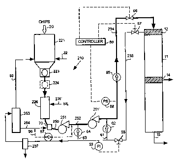
FIGURE 3 illustrates one preferred embodiment of a feed system 210
of the present invention that simplifies even further the prior art feeding
systems shown in FIGURES 1 and 2. In the preferred embodiment shown in
FIGURE 3, the high-pressure transfer device, component 27 of FIGURES 1
and 2, has been eliminated. Instead of transferring chips to the feeder 27 by
means of gravity in chute 26 of FIGURE 1 or via pump 51 in FIGURE 2, at
least one, preferably two, high-pressure slurry pumps 251, 251' are used to
transport the slurry to the inlet of the digester 11. The components in
FIGURE 3 which are essentially identical to those that appear in FIGURES 1
and 2 are identified by the same reference numbers. Those components
which are similar or which perform similar functions to those that appear in
FIGURES 1 and 2 have their reference numbers that appear in FIGURES 1
and 2 prefaced by the numeral "2".
Similar to the procedure in FIGURES 1 and 2, according to the present
invention, chips 20 are introduced to steaming vessel 221. The chips are
preferably introduced by means of a sealed horizontal conveyor as disclosed
in US patent no. 5,766,418, filed on September 13, 1996. Also, the steaming
CA 02266987 2003-05-12
21
vessel 221 is preferably a DIAMONDBACKO steaming vessel as described in
US patent 5,000,083 to which steam is added via one or more conduits 22.
The steaming vessel 221 typically includes conventional level monitoring and
controls as well as a pressure-relief device (not shown). Vessel 221
discharges steamed chips to metering device 223, which, as described above,
may be a pocketed rotor-type device such as a Chip Meter or a screw-type
device.
In one embodiment of this invention the metering device 223
discharges directly to conduit or chute 226. However, in an optional
embodiment, a pressure isolating device, such as a pocketed rotor-type
isolation device, shown in dotted line at 224, for example a conventional Low-
pressure Feeder, may be located between metering device 223 and chute
226. Though without the pressure-isolation device 224 the pressure in chute
226 is essentially atmospheric, with a pressure isolation device 224 the
pressure in chute 226 may range from 1 to 50 psig, but is preferably between
to 25 psig, and most preferably between about 10 to 20 psig. Cooking
liquor, as described above, is added to chute 226 (see line 226' in FIGURE 3)
so that a slurry of chips and liquor is produced in chute 226 having a
detectable level (not shown). The slurry in chute 226 is discharged via
conduit 250 to the inlet of pump 251. The introduction of slurry to the inlet
of
pump 251 is typically augmented by liquor flow from liquor tank 253 via
conduit 254 as described in US Patent No. 5,622,598.
Pump 251 is preferably a centrifugal high-pressure, helical screw,
slurry pump, such as a "hidrostal" pump supplied by Wemco of Salt Lake City,
Utah. The pump 251 may alternatively be a slurry pump supplied by the
Lawrence Company of Lawrence, Massachusetts. The pressure at the inlet to
pump 251 may vary from atmospheric to 50 psig depending upon whether a
pressure isolation device 224 is used.
In the preferred embodiment illustrated in FIGURE 3, the outlet of
pump 251 discharges to the inlet of pump 251'. Pump 251' is preferably the
same type of pump as pump 251 but with the same or a higher pressure
rating. If two pumps are used, the pressure produced in the outlet of pump
CA 02266987 2003-05-12
22
251' typically ranges from 150 to 400 psig (i.e., 345-920 feet of water,
gauge),
but is preferably between about 200 and 300 psig (i.e., 460-690 feet). If
necessary, the liquor in the slurry in conduit 252 may be augmented by liquor
from tank 253 via conduit 56 and liquid pump 57.
Though the embodiment illustrated in FIGURE 3 includes two pumps,
only one pump, or even three or more pumps, in series or parallel, may
alternatively be used. In these cases, the discharge pressure from the one
pump, or from the last pump, is preferably the same as the discharge
pressure from pump 251' above.
The pressurized, typically heated, slurry is discharged from pump 251'
to conduit 234. Conduit 234 passes the slurry to the inlet of continuous
digester 11. Excess liquor in the slurry is removed via screen 12 as is
conventional. The excess liquor is returned to the feed system 210 via
conduit 235, preferably to liquor tank 253 for use in slurrying in conduit 250
via conduit 254. The liquor in conduit 235 may be passed through a sand
separator 237 if desired. This sand separator 237 may be designed for
pressurized or unpressurized operation depending upon the mode of
operation desired.
Unlike the prior art systems employing a High-Pressure Feeder (27 in
FIGURES 1 and 2) which uses the pressure of the liquor returned via conduit
35 as an integral part of the method of slurrying from the High-Pressure
Feeder to the digester 11, it is not essential for the operation of the
present
invention that the pressurized recirculation 235 be returned to the inlet of
the
pumps 251, 251'. The energy available in the pressure of the flow in line 235
may be used wherever necessary in the pulp mill. However, in a preferred
embodiment, the present invention does utilize the pressure available in
conduit 235 to minimize the energy requirement of pumps 251 and 251' as
much as possible.
How the pressure in return line 235, typically about 150 to 400 psig is
used depends upon the mode of operation of the feed system 210. If conduit
or chute 226 is operated in an unpressurized - essentially atmospheric -
mode, the pressurized liquor returned in conduit 235 must be returned to
CA 02266987 2003-05-12
23
essentially atmospheric pressure before being introduced to conduit 250.
One means of doing this is to use a pressure control valve 58 and a pressure
indicator 59 in conduit 235. The opening in valve 58 is controlled such that a
predetermined reduced pressure exists in line 235 downstream of valve 58.
In addition, the liquor tank 253 may be
CA 02266987 1999-03-26
24
designed so that it acts as a "flash tank" so that the hot pressurized liquor
in conduit 235 is rapidly evaporated to produce a source of steam in
vessel 253. This steam can be used, among other places, in vessel 221
via conduit 60. However, instead, in a preferred embodiment, the
pressurized liquor in conduit 235 is used to augment the flow out of pump
251', for example via conduit 61 and pump 62. The pressure in conduit
235 may also be used to augment the flow between pumps 251 and 251'
in conduit 252 via conduit 63, with or without pump 64 (a check valvle may
in some cases be used in place of or in addition to each of pumps 62, 64).
By re-using some of the pressure available in line 235, some of the
energy requirements of pumps 251 and 251' may be reduced.
Also, the heat of the liquor in line 235 can also be passed in heat-
exchange-relationship with one or more other liquids in the pulp mill that
need to be heated.
The pressurizing and transferring of pumps 251 and 251' may
instead by effected by a conventional eductor, for example, an eductor
manufactured by Fox Valve Development Corporation. Or pumps 251,
251' may be used in conjunction with an eductor for increasing the
pressure in the inlet or outlet of the pumps. An eductor may also be used
as a means of introducing liquid to the chips. For example, an eductor
may be located in the outlet of or beneath vessel 226 and liquid first
introduced to the chips by means of this eductor. The eductor may
comprise a venturi-type orifice in one or more conduits 250, 252, and 234
into which a pressurized stream of liquid is introduced. This pressurized
liquid may be obtained from any available source but is preferably
obtained from conduit 235, upstream of valve 58. An exemplary eductor
is shown schematically at 70 in FIGURE 3.
CA 02266987 1999-03-26
The pumps 251 and 251' need not be centrifugal pumps but may
be any other form of slurry transfer device that can directly act on to
pressurize and transfer a slurry of chips and liquor from the outlet of
vessel 226 to the inlet of digester 11. For instance, a solids pump as
5 typically used in the mining industry may be used; for example, a double-
piston solids pump such as the KOS solids pump sold by Putzmeister, or
any other similar conventional pumping device may be used.
One function of the prior High-Pressure Feeder 27 of FIGURES 1
and 2 is to act as a shut-off valve to prevent possible escape of the
10 pressure in the equipment and transfer conduits, for example, conduits 34
and 35 of FIGURE 1, should any of the feed components malfunction or
fail. In the feed system 210 according to the present invention, alternative
means are provided to prevent such release of pressure due to
malfunction or failure. For example, FIGURE 3 illustrates a one-way
15 (check) valve 65 in conduit 234 to prevent pressurized flow from returning
to pump 251 or 251'. In addition, conventional automatic (e.g. solenoid
operated) isolation valves 66 and 67 are located in conduits 234 and 235,
respectively, to isolate the pressurized conduits 234, 235 from the rest of
the feed system 210. In one preferred mode of operation, a conventional
20 pressure switch 68 is located downstream of pump 251' in conduit 234.
The switch 68 is used to monitor the pressure in line 234 so that should
the pressure deviate from a predetermined value, the conventional
controller 69 will automatically isolate digester 11 from feed system 210
by automatically closing valves 66 and 67. These valves may also be
25 automatically closed when a flow direction sensor detects a reversal of
flow in conduit 234.
While the pressure release preventing means 65-69 described
above is preferred, other arrangements of valves, sensors, indicators,
CA 02266987 1999-03-26
26
alarms, or the like may comprise the pressure release preventing means
as long as such arrangements adequately perform the function of
preventing significant depressurization of the digester 11.
While the system 210 is preferably used with a continuous digester
11, it also may be used with other vertical superatmospheric (typically a
pressure of at least about 10 bar gauge) treatment vessels having a top
inlet, such as an impregnation vessel or a batch digester.
FIGURE 4 illustrates a further embodiment of this invention i~r
which the concept of transferring chips is extended from the feed system
of a digester to the Woodyard of a pulp mill. FIGURE 4 illustrates a
system 510 for feeding comminuted cellulosic fibrous material to a pulping
process. It consists of a subsystem 410 for introducing chips from the
Woodyard to system 510 and a subsystem 310 for treating and feeding
chips to digester 11. Subsystem 310 is essentially identical to the system
210 shown in FIGURE 3.
Again, the components in FIGURE 4 which are identical to those
that appear in FIGURES 1-3 are identified by the same reference
numbers. Those components which are similar or which perform similar
functions to those that appear in FIGURE 1-3 have their reference
numbers that appear in FIGURE 1 prefaced by the numeral "3".
The Woodyards of conventional pulp mills receive their wood
supply in various forms as described above. Typically, the wood, or other
comminuted cellulosic fibrous material, is converted to chip like form and
stored either in open chip piles or in chip storage silos. In FIGURE 4 the
chip supply is shown as chip pile 80. In a preferred embodiment of this
invention the chips from pile 80 or some other storage vessel are
conveyed by conventional means, e.g., a conveyor or front-end loader
(not shown), and introduced 20 to vessel 81. This vessel may be a
CA 02266987 2003-05-12
27
DIAMONDBACK vessel or any other conventional storage vessel. Vessel 81
may be operated at superatmospheric pressure, for example at 0.1 to 5 bar.
If the vessel is operated at superatmospheric pressure, some form of
pressure isolation device (not shown) may be located at the inlet of the
vessel
to prevent the release of pressure. This device may be a star-type isolation
device, such as a Low-pressure Feeder or Air-lock Feeder as sold by
Ahlstrom Machinery, or a screw-type feeder having a sealing capacity as
described in US patent no. 5,766,418.
Liquid, for example fresh water, steam, liquids containing cooking
chemicals is introduced to vessel 81 via one or more conduits 82 to produce a
slurry of liquid and chips and to provide a detectable liquid level in vessel
81.
Means for monitoring and controlling the level of the liquid, and the level of
the
chips, in vessel 81 may be provided. This liquid may be a heated liquid, for
example, hot water or steam, having a temperature of between 50 and
100°C.
If the vessel is a pressurized vessel, liquid temperatures of over
100°C may
be used. Preferably, though not essentially, this liquid may contain at least
some active pulping chemical, for example, sodium hydroxide (NaOH),
sodium sulfide (Na2S), polysulfide, anthraquinone or their equivalents or
derivatives or surfactants, enzymes or chelants, or combinations thereof.
From vessel 81, the slurry is discharged to the inlet of slurry pump 85
via conduit 84. The discharge from vessel 81 may be aided by a discharge
device 83 (probably not necessary if a DIAMONDBACK~ discharge is used).
The flow of slurry in conduit 84 may also be aided by the addition of liquid
via
conduit 82'. The conduit 82' may be the only mechanism for introducing
liquid, so that a liquid level is present in conduit 84 or not in vessel 81.
Pump
85 may be any type of slurry pump discussed above, for example, a Wemco
or Lawrence pump or their equivalents, any other type of solids or slurry
transfer device. Though only one pump 85 is shown, more than one pump or
similar devices may be used to transfer the slurry via conduit 86 to vessel
321. The slurry transfer via conduit 86 may include one or more storage or
surge tanks (not shown). Preferably, the one or more pumps 85 include at
CA 02266987 2003-05-12
28
least one deice having de-gassing capability so that undesirable air or other
gases may be removed from the slurry.
The slurry discharged from pump 85 is transferred via conduit 86 to
subsystem 310. Subsystem 310 may be located adjacent subsystem 410,
that is, within about 30 feed of subsystem 410, or may be spaced an
appreciable distance from subsystem 410, for example on-half mile or more
away, depending upon the layout of the pulp mill. Hence, conduit 86 is
broken to indicate an undetermined distance between subsystem 410 and
subsystem 310.
The pressure in conduit 86 is dependent upon the number of pumps
and other transfer devices used and the height and distance that the slurry
must be transferred. The pressure in conduit 86 may vary from about 5 psig
to over 500 psig.
Also, during transfer, the chips may be exposed to some form of
treatment, for example, de-aeration or impregnation with a liquid, preferably
a
liquid containing pulping chemicals, such as those described above. The
slurry may also be exposed to at least one pressure fluctuation during
transfer, such that the pressure of the slurry is varied from a first pressure
to a
second, higher pressure, and then to a third pressure which is lower than the
second pressure. As described in US patents 4,057,461 and 4,743,338
varying the pressure of a slurry of chips and liquor improves the impregnation
of the chips with the liquor. This pressure pulsation may be achieved via
varying the outlet pressure of a
CA 02266987 1999-03-26
29
set of transfer devices in series, or by controlled depressurization of the
slurry between pumping.
The slurry in conduit 86 is introduced to the inlet of vessel 321.
Though the vessel shown is a treatment, i.e., steaming, vessel, it may
also be a storage vessel, an impregnation vessel, or even a digester.
Since the transfer in conduit 86 typically requires that at least some
excess liquid, that is not needed during treatment or storage, some form
of de-watering device 87 may be located between the transfer devise and
the treatment vessel. One preferred dewatering device is a Top
Separator, as sold by Ahlstrom Machinery. This Top Separator may be a
standard type or an "inverted" Top Separator. This device may be an
external stand-alone-type unit or one that is mounted directly onto the
treatment vessel, as shown. Preferably, the liquid removed from the
slurry by means of de-watering device 87 is returned to vessel 82 or to
the inlet of the pump, or pumps, 85 via conduit 88 to aid in slurrying the
chips. This liquid removed via device 87 may also be used where ever
needed in the pulp mill. This liquid in conduit 88 may be heated or cooled
as desired in a heat exchanger 90 and may be pressurized using one or
more conventional centrifugal liquid pumps, 89. The liquid in conduit 88
may be introduced to vessel 81 via conduit 82 and to conduit 84 via
conduit 82'.
The treatment vessel 321 shown is a steaming vessel similar to
vessel 221 shown in FIGURE 3, for example a DIAMONDBACK steaming
vessel. The feed system 310 is otherwise similar to the system 210
shown in FIGURE 3. For example, chip feeding system 410, feeds
digester feed system 310, which feeds digester 11. Note that system
310 of FIGURE 4 is simply one subsystem in the over-all system which
CA 02266987 1999-03-26
feeds chips from the chip pile 80 to the digester 11. This system may
include one or more subsystems 310 for feeding to digester 11.
FIGURE 5 illustrates a further embodiment 610 of this invention
that is an extension of the system 510 shown in FIGURE 4. The system
5 610 is a combination of three subsystems 710, 810 and 910. Subsystem
710 is similar to the system 410 of FIGURE 4. Items in FIGURE 5 that are
essentially identical to those found in FIGURES 1 through 4 are identified
by the same numbers.
Wood chips 20, or some other comminuted cellulosic fibrous
10 material, from chip pile 80 are introduced with or without pressure
isolation to vessel 81. The chips in vessel 81 may be treated with a gas,
such as steam or hydrogen sulfide, or a liquid, such as water or a liquid
containing cooking chemical, introduced by way of one or more conduits
82. Vessel 81 may be any type of vessel, but is preferably a
15 DIAMONDBACK~ bin; as described above. The treated chips are
discharged from vessel 81 into conduit 84. Though any type of
discharging mechanism can be used, the discharge of chips from vessel
81 is preferably performed without the aid of mechanical agitation or
vibration, as is characteristic of DIAMONDBACK~ chips bins. Conduit
20 84 may be any type of pipe or chute but is preferably a curved Chip Tube
as described above.
Conduit 84 introduces the chips to the inlet of slurry pump 85,
which may be of the type supplied by Wemco or Lawrence, as described
above. Typically, slurrying liquid is preferably first introduced to the chips
25 in conduit 84, for example, using the conduit 82', to produce a level of
liquid in vessel 81 or conduit 84. The liquid introduced via conduit 82',
may be water or a liquid containing treatment chemicals such as kraft
liquors, with or without strength or yield enhancing additives. Make-up
CA 02266987 1999-03-26
31
liquor, for example, liquor containing these chemicals, is typically added
via conduit 782.
The slurry in conduit 86 is introduced to subsystem 810 via liquor
separating device 887, which is similar in operation to device 87 shown in
FIGURE 4. The liquid removed via separator 887 can be returned to
subsystem 710 via conduit 88 or can be used elsewhere in the pulp mill
via conduit 888. If returned to subsystem 710 via conduit 88 the liquor
may be augmented with additional liquid or chemical via conduit 788,
heated via indirect heat exchanger 90 via conduit 790 and pressurized by
pump 89 prior to being re-introduced to vessel 81 via conduit 82 or to
conduit 84 via conduit 82'. Subsystem 710 may also include a liquor
storage tank similar to tank 353 shown in FIGURE 4. Thus by the use of
heater 90 and chemical addition 782 or 788, the slurry of material
transferred from subsystem 710 to subsystem 810 via conduit 86 may be
heated to any desirable temperature while being treated with chemicals.
For example, if the slurry in conduit 86 is heated to about 90°C
or above
in the presence of alkali or sulfide, some pretreatment of the will occur
during the retention time in conduit 86 prior to introduction of the slurry
into subsystem 810. Of course, lower temperatures and other chemicals
may also be used in conduit 86.
The chips retained by separator 887 are passed to vessel 821.
Vessel 821 may be a vessel similar to vessel 81, but is preferably a tall
cylindrical vessel, for example, 20 to 50 feet tall, in which a liquid level
823 is maintained. A gas space 824 may be maintained above level 823.
Vessel 821 may be maintained at atmospheric pressure or at super-
atmospheric pressure, for example, at 0.2 to 10 bar gauge pressure (e.g.
about 5 bar), depending on the treatment performed in vessel 821. The
temperature in vessel 821 may vary from 50 to 300°C, but is typically
CA 02266987 1999-03-26
32
between about 50 and 150°C. Liquid may be introduced to vessel 821 via
one or more conduits 822 or 860. This liquid may contain cooking
chemicals or additives as discussed above. These cooking chemicals or
additives may be the same as those introduced in subsystem 710 or they
may be different. For example, kraft cooking liquor containing a high
concentration of sulfide ion or sulfidity may be introduced to subsystem
710 and kraft cooking chemical containing a lower concentration of sulfide
ion or sulfidity may be introduce to the chips in subsystem 810. In
another example, a polysulfide-type additive may be introduced to the
chips in subsystem 710 and an anthraquinone-type additive may be
introduced in subsystem 810.
The pressure within the vessel 821 may be monitored and
controlled via pressure indicator and controller 825. Excess pressure
may be released via conduit 826, for example, to a conventional non-
condensable gas (NCG) treatment system or to vessel 81 for
pretreatment. In addition, the pressure controller 825 can be used to
regulate the pressure in vessel 821 to vary the pressure to effect pressure
pulsation impregnation as described in US patents 4,057,461 and
4,743,338.
The slurry is discharged from vessel 821 to conduit 850. This
discharge may be effected without agitation or vibration as in a
DIAMONDBACK chip bin, or it may be effected by agitation or vibration as
is conventional. Conduit 850 introduces the slurry to the inlet of pump
851, which may be similar to pump 85, but typically will have a higher
pressure rating. Additional liquid may be introduced to conduit 850 via
conduit 854 to aid in introducing the slurry to the pump 851. The slurry
discharged from pump 851 is passed to subsystem 910 via conduit 886.
CA 02266987 1999-03-26
33
The slurry in conduit 886 is introduced to subsystem 910 using the
liquor separating device 987. The separator 987 is similar to devices 887
and 87 (of FIGURE 4). The liquor removed from device 987 may be
returned by conduit 911 to subsystem 810 or may be used elsewhere in
the pulp mill via conduit 988. If returned to subsystem 810 via conduit
911, the liquor may be augmented with additional liquid or chemical via
conduit 912, heated via indirect heat exchanger 890 via conduit 891 and
pressurized by pump 889 prior to being re-introduced to vessel 821 ~uia
conduit 822 or 860 to conduit 850 via conduit 854. The liquor in conduit
911 may also be introduced to subsystem 710, for example, via a
common connection with conduit 88 or 82. Subsystem 810 may also
include a liquor storage tank similar to tank 353 shown in FIGURE 4.
Thus by using heater 890 and chemical addition 912, the slurry of
material transferred from subsystem 810 to subsystem 910 via conduit
886 may be heated to any desirable temperature while being treated with
chemicals. For example, if the slurry in conduit 886 is heated to about
90°C or above in the presence of alkali or sulfide, some pretreatment
of
the material will occur during the retention time in conduit 886 prior to
introduction of the slurry into subsystem 910. Of course, lower
temperatures and other chemicals may also be used in conduit 886
The chips retained by separator 987 are passed to vessel 921,
which may be a vessel similar to vessels 81, or a tall vessel similar to
vessel 821, or a vessel similar to vessel 321 of FIGURE 4. Vessel 921
may be maintained at atmospheric pressure, or at super-atmospheric
pressure (for example, at 0.2 to 10 bar gauge, preferably 0.5 to 5 bar
gauge pressure] depending on the treatment performed in vessel 921.
The temperature in vessel 921 may vary from 50 to 300°C, but is
typically
between about 50 and 150°C, preferably between about 80 and
120°C.
CA 02266987 1999-03-26
34
Liquid may be introduced to vessel 921 via one or more conduits 922 or
960. The introduced liquid rnay contain cooking chemicals or additives as
discussed above. These cooking chemicals or additives may be the
same as those introduced in subsystem 710 or 810 or they may be
different. For example, kraft cooking liquor containing a high
concentration of sulfide ion or sulfidity may be introduced to subsystem
810 and kraft cooking chemical containing a lower concentration of sulfide
ion or sulfidity may be introduced to the chips in subsystem 910. Ini
another example, a polysulfide-type additive may be introduced to the
chips in subsystem 710 and an anthraquinone-type additive may be
introduced in subsystem 810, and kraft white liquor may be introduced to
the chips in subsystem 910. Each or these liquors can be isolated from
each other by the liquor separators 887 and 987.
The slurry is discharged from vessel 921 to conduit 950. This
discharge may be effected without agitation or vibration using a discharge
as in a DIAMONDBACK~ chips bin, or it may be aided by agitation or
vibration as is conventional. Conduit 950 introduces the slurry to the inlet
of pump 951, which may be similar to pumps 85 and 851, but typically will
have a higher pressure rating. Additional liquid may be introduced to
conduit 950 via conduit 960 to aid in introducing the slurry to the pump
951. The slurry discharged from pump 951 is passed to further treatment
via conduit 886, for example, to a digester ( that is, a continuous or batch
digester), or to further treatment in a subsystem similar to subsystems
810 or 910, or subsystem 310 of FIGURE 4. However, the treatment
effected in subsystems 710, 810 and 910 may be sufficient to produce an
essentially fully-cooked pulp slurry in conduit 950 such that no further
"pulping" need be performed. The pulp in conduit 950 may be passed
directly to washing and/or bleaching.
CA 02266987 1999-03-26
As in subsystems 310, 810, and 910, excess liquor may be
returned to subsystem 910 via conduit 913. The liquor may be augmented
with additional liquid or chemical via conduit 914, heated via indirect heat
exchanger 990 via conduit 991 and pressurized by pump 989 prior to
5 being re-introduced to vessel 921 via conduit 922 or to conduit 950 via
conduit 960. The liquor in conduit 913 may also be introduced to
subsystem 710 or 810, for example, via a common connection with
conduit 88 or 82 (not shown) or a common connection with conduits~911
or 822, or similar conduits. Subsystem 910 may also include a liquor
10 storage tank similar to tank 353 shown in FIGURE 4.
Thus, using heater 990 and chemical addition 914, the slurry of
material transferred from subsystem 910 to the subsequent subsystem or
digester via conduit 986 may be heated to any desirable temperature
while being treated with chemicals. For example, if the slurry in conduit
15 986 is heated to about 90°C or above in the presence of alkali or
sulfide,
some pretreatment of the chips will occur during the retention time in
conduit 986 prior to introduction of the slurry into the subsequent
treatment device, for example to digester 11 of FIGURES 1 and 2. Of
course, lower or higher temperatures and other chemicals may also be
20 used in conduit 986.
Also, though indirect heat exchangers 90, 890, and 990 may each
be supplied by their own separate source of heat, for example, separate
sources of steam or hot water or hot effluent that would normally be
discharged, heat exchangers 90, 890 and 990 may also be supplied with
25 a common source of heat 915. The source of heat 915 may be, for
example, hot effluent or steam (low, medium or high pressure steam), and
may be introduced to heat exchanger 990 and the residual heat
transferred to heat exchanger 890 via conduit 992. The residual heat
CA 02266987 1999-03-26
36
from heat exchanger 890 may be passed to heat exchanger 90 via
conduit 892. Any residual heat remaining in conduit 92 may be used as
needed in systems 710, 810 or 910 or elsewhere in the mill, or it may be
discarded. For example, the liquid in conduit 92, and any residual heat it
may contain, may be introduced to vessel 81 or 821 via conduits 82 or
822 to recover and re-use as much of the available energy as possible.
Using a system 610 as shown in FIGURE 5, a counter-current flow
of treatment liquids can be established between each subsystem. F;or
example, the liquid from upstream treatment can be returned to
subsystem 910 via conduit 913; the liquid from subsystem 910 can be
returned to subsystem 810 via conduit 911; and the liquid from subsystem
810 can be returned to subsystem 710 via conduit 88. In addition some
or all of these liquors can be removed and used elsewhere via conduits
888 and 988.
The chemical addition at 788, 912 , and 914 is preferably sodium
hydroxide, sodium sulfide; polysulfide, anthraquinone or their equivalents
or derivatives; surfactants, enzymes, or chelants; or combinations thereof.
For example, different treatment chemicals could be added at each of
788, 912, and 914, so that different treatments take place in each of the
sections 710, 810, and 910. For example, polysulfide may be added at
788, anthraquinone at 912, and chelants and enzymes at 914. The
conduits at 788, 912, 914 need not be provided where illustrated in
FIGURE 5, but may be provided at any convenient location which
facilitates impregnation, or other pretreatment, simultaneously with
transport. For example, lines 788, 912, 914 may be added to the lines
790, 891, 991 before the heater exchangers 90, 890, 990, respectively.
FIGURE 6 schematically illustrates other apparatus according to
the invention, for practicing a method according to the invention. Utilizing
CA 02266987 1999-03-26
37
the system of FIGURE 6 a slurry of comminuted cellulosic fibrous material
(typically at a consistency of about 5-20%) is transported within a pulp mill
at any locations within a fiber line, such as from the wood yard to a
digester, with intermittent booster pumps in series. Each pump is
associated with a station (treatment vessel) and a solidsl liquid separator
is associated with each station (typically a conventional solid/liquid
separator at the top of the station), to isolate liquor streams or
circulations. Impregnation, or other pretreatment, is performed
simultaneously during transit of the material, in the circulation fines (that
is
from ane pump to its associated station), and the lines can be made very
long (e.g. more than 100 yards, up to about a half a mile) to facilitate that
pretreatment and impregnation. Preferably heat exchangers are utilitzed
on the return lines, and degassing may be provided at one, more than
one, or all of the transfer stations. Also, an eductor (ejector) can be used
in place a flash tank and/or control valves through which liquor is removed
and pressure reduced. Further, pressurized pulsation action may be
associated with the configuration of pumps and stations, the pumps
pressurizing the slurry to at least 5 bar (typically at least about 10 bar).
Also, a wide variety of treatment chemicals may be utilized preferably
added upstream of the pumps, including sodium hydroxide, sodium
sulfide; polysulfide, anthraquinone or their equivalents or derivatives;
surfactants, enzymes, or chelants; or combinations thereof.
The chip slurry 1000 is formed in any conventional manner
(including by heat steam slurrying), and first, second and third booster
pumps 1001, 1002, and 1003 are connected in series. The pumps 1001-
1003 are associated with stations (vessels) 1004, 1005, 1006,
respectively. Preferably each of the stations 1004-1006 has a liquid/solid
separator associated therewith. In the embodiment illustrated in FIGURE
CA 02266987 1999-03-26
38
6 separators 1007, 1008, 1009 are shown mounted at the top of each of
the stations (treatment vessels) 1004-1006, although the separator could
be at another location, including the bottom.
Preferably chemical is added to the slurry at a number of different
locations in the system, such as upstream at each of the pumps 1001-
1003. This is schematically illustrated by chemical addition at points
1010, 1011, and 1012 in FIGURE 6. The same, or different, chemicals
can be added at each of 1010-1012. Preferably at least some of the
chemical includes sodium hydroxide, sodium sulfide; polysulfide,
anthraquinone or their equivalents or derivatives; surfactants, enzymes,
or chelants; or combinations thereof. In the embodiment actually
illustrated in FIGURE 6, the chemical addition 1012 includes AQ laden
white liquor (e.g. vessel 1006 is a continuous digester).
Instead of establishing circulation lines such as illustrated in
FIGURE 5, circulation is provided in the FIGURE 6 embodiment, in the
preferred form, so as to cause pseudo counter-current flow of the
comminuted cellulosic fibrous material and liquid. While FIGURE 6
illustrates three stations, any number of stations may be provided. In the
embodiment in FIGURE 6, the liquid removed from the separator 1007 in
line 1013, is used elsewhere in the mill, or treated for reuse. The liquid
removed from separator 1008 passes in line 1014 to a point upstream of
the pump 1001 (e.g. it is diverted by the valve 1015 either to the slurrying
station 1000, or to the infeed to the pump 1001) while liquid separated by
the third separator 1009 is circulated in line 1016 to upstream of the pump
1002, e.g. diverted by the valve 1017 to the first station 1004, and/or to
just upstream of the pump 1002. Fresh liquor, from source 1012, is
added to the bottom of the vessel 1005, or the intake of the pump 1003.
CA 02266987 1999-03-26
39
In the return lines 1014, 1016, conventional indirect heat
exchangers 1018, 1019 may be provided which change the temperature
of the liquid therein by at least 5°C. In the embodiment illustrated,
the
liquor is heated, but in some circumstances the liquid could be cooled
instead of heated. A indirect heat exchanger 1020 may be also be
associated with the chemical addition 1012.
Liquor can be passed from the third station 1006 (which may be a
digester -- e.g. black liquor) through a conventional eductor (ejector
1022, rather than a flash tank and/or control valves. Each of the pumps
1001-1003 preferably pressurizes the slurry to a pressure of at least 5 bar
(typically at least about 10 bar).
Degassing may also be associated with one, more than one, or all
of the stations 1004. This is schematically illusrated by the gas removal
lines 1023-1025 in FIGURE 6. Degassing may be accomplished using
any conventional degassing equipment, associated with the separator
1007-1009, the inlet line, or the like.
In the broadest aspect of this invention, a system and method are
provided for the multistage transport and treatment of comminuted
cellulosic fibrous material with the economical recovery and re-use of
energy, including thermal energy.
While the invention has been described in connection with what is
presently considered to be the most practical and preferred embodiment,
it is to be understood that the invention is not to be limited to the
disclosed embodiment, but on the contrary, is intended to cover various
modifications and equivalent arrangements included within the spirit and
scope of the appended claims.