Language selection

Search

Patent 2267359 Summary

Third-party information liability

Some of the information on this Web page has been provided by external sources. The Government of Canada is not responsible for the accuracy, reliability or currency of the information supplied by external sources. Users wishing to rely upon this information should consult directly with the source of the information. Content provided by external sources is not subject to official languages, privacy and accessibility requirements.

Claims and Abstract availability

Any discrepancies in the text and image of the Claims and Abstract are due to differing posting times. Text of the Claims and Abstract are posted:

  • At the time the application is open to public inspection;
  • At the time of issue of the patent (grant).
(12) Patent: (11) CA 2267359
(54) English Title: INSECT CATCHING DEVICE
(54) French Title: DISPOSITIF DE CAPTURE D'INSECTES
Status: Term Expired - Post Grant Beyond Limit
Bibliographic Data
(51) International Patent Classification (IPC):
  • A01M 01/04 (2006.01)
  • A01M 01/14 (2006.01)
(72) Inventors :
  • GREENING, JOHN LLEWELLYN (United Kingdom)
(73) Owners :
  • PEST WEST ELECTRONICS LIMITED
(71) Applicants :
  • PEST WEST ELECTRONICS LIMITED (United Kingdom)
(74) Agent: NORMAN M. CAMERONCAMERON, NORMAN M.
(74) Associate agent:
(45) Issued: 2005-03-15
(86) PCT Filing Date: 1997-09-11
(87) Open to Public Inspection: 1998-03-19
Examination requested: 2002-05-09
Availability of licence: N/A
Dedicated to the Public: N/A
(25) Language of filing: English

Patent Cooperation Treaty (PCT): Yes
(86) PCT Filing Number: PCT/GB1997/002442
(87) International Publication Number: GB1997002442
(85) National Entry: 1999-03-11

(30) Application Priority Data:
Application No. Country/Territory Date
9619185.3 (United Kingdom) 1996-09-13

Abstracts

English Abstract


An insect catching device comprises (a) a source of radiation having a
wavelength that is suitable for attracting insects, (b) a quantity,
of an adhesive material provided on a surface of the device on which insects
attracted to the device by the radiation source impinge, and
(c) a shield for restricting direct exposure of the adhesive material to
radiation from the radiation source.


French Abstract

Dispositif de capture d'insectes qui comporte (a) une source de rayonnement dont la longueur d'onde est appropriée pour attirer des insectes, (b) une quantité d'une matière adhésive placée sur une surface du dispositif que heurtent des insectes attirés vers le dispositif par la source de rayonnement et (c) un écran destiné à limiter l'exposition directe de la matière adhésive au rayonnement produit par la source.

Claims

Note: Claims are shown in the official language in which they were submitted.

-7-
CLAIMS
1. An insect catching device which comprises:
(a) a source of radiation having a wavelength that is
suitable for attracting insects, in the form of an
elongate tube,
(b) a quantity of an adhesive material provided on a
surface of the device on which insects attracted to the
device by the radiation source impinge, and
(c) a shield which is concave when viewed from one
end which is provided as a coating on the tubular
radiation source, for restricting direct exposure of
the adhesive material on the said surface to radiation
from the radiation source.
2. A device as claimed in claim 1, in which the radiation
source comprises at least one elongate tubular body, and in
which this shield extends along at least a substantial part
of the length of the body.
3. A device as claimed in claim 1 or claim 2, in which the
shield comprises an element that is located between the
radiation source and the adhesive coated surface.
4. A device as claimed in claim 3, in which the element is
self supporting, so that it is sufficiently rigid to be able
to retain a suitable configuration to act as a shield even
when supported at only one or two points along its length.
5. A device as claimed in any one of claims 1 to 4, in
which the surface of the shield that faces towards the
radiation source is reflective.

Description

Note: Descriptions are shown in the official language in which they were submitted.


CA 02267359 1999-03-11
WO 98/10643 PCT/GB97/02442
-1-
INSECT CATCHING DEVICE
This invention relates to an insect catching device. The
invention is concerned in particular with a device of the kind
which comprises a source of radiation having a wavelength
suitable for attracting insects to the device, and a quantity
of an adhesive material provided on the surface of the device
of which insects attracted to the device by the radiation
source impinge.
Insect catching devices which use a radiation source to attract
insects are known. The radiation will often have a wavelength
in the ultraviolet region: suitable radiation sources will
often emit radiation having a blue appearance. Radiation
sources emitting radiation with a blue-green appearance are
also known to be suitable for certain applications.
Insects attracted to such a device by a radiation source can be
retained in the device by means of an adhesive material
provided as a coating on a surface of the device, generally
behind the radiation source. Such a device will therefore
often comprise one or more tube elements from which ultra
violet radiation is emitted, and an adhesive coated back plate .
Many adhesive materials which are suitable for use in such
insect catching devices can be degraded when exposed to
ultraviolet radiation. This leads to a reduction in the
capability of such devices to retain insects within them.
Frequent replacement of the adhesive material, generally on a
pre-coated backplate, is required. '
The present invention provides an insect catching device which
includes a shield to restrict direct exposure of adhesive
material in an insect catching device to insect attracting
radiation.

' CA 02267359 1999-03-11 ,
WO 98/10643 PCT/GB97/02442
-2-
Accordingly, in. one aspect the invention provides an insect
catching device which comprises:
(a) a source of radiation having a wavelength that is
suitable for attracting insects,
(b) a quantity of an adhesive material provided on a
surface of the device on which insects attracted to the
device by the radiation source impinge, and
(c) a shield for restricting direct exposure of the
adhesive material on the said surface to radiation from
the radiation source.
The device of the present invention has been found to be
capable of attracting insects to it as efficiently as devices
which do not include a shield. Moreover, the presence of a
shield has been found to prolong the period in which the
adhesive material provided to collect insects is effective.
This therefore results in greater convenience in operation of
the device of the invention, and reduced operating cost.
Moreover, a shield can be used to enhance the lifetime of an
adhesive insect collection material while also allowing the
radiation source (such as a fluorescent tube) to be positioned
close to the adhesive material to maximise insect attraction.
The radiation source used in the device of the invention will
generally be provided by a fluorescent tube element. Such
elements can emit radiation on a suitable'wavelength .for
attracting insects. Such radiation would generally be
ultraviolet radiation. Suitable ultraviolet radiation might ,
have, for example, a purple appearance or a blue-green
appearance. The radiation source can be provided as an ,
elongate tubular body. The tubular body can be straight, for
example to extend between connecting terminals at opposite ends
thereof. The radiation source can alternatively have its

CA 02267359 1999-03-11
WO 98/10643 PCT/GB97102442
-3-
connection terminals provided adjacent to one another at one
end thereof, the radiation source having a generally cu=ved
configuration.
The shield will preferably extend along substantially the
entire length of the body of the radiation source. For
example, when the radiation source provides an elongate,
generally straight, tubular body, the shield will extend along
substantially the entire length of the tubular body.
The shield can be provided as a coating on the radiation
source. For example, when the radiation source comprises a
generally tubular body, that body can be provided with a
coating, over at least a substantial part of the portion of the
body which faces the adhesive coated surface of the device when
in use.
A shield that is separate from the radiation source can also be
used. The shield will then comprise an element that is located
between the radiation source and the adhesive coated surface of
the device. The element can be self supporting, so that it is
sufficiently rigid to be able to retain a suitable
configuration to act as a shield even when supported at only
one, two or more points along its length. A suitable shield
can be provided by an appropriately formed sheet of metal or
other material (for example polymeric or ceramic material)
having suitable shield properties.
Preferably, the shield will be constructed so that she
intensity of radiation that impinges on the'adhesive co~~ed
surface of the device is not more than about 800 of the level
in the absence of the shield. Preferably, the intensity is rot
more than about 650, especially not more than about 45%, nor
example, not more than about 25% of that figure.
The shield can restrict direct exposure of the adhesive
material to radiation from a radiation source by, for example,

CA 02267359 1999-03-11
WO 98/10643 PCT/GB97/02442
-4-
absorption of the radiation or reflection. Ref,lec~ion of the
radiation will be particularly appropriate for many
applications (although non-'reflective shields can perform
satisfactorily). This can be achieved by use of.a reflective
material for the surface of the shield which faces the
radiation source. For example, when the shield is provided by
a coating on the radiation source, the coating can be a
metallised coating. When the shield is provided as an element
located between the radiation source and the adhesive coated
surface, a reflecting surface can be provided by polishing, or
by an appropriate surface coating.
The adhesive material can be provided on a surface of the
housing of the device. Preferably, however, the adhesive
coating is provided on a sheet element which can be loaded into
the device for use, and removed when its fly collecting
properties have deteriorated, for example due to deterioration
of the adhesive properties of the adhesive material, or due to
collection of a large number of insects. The element can be
received in appropriate formations such as grooves or slots in
the device housing.
Suitable adhesive materials for use in the device of the
invention are known, and are available widely on pre-coated
sheets for insect collection.
The present invention will now be described, by way of example
only, with reference to the accompanying drawings, in which:
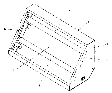
Figure 1 is an isometric view of an'insect catching
device according to the present invention.
Figure 2 is a section elevation through the device of the
invention shown in Figure 1. ,
Referring to the drawings, an insect catching device 2
comprises a housing 4. The housing is open over a front face,

CA 02267359 1999-03-11
WO 98/10643 PCT/GB97/02442
-5-
which is covered by a grill, which is not shown in the drawi-_as
for the sake of clarity.
A plurality of radiation emitting fluorescent tubes 8 are
located in the housing. The tubes are straight, extending from
one side of the housing to the other.
The rear internal surface 10 of the housing is covered by a
removable sheet element 12, having an adhesive material over
its exposed surface facing towards the radiation source tubes
and the grill. The adhesive coated sheet can be slid into the
housing through a slot in the top face of the housing, received
in appropriate vertical grooves l4 at each end of the housing.
Separate shields 16 are provided between each of the
fluorescent tubes and the adhesive coated surface. The shields
are formed from aluminium. The surface of the shields which
faces towards the tubes can be polished so that radiation from
the tubes is reflected by the shield away from the adhesive
coated surface. The shields are concave when viewed along the
axis of the radiation source tubes. The shields restrict
exposure of the adhesive coated surface to radiation from the
radiation source tubes.
In use, insects are attracted to the device by radiation from
the radiation source tubes. Such insects pass the tubes and
impinge on the adhesive coated surface. They are retained on
the surface by the adhesive.
The shields provided between the radiation source tubes and.Ln2
adhesive.coated surface restrict exposure of the surface ~o
radiation. This restricts degradation of the adhesive material
which would otherwise result from its exposure to ultraviolet
radiation.

Representative Drawing
A single figure which represents the drawing illustrating the invention.
Administrative Status

2024-08-01:As part of the Next Generation Patents (NGP) transition, the Canadian Patents Database (CPD) now contains a more detailed Event History, which replicates the Event Log of our new back-office solution.

Please note that "Inactive:" events refers to events no longer in use in our new back-office solution.

For a clearer understanding of the status of the application/patent presented on this page, the site Disclaimer , as well as the definitions for Patent , Event History , Maintenance Fee  and Payment History  should be consulted.

Event History

Description Date
Inactive: Expired (new Act pat) 2017-09-11
Inactive: Payment - Insufficient fee 2015-09-11
Maintenance Request Received 2015-08-31
Inactive: Payment - Insufficient fee 2013-08-20
Maintenance Request Received 2013-08-14
Inactive: Payment - Insufficient fee 2012-12-07
Inactive: Late MF processed 2012-11-19
Maintenance Request Received 2012-11-19
Inactive: Late MF processed 2012-09-20
Letter Sent 2012-09-11
Grant by Issuance 2005-03-15
Inactive: Cover page published 2005-03-14
Inactive: Office letter 2005-01-05
Inactive: Delete abandonment 2005-01-04
Inactive: Final fee received 2004-10-19
Pre-grant 2004-10-19
Deemed Abandoned - Failure to Respond to Maintenance Fee Notice 2004-09-13
Notice of Allowance is Issued 2004-08-26
Letter Sent 2004-08-26
Inactive: Approved for allowance (AFA) 2004-08-06
Letter Sent 2002-06-26
Request for Examination Requirements Determined Compliant 2002-05-09
All Requirements for Examination Determined Compliant 2002-05-09
Request for Examination Received 2002-05-09
Letter Sent 2000-10-24
Reinstatement Requirements Deemed Compliant for All Abandonment Reasons 2000-10-04
Deemed Abandoned - Failure to Respond to Maintenance Fee Notice 2000-09-11
Letter Sent 1999-06-18
Inactive: Cover page published 1999-06-02
Inactive: Single transfer 1999-05-18
Inactive: First IPC assigned 1999-05-17
Inactive: IPC assigned 1999-05-17
Inactive: Courtesy letter - Evidence 1999-05-11
Inactive: Notice - National entry - No RFE 1999-05-05
Inactive: Inventor deleted 1999-05-05
Application Received - PCT 1999-04-30
Small Entity Declaration Determined Compliant 1999-03-11
Application Published (Open to Public Inspection) 1998-03-19

Abandonment History

Abandonment Date Reason Reinstatement Date
2004-09-13
2000-09-11

Maintenance Fee

The last payment was received on 2004-08-24

Note : If the full payment has not been received on or before the date indicated, a further fee may be required which may be one of the following

  • the reinstatement fee;
  • the late payment fee; or
  • additional fee to reverse deemed expiry.

Patent fees are adjusted on the 1st of January every year. The amounts above are the current amounts if received by December 31 of the current year.
Please refer to the CIPO Patent Fees web page to see all current fee amounts.

Fee History

Fee Type Anniversary Year Due Date Paid Date
Basic national fee - small 1999-03-11
Registration of a document 1999-05-18
MF (application, 2nd anniv.) - small 02 1999-09-13 1999-09-07
MF (application, 3rd anniv.) - small 03 2000-09-11 2000-10-04
Reinstatement 2000-10-04
MF (application, 4th anniv.) - small 04 2001-09-11 2001-09-10
Request for examination - small 2002-05-09
MF (application, 5th anniv.) - small 05 2002-09-11 2002-08-12
MF (application, 6th anniv.) - small 06 2003-09-11 2003-08-13
MF (application, 7th anniv.) - small 07 2004-09-13 2004-08-24
Final fee - small 2004-10-19
2005-08-19
MF (patent, 8th anniv.) - small 2005-09-12 2005-08-19
MF (patent, 9th anniv.) - small 2006-09-11 2006-08-22
2006-08-22
MF (patent, 10th anniv.) - standard 2007-09-11 2007-08-31
MF (patent, 11th anniv.) - standard 2008-09-11 2008-08-25
MF (patent, 12th anniv.) - standard 2009-09-11 2009-08-24
MF (patent, 13th anniv.) - standard 2010-09-13 2010-08-25
MF (patent, 14th anniv.) - standard 2011-09-12 2011-08-17
MF (patent, 15th anniv.) - standard 2012-09-11 2012-11-19
Reversal of deemed expiry 2012-09-11 2012-11-19
MF (patent, 16th anniv.) - standard 2013-09-11 2013-08-14
MF (patent, 17th anniv.) - standard 2014-09-11 2014-08-18
MF (patent, 18th anniv.) - standard 2015-09-11 2015-08-31
MF (patent, 19th anniv.) - standard 2016-09-12 2016-08-25
Owners on Record

Note: Records showing the ownership history in alphabetical order.

Current Owners on Record
PEST WEST ELECTRONICS LIMITED
Past Owners on Record
JOHN LLEWELLYN GREENING
Past Owners that do not appear in the "Owners on Record" listing will appear in other documentation within the application.
Documents

To view selected files, please enter reCAPTCHA code :


To view images, click a link in the Document Description column. To download the documents, select one or more checkboxes in the first column and then click the "Download Selected in PDF format (Zip Archive)" or the "Download Selected as Single PDF" button.

List of published and non-published patent-specific documents on the CPD .

If you have any difficulty accessing content, you can call the Client Service Centre at 1-866-997-1936 or send them an e-mail at CIPO Client Service Centre.


Document
Description 
Date
(yyyy-mm-dd) 
Number of pages   Size of Image (KB) 
Description 1999-03-10 5 234
Abstract 1999-03-10 1 36
Claims 1999-03-10 1 35
Drawings 1999-03-10 2 38
Representative drawing 2004-08-22 1 10
Reminder of maintenance fee due 1999-05-11 1 112
Notice of National Entry 1999-05-04 1 194
Courtesy - Certificate of registration (related document(s)) 1999-06-17 1 116
Courtesy - Abandonment Letter (Maintenance Fee) 2000-10-09 1 184
Notice of Reinstatement 2000-10-23 1 170
Reminder - Request for Examination 2002-05-13 1 118
Acknowledgement of Request for Examination 2002-06-25 1 193
Commissioner's Notice - Application Found Allowable 2004-08-25 1 160
Late Payment Acknowledgement 2012-09-19 1 163
Maintenance Fee Notice 2012-09-19 1 170
Late Payment Acknowledgement 2012-09-19 1 163
Late Payment Acknowledgement 2012-12-06 1 163
PCT 1999-03-10 10 352
Correspondence 1999-05-10 1 31
Fees 2003-08-12 1 29
Fees 2002-08-11 1 33
Fees 2001-09-09 1 34
Fees 1999-09-06 1 31
Fees 2000-10-03 1 33
Correspondence 2004-10-18 1 29
Correspondence 2005-01-04 1 15
Fees 2004-08-23 2 50
Correspondence 2004-12-01 2 60
Fees 2007-08-30 2 50
Fees 2012-11-18 1 38
Fees 2013-08-13 1 39
Maintenance fee payment 2015-08-30 1 34
Fees 2016-08-24 1 25