Note: Descriptions are shown in the official language in which they were submitted.
CA 02267393 2002-O1-31
INK FOR INK-JET RECORDING
BACKGROUND OF THE INVENTION'
Field of the Invention
The present invention relates to an ink which is
suitable-for use in ink=jet recording, excellent in
reliability, and capable of providing an image having a
high optical density even on plain paper and also
forming an image having excellent water fastness and
resistance to line marker, and an ink set, i.nk
cartridge, recording unit, image recording apparatus
and image recording process using such an in.k. The
present invention also relates to an ink which is
suitable for use in ink-jet recording, excellent in
reliability, capable of providing an image having a
high optical density even on plain paper, forming an
image having excellent water fastness and resistance
and further extremely effectively preventing bleeding
at boundaries between different colors of a multi-color
image on a recording medium when the multi-color image
is formed together with other color inks by an ink-jet
recording method, and an ink set, ink cartridge,
recording unit, image recording.apparatus and image .
recording process using such an ink.
CA 02267393 1999-03-30
- 2 -
Related Background Art
An ink-jet recording method is a system in which
recording is conducted by ejecting an ink to apply the
ink to a recording medium such as paper. According to
an ink-jet recording system disclosed in, for example,
Japanese Patent Publication Nos. 61-59911, 61-59912 and
61-59914, in which an electrothermal converter is used
as an ejection-energy supply means to apply thermal
energy to an ink so as to generate bubbles, thereby
ejecting the ink, the formation of a high-density
multi-orifice in a recording head can be realized with
ease, and a high-resolution and high-quality image can
be recorded at high speed. Therefore, such an ink-jet
system is a main system for ink-jet recording methods
put to practical use at present.
By the way, for example, a water-soluble dye is
used as a coloring material in an ink used in such an
ink-jet recording method. However, images recorded
with such an ink are required to more improve their
water fastness, and resistance to line marker on plain
paper.
When a multi-color printing is conducted on plain
paper, there is also a demand for further reduction in
the so-called color bleed caused by mixing of inks of
different colors at boundaries between the inks in an
image formed with such inks.
A great number of means for overcoming such
CA 02267393 1999-03-30
- 3 -
problems, particularly, improving the optical density
and water fastness of recorded images have been
proposed to date. As one of the solutions thereof, it
is proposed to prepare an ink containing a pigment as a
coloring material and dispersed in water. For example,
an ink using carbon black as a coloring material
permits the provision of an image having a high optical
density and excellent mater fastness by ink-jet
recording. However, such a recorded image still
leaves room for improvement in rub-off resistance and
resistance to line marker on plain paper in particular.
As a technique for overcoming such problems as
described above, it has been known to improve image
fixing ability by adding a resin in the ink. For
example, Japanese Patent Application Laid-Open No. 3
172362 discloses a technique wherein a cationic
emulsion, in which resin particles are dispersed as a
fixing agent, is contained in an ink comprising a dye
or pigment as a coloring material to improve the fixing
ability of the ink on a recording medium. Japanese
Patent Application Laid-Open No. 8-239610 discloses a
water-based pigment composition for ink-jet, comprising
a pigment; a colored resin and a humectant as essential
components. It is also disclosed that a print
excellent in both coloring ability and water fastness
can be provided by such a composition.
CA 02267393 1999-03-30
- 4 -
SUMMARY OF THE INVENTION
According to the extensive study of the
aforementioned prior art by the present inventor, since
the upper limits of amounts of a pigment and a resin,
which can be contained in an ink, are naturally defined
when the ejection stability of the ink is taken into
consideration, it is inevitable to choose the amount of
the pigment, which affects the optical density of a
recorded image, and the amount of the resin, which
affects the image fixing ability of the ink, in terms
of the balance between the trade-off characteristics,
i.e., the optical density and the image fixing ability.
Therefore, the present inventor has concluded that it
cannot be yet said under the circumstances that the
pigment inks proposed to date fully make the best use
of merits obtained by using a pigment as a coloring
material.
More specifically, Japanese Patent Application
Laid-Open No. 8-239160 explains in the specification
thereof that the colored resin is a dispersion of a
resin colored by a dye. According to the preparation
process of the colored resin described in the Example
thereof, a dye is first added to an emulsion of a
resin, and the mixture is heated to about 80°C and
then cooled, thereby preparing the colored resin.
However, in page 4, left column, lines 38 to 41 of this
patent specification, it is described that "In order
_~.. r._.. .._~ ._. __ ... . _____.__~. . _ .__....~ _ .
CA 02267393 1999-03-30
- 5 -
for the dye to be sufficiently taken in the resin, the
amount (of the dye) is preferably 10 parts or less,
particularly 8 parts or less, per 100 parts of the
resin". In each of the preparation processes described
in Preparation Examples 8 to 13 of the specification, a
mixing proportion of the dye to the solid resin content
in the emulsion polymer is described as about 1:10 to
1:12 (dye:resin). According to the investigation by
the present inventor, it has however been concluded
that, when such a colored resin as described in
Japanese Patent Application Laid-Open No. 8-239610 is
used, such a proportion of the dye to the resin as
described in the specification may not be said in some
cases to be sufficient to compensate for a reduction in
an optical density, due to a reduction of amount of a
coloring material which can be contained in an ink,
accompanied by the addition of the resin to the pigment
ink for the purpose of improving the fixing ability of
the ink to recording media. Further, it is inferred
that when the colored resin is intended to added to
such an extent that a sufficient optical density is
achieved, the colored resin must be added in such an
amount that departs from a range in which an ink-jet
ink can be precisely ejected by an ink-jet recording
system. As described above, from the investigations
as to the prior art, the present inventor has reached
_......____.....__..... __~~.._ ~__ _~___ ....._..
CA 02267393 1999-03-30
- 6 -
a conclusion that the development of a new technique
entirely different from the conventional techniques is
required for further improvements in optical density
and image fixing ability in pigment inks.
Therefore, the present inventor has carried out a
further investigation. As a result, a technique which
can solve the problems on inks containing a pigment
while making the best use of the merits obtained by
using the pigment as a coloring material has been
found, thus leading to completion of the present
invention. Similarly, as the result of the
investigation by the present inventors, a technique
which can solve the problems on inks containing a
pigment while making the best use of the merits
obtained by using the pigment as a coloring material,
and extremely effectively prevent bleeding when applied
to multi-color printing has also been found, thus
leading to completion of the present invention.
It is an object of the present invention to
provide an ink which can provide an image high in
optical density and excellent in rub-off resistance,
water fastness and resistance to line marker, and
exhubits excellent ejection stability from a recording
head when used in ink-jet recording.
Another object of the present invention is to
provide an ink which can provide an image high in
optical density and excellent in rub-off resistance,
~....~~..,._....~.._.. _-... _
CA 02267393 1999-03-30
_ 7 _
water fastness and resistance to line marker, has
excellent ejection stability from a recording head when
used in ink-jet recording, and moreover can extremely
effectively reduce bleeding when used in a multi-color
printing.
A further object of the present invention is to
provide an image recording process which can form an
image high in optical density and excellent in rub-off
resistance, water fastness and resistance to line
marker.
A still further object of the present invention
is to provide a multi-color image recording process
which can form an image high in optical density and
excellent in rub-off resistance, water fastness and
resistance to line marker and moreover can extremely
effectively reduce bleeding on a recording medium.
A yet still further object of the present
invention is to provide an image recording apparatus
which can be used in the stable formation of an image
high in optical density and excellent in rub-off
resistance, water fastness and resistance to line
marker, and an ink set, an ink cartridge and a
recording unit which can be used in such an image
recording apparatus.
A yet still further object of the present
invention is to provide an image recording apparatus
which can be used in the stable formation of a
_.......____~___. . _.
CA 02267393 1999-03-30
_ g _
multi-color image high in optical density, excellent in
rub-off resistance, water fastness and resistance to
line marker and extremely little in occurrence of
bleeding, and an ink set, an ink cartridge and a
recording unit which can be used in such an image
recording apparatus.
The above objects can be achieved by the present
invention described below.
In one embodiment of the present invention, there
is thus provided an ink comprising a pigment and a
resin encapsulating a coloring material.
Such an ink can provide a high-quality image high
in optical density and excellent in rub-off resistance,
water fastness and resistance to line marker by ink-jet
recording, and is excellent in reliability (ejection
durability, ejection stability, anti-clogging property,
etc.) upon ink-jet recording.
In another embodiment of the present invention,
there is provided an ink cartridge, comprising an ink
container containing an ink, which comprises a pigment
and a resin encapsulating a coloring material.
In a further embodiment of the present invention,
there is provided a recording unit, comprising an ink
container containing an ink, which comprises a pigment
and a resin encapsulating a coloring material, a
recording head and a means for feeding the ink from the
ink container to the recording head.
_ _ _ ._... ._ _ ._. T
CA 02267393 1999-03-30
_ g _
In a still further embodiment of the present
invention, there is provided an ink set comprising a
first ink and a second ink in combination, wherein the
first ink comprises a pigment and a resin encapsulating
a coloring material, and each of the first and second
inks has a color selected from the group consisting of
yellow, magenta, cyan, black, red, green and blue.
In a yet still further embodiment of the present
invention, there is provided an image recording
process, comprising the step of applying an ink, which
comprises a pigment and a resin encapsulating a
coloring material, to a recording medium.
In a yet still further embodiment of the present
invention, there is provided an image recording
apparatus, comprising a recording unit which has an ink
container containing an ink, which comprises a pigment
and a resin encapsulating a coloring material, a
recording head and a means for feeding the ink from the
ink container to the recording head, and a means for
actuating the recording unit to eject the ink from the
recording head.
The above embodiments are adopted, thereby
bringing about an effect that a high-quality image high
in optical density and excellent in rub-off resistance,
water fastness and resistance to line marker is
provided by ink-jet recording.
In one embodiment of the present invention, there
_._...________.__ _. ___.... r _
CA 02267393 1999-03-30
- 10 -
is provided an ink comprising either a pigment having a
cationic group, or a pigment and a pigment dispersant
having a cationic group, and a resin encapsulating a
coloring material.
Such an ink can provide a high-quality image high
in optical density and excellent in water fastness,
resistance to line marker and rub-off resistance by
ink-jet recording.
When a self-dispersing carbon black to the
surface of which at least one cationic hydrophilic
group is bonded directly or through another group is
used as the pigment, the amount of a pigment dispersant
or the like to be added into an ink can be reduced, or
there need not add such a dispersant. As a result,
reliability (ejection durability, ejection stability,
anti-clogging property, etc.) upon ink-jet recording is
also more improved in addition to the above-described
effect.
In another embodiment of the present invention,
there is provided an ink cartridge, comprising an ink
container containing an ink, which comprises either a
pigment having a cationic group, or a pigment and a
pigment dispersant having a cationic group, and a resin
encapsulating a coloring material.
In a further embodiment of the present invention,
there is provided a recording unit, comprising an ink
container containing an ink, which comprises either a
_.. _____ _.. _.___~__.__. _.-... .
CA 02267393 1999-03-30
- 11 -
pigment having a cationic group, or a pigment and a
pigment dispersant having a cationic group, and a resin
encapsulating a coloring material, a recording head and
a means for feeding the ink from the ink container to
the recording head.
In a still further embodiment of the present
invention, there is provided an ink set comprising a
first ink and a second ink in combination, wherein the
first ink comprises either a pigment having a cationic
group, or a pigment and a pigment dispersant having a
cationic group, and a resin encapsulating a coloring
material, and each of the first and second inks has a
color selected from the group consisting of yellow,
magenta, cyan, black, red, green and blue.
In a yet still further embodiment of the present
invention, there is provided an image recording
process, comprising the step of applying an ink, which
comprises either a pigment having a cationic group, or
a pigment and a pigment dispersant having a cationic
group, and a resin encapsulating a coloring material,
to a recording medium.
According to such an image recording process,
there is brought about an effect th$t a high-quality
image high in optical density and excellent in water
fastness, resistance-to line marker and rub-off
resistance can be provided by ink-jet recording.
In a yet still further embodiment of the present
_........~... ...... ._..........._~..-.r.~,-..._......._. ...... _ r _ ...
CA 02267393 1999-03-30
- 12 -
invention, there is provided an image recording
process, comprising the step of applying at least two
color inks to a recording medium using an ink-jet
recording method to form a multi-color image, wherein
one ink comprises either a pigment having a cationic
group, or a pigment and a pigment dispersant having a
cationic group, and a resin encapsulating a coloring
material, and the other ink comprises a compound having
an anionic compound.
According to such an image recording process, a
high-quality image high in optical density and
excellent in water fastness, resistance to line marker
and rub-off resistance can be provided by ink-jet
recording, and a high-quality, multi-color image, which
is reduced in occurrence of bleeding, can be formed by
ink-jet recording.
In a yet still further embodiment of the present
invention, there is provided an image recording
apparatus, comprising a recording unit which has an ink
container an ink, which comprises either a pigment
having a cationic group, or a pigment and a pigment
dispersant having a cationic group, and a resin
encapsulating a coloring material, a recording head and
a means for feeding the ink from the ink container to
the recording head, and a means for actuating the
recording unit to eject the ink from the recording
head.
_ _._.___ r _
CA 02267393 1999-03-30
- 13 -
In a yet still further embodiment of the present
invention, there is provided an image recording
apparatus, comprising a recording unit which has ink
containers containing first and second inks
respectively, a recording head and a means for feeding
the inks from the ink containers to the recording head,
and a means for actuating the recording unit to eject
the respective inks from the recording head, wherein
the first ink comprises either a pigment having a
cationic group, or a pigment and a pigment dispersant
having a cationic group, and a resin encapsulating a
coloring material, and the second ink is an anionic
ink.
According to such an image recording apparatus, a
high-quality image high in optical density and
excellent in water fastness, resistance to line marker
and rub-off resistance can be provided by ink-jet
recording, and a high-quality, multi-color image, which
is reduced in occurrence of bleeding, can be formed by
ink-jet recording.
BRIEF DESCRIPTION OF THE DRAWINGS
Fig. 1 is a longitudinal cross=sectional view of
a head of an ink-jet recording apparatus according to
an embodiment.
Fig. 2 is a transverse cross-sectional view taken
along line 2-2 in Fig. 1.
CA 02267393 1999-03-30
- 14 -
Fig. 3 schematically illustrates a multi-head.
Fig. 4 is a schematic perspective view
illustrating an ink-jet recording apparatus according
to an embodiment.
Fig. 5 is a longitudinal.cross-sectional view of
an ink cartridge according to an embodiment.
Fig. 6 is a perspective view of a recording unit.
Fig. 7 is a schematic perspective view
illustrating another exemplary construction of an ink-
jet recording head.
Fig. 8 schematically illustrates a recording head
in which 4 ink cartridges are installed.
Fig. 9 schematically illustrates the construction
that 4 recording heads are arranged on a carriage.
DESCRIPTION OF THE PREFERRED EMBODIMENTS
The ink according to the first embodiment of the
present invention comprises a pigment and a resin
encapsulating a coloring material. The respective
requirements for components will hereinafter be
described in the following order:
(1) a resin encapsulating a coloring material;
(2) a pigment;
(3) an aqueous medium, other additives, etc.; and
(4) a recording apparatus, recording process;
etc.
(1) Resin encapsulating a coloring material:
~~...._.. _. _.r._~._.~_. ~_._-... r
CA 02267393 1999-03-30
- 15 -
The resin encapsulating a coloring material will
hereinafter be described.
As examples of the resin encapsulating a coloring
material, may be mentioned a resin with a coloring
material encapsulated in a microcapsule made of the
resin, and a resin emulsion with a dye or pigment,
which has been dispersed or dispersed in an oily
solvent, dispersed in an aqueous medium. However, the
microcapsulized resin encapsulating the coloring
material is particularly preferred.
More specifically, in the case where a
hydrophobic coloring material, for example, an oil
color or a pigment, is used as the coloring material,
it is considered that since the coloring material and
the hydrophobic moiety of the resin are easy to
interact with each other by the microcapsulization, the
hydrophobic moiety of the resin becomes hard to be
oriented toward a water system. As a result, it is
expected that when an ink-jet ink comprising such a
resin encapsulating the coloring material is ejected
from an ink-jet printer, the resin is prevented from
depositing to and accumulating on the nozzle-formed
surface of an ink-Jet head'subjected to a water=
repellent treatment, and so such a resin contributes to
a further improvement in the ejection stability of the
ink over a long period of time.
The resin with the coloring material
.._. .._. _._._ r ..
CA 02267393 2002-O1-31
- 16 -
microcapsulized therein is a resin dispersion obtained
by dissolving or dispersing the coloring material in an
oily solvent, emulsifying and dispersing the solution
or dispersion thus obtained i_n water and then
microcapsulizing the resultant emulsion by a proper
method conventionally known.
As the coloring material, there may preferably be
used a water-insoluble coloring material, for example,
a pigment or oil-soluble dye. Namely, the water-
insoluble coloring material is easy to prepare the
resin with the coloring material microcapsuli_zed
therein. Specifically, carbon black or the like may be
used as a pigment for black (Bk). As the carbon black,
may preferably be used ones which are produced in
accordance with the furnace process or channel process
and have such properties that the primary particle
diameter is from 15 to 40 nm, the specific surface area
is from 50 to 300 m2/g as measured by the BET method,
the oil absorption is from 40 to 150 m1/100 c~ as
determined by using DBP, the volatile matter is from
0.5 to 10 %, and the pH is from 2 to 9. Examples of
commercially-available carbon black having such
properties include No. 2300, No: 900, MCF88; No, 33,
No. 40, No. 45, No. 52, MA7, MA8 and No. 2200B (all,
products of Mitsubishi Chemical Industries Li.mited),.
RAVEN 1255 (product of Columbian Carbon JaparmLimited),
* * * *.
REGAL 4008, REGAL 3308, REGAL 6608 and MOGUL L (all,
* txade-mark.
CA 02267393 2002-O1-31
- 17 -
products of CABOT Co.), and Color Black Fw-1, Color
*.
Black FW18, Color Black S170, Color Black S150, Printex
35 and Printex U (all, products of Degussa AG).
As the oil-soluble dye, may preferably be used
the following dyes:
C.I. Solvent Yellow 1, 2, 3, 13, 19, 22, 29, 36,
37, 38, 39, 40, 43, 44, 45, 47, 62, 63, 71, 76, 81, 85
and 86;
C.I. Solvent Red 8, 27, 35, 36, 37, 38, 39, 40,
10, 58, 60, 65, 69, 81, 86, 89, 91, 92, 97, 99, 100, 109,
118, 119 and 122;
C.I. Solvent Blue 14, 24, 26, 34, 37, 38, 39, 42,
43, 45, 48, 52, 53, 55, 59 and 67; and
C.I. Solvent Black 3, 5, 7, 8, 14, 17, 19, 2Q,
22, 24, 26, 27, 28, 29, 43 and 45.
Various kinds of conventionally known water-
soluble dyes may also be used so far as the counter
ions thereof (usually, sodium, potassium or ammonium
ion) are replaced by an organic amine or the like.
It is preferred that a coloring material having
the same color tone as the pigment, which wil_1 be
described subsequently, be selected from among the
"various kinds of coloring materials described above in
order to, for example, adjust or compensate for the
color tone of the pigment. The optical density of the
resulting recorded image can be thereby further
enhanced: For example, when carbon black is used as
* trade-mark.
CA 02267393 1999-03-30
- 18 -
the pigment as will be described subsequently, it is
preferred that carbon black be also used as the
coloring material. Two or more coloring materials may
be used as the coloring material encapsulated in the
resin.
In this case, the respective coloring materials
may be encapsulated in either different resins or a
resin in common with the coloring materials.
A process for preparing the resin with the
coloring material encapsulated in a microcapsule in the
resin as the resin encapsulating the coloring material
will hereinafter be described.
The coloring material is first dissolved or
dispersed in an oily solvent, and the oily solvent is
then emulsified and dispersed in water. Examples of a
method for emulsifying and dispersing the oily solvent
with the coloring material dissolved or dispersed
therein in water, may be mentioned a dispersion method
by ultrasonic wave and methods using various kinds of
dispersing machines or stirring machines. At this
time, various kinds of emulsifiers and/or dispersants,
and moreover emulsification or dispersion aids such as
protective colloid may also be used as needed.
As these emulsifiers and dispersion aids, there
may be used polymeric substances such as PVA, PVP and
gum arabic, and besides anionic surfactants, nonionic
surfactants and the like. Examples of a method for
...__.._ ....._. __.~,~..___.._ r
CA 02267393 1999-03-30
- 19 -
microcapsulizing the above emulsion include a method in
which the coloring material and the resin are dissolved
in a water-insoluble organic solvent (oily solvent),
and the solution is subjected to phase inversion into a
water system, thereby conducting phase-inversion
emulsification, an interfacial polymerization method in
which a polymerization reaction is caused at an
interface between an organic phase and an aqueous phase
to conduct microcapsulization, the so-called in-situ
polymerization method in which a material capable of
forming a wall to an organic phase alone is dissolved
or co-existed, thereby forming microcapsules, and a
coacervation method in which the pH, temperature,
concentration and the like of an aqueous solution of a
polymer are changed, thereby phase-separating a
concentrated phase of the polymer to form
microcapsules. After the formation of microcapsules, a
step of removing the oily solvent is added. The
average particle diameter of the resin encapsulating
the coloring material obtained in the above-described
manner is preferably within a range of from 0.01 to 2.0
Vim, more preferably from 0.05 to 1 hum.
In this embodiment, examples of the resin include
polymers of a monomer as a hydrophilic functional group
and a monomer as a hydrophobic functional group, and
salts thereof. Examples of monomers having anionic
hydrophilic group generally include sulfonic acid type
_ _ . ____. _. ...._..~.~. _._ . r _
CA 02267393 1999-03-30
- 20 -
monomers and carboxylic acid type monomers. Examples
of the sulfonic acid type monomers include
styrenesulfonic acid and salts thereof, and
vinylsulfonic acid and salts thereof. Examples of the
carboxylic acid type monomers include a,~-ethylenically
unsaturated carboxylic acids, a,~-ethylenically
unsaturated carboxylic acid derivatives, acrylic acid,
acrylic acid derivatives, methacrylic acid, methacrylic
acid derivatives, malefic acid, malefic acid derivatives,
itaconic acid, itaconic acid derivatives, fumaric acid
and fumaric acid derivatives. Examples of the monomer
as the hydrophobic component include styrene, styrene
derivatives, vinyltoluene, vinyltoluene derivatives,
vinylnaphthalene, vinylnaphthalene derivatives,
butadiene, butadiene derivatives, isoprene, isoprene
derivatives, ethylene, ethylene derivatives, propylene,
propylene derivatives, alkyl acrylates and alkyl
methacrylates.
Examples of the salts of the polymers include
anium compounds with an alkali metal, ammonium ion,
organic ammonium ion, phosphonium ion, sulfonium ion.,
oxonium ion, stibonium ion, stannonium ion or iodonium
ion. To the above polymers and salts thereof, may be
suitably added a polyoxyethylene group, hydroxyl group,
acrylamide, acrylamide derivative, dimethylaminoethyl
methacrylate, ethoxyethyl methacrylate, butoxyethyl
methacrylate, ethoxytriethylene methacrylate,
_ _ . __ _. . _. ._ __,_ ~
CA 02267393 1999-03-30
- 21 -
methoxypolyethylene glycol methacrylate,
vinylpyrrolidone, vinylpyridine, vinyl alcohol, alkyl
ether and the like.
(2) Pigment:
As the pigment, the conventionally known
pigments, for example, carbon black and organic
pigments, may be used without any problem. In the case
where a black ink is prepared, it is preferred to use a
self-dispersing carbon black to the surface of which at
least one hydrophilic group is bonded directly or
through another atomic group. More specifically, when
the self-dispersing carbon black is used, there need
not add a dispersant for dispersing a pigment in an
ink, or its amount added can be reduced to a great
extent. As the dispersant, there may be used a
conventionally known water-soluble polymer or the like.
However, such a polymer may deposit on the ink-ejection
opening face of an ink-jet recording head in some cases
to lower the ejection stability of the ink.
When such the self-dispersing carbon black as
described above is used as the pigment, however, the
content of such a polymer can be made zero or reduced
to a great extent. As a result, the ejection stability
of the resulting ink upon ink-jet recording can be
further improved:
The self-dispersing carbon black will hereinafter
be described in detail. The self-dispersing carbon
_.._~.__~.___ .__ _.~._~.._.____
CA 02267393 1999-03-30
- 22 -
black preferably has an ionicity, and, for example,
those anionically charged may be preferably used.
Examples of the carbon black anionically charged
include those obtained by bonding, for example, any of
such hydrophilic groups:
-COO ( M2 ) , -S03 ( M2 ) , -P03H ( M2 ) and -P03 ( M2 ) 2 ,
to the furface of carbon black.
In the above formulae, M2 is hydrogen, alkali metal,
ammonium or organic ammonium. Of these, carbon black
anionically charged by bonding -COO(M2) or
-S03(M2) to the surface thereof is particularly
preferably used in this embodiment, since its
dispersibility in the ink is good. Of those
represented by "M2" in the above-described hydrophilic
groups, specific examples of the alkali metal include
Li, Na, K, Rb and Cs, and specific examples of the
arganic ammonium include methylammonium,
dimethylammonium, trimethyl-ammonium, ethylammonium,
diethylammonium, triethyl-ammonium, methanol ammonium,
dimethanol ammonium and trimethanol ammonium. As an
example of a method for preparing the anionically
charged self-dispersing carbon black may be mentioned a
method in which carbon black is subjected to an
oxidation treatment with sodium hypochlorite.
According to this method, a -COONa group can be
chemically bonded to the surface of carbon black.
(3) Aqueous medium, other additives, etc.:
._ ~..~._.. _. T _
CA 02267393 1999-03-30
- 23 -
The resin encapsulating the coloring material
and the pigment are held in a dispersed state by an
aqueous medium to constitute the ink. The aqueous
medium preferably contain at least water as a
component. It is preferred that a proportion of water
accounted for in the ink be, for example, 20 to 95 o by
weight, particularly 40 to 95 ~ by weight, more
particularly 60 to 95 $~by weight based on the total
weight of the ink.
At least one water-soluble organic solvent may be
contained in the aqueous medium. Examples of water-
soluble organic solvents preferably used include alkyl
alcohols having 1 to 4 carbon atoms, such as methyl
alcohol, ethyl alcohol, n-propyl alcohol, isopropyl
alcohol, n-butyl alcohol, sec-butyl alcohol and tert-
butyl alcohol; ketones and ketone alcohols such as
acetone and diacetone alcohol; amides such as
dimethylformamide and dimethylacetamide; ethers such as
tetrahydrofuran and dioxane; polyalkylene glycols such
as polyethylene glycol and polypropylene glycol;
alkylene glycols the alkylene moiety of which has 2 to
6 carbon atoms, such as ethylene glycol, propylene
glycol, butylene glycol, triethylene glycol;
thiodiglycol, hexylene glycol and diethylene glycol;
1,2,6-hexanetriol; glycerol; alkyl ethers of polyhydric
alcohols, such as ethylene glycol methyl ether,
ethylene glycol ethyl ether, triethylene glycol
___ w _ _.-__ ~ _ _ .. __ _ ___
CA 02267393 1999-03-30
- 24 -
monomethyl and triethylene glycol monoethyl ether; N-
methyl-2-pyrrolidone; 2-pyrrolidone; and 1,3-dimethyl-
2-imidazolidinone. The total content of the water-
soluble organic solvents in the ink is within a range
of from 2 to 60 $ by weight, preferably from 5 to 25 $
by weight based on the total weight of the ink.
A preferred water-soluble organic solvent is
glycerol, and its amount added is preferably 2 to 30 $
by weight, more preferably 5 to 15 $ by weight based on
the total weight of the ink. A more preferred water-
soluble organic solvent is a mixed solvent comprising
glycerol and another polyhydric alcohol (for example,
diethylene glycol, ethylene glycol or the like). The
mixing ratio of glycerol to said another polyhydric
alcohol is preferably within a range of from 10:5 to
10:50. Examples of the polyhydric alcohol another than
glycerol include diethylene glycol, ethylene glycol,
polyethylene glycol and propylene glycol. Further,
these glycerol and mixed solvent of glycerol and
another polyhydric alcohol may be used in combination
with other water-soluble organic solvents.
The inks according to this embodiment are
suitably used in ink-jet recording method in which an
ink is ejected from a recording head by thermal energy
or mechanical energy to apply it to a recording medium,
thereby recording an image. When the inks according to
this embodiment are made particularly suitable for use
._._ . .. ~~____.
CA 02267393 1999-03-30
- 25 -
in ink-jet recording, the inks are controlled so as to
have, as their own physical properties as measured at
25°C, a surface tension of 15 to 60 dyn/cm, preferably
20 to 50 dyn/cm, a viscosity of 15 cP or lower,
particularly 10 cP or lower, more particularly 5 cP or
lower and a pH within a range of preferably from 3 to
11, more preferably from 3.5 to 8. As specific ink
compositions capable of achieving such properties, may
be mentioned, for example, the compositions of various
inks used in Examples which will be described
subsequently.
Incidentally, to the inks according to this
embodiment, may be added various kinds of additives
such as surfactants, pH adjusters and mildewproofing
agents in addition to the resin encapsulating the
coloring material obtained in the above-described
manner and the pigment.
No particular limitation is imposed on recording
media used in a recording process using the inks
according to this embodiment, and examples thereof
include various kinds of plain paper such as paper for
copying and bond paper, coated paper specially prepared
for ink-jet recording, glossy paper, and OHP films.
The ink according to the second embodiment of the
present invention comprises either a pigment having a
cationic group, or a pigment and a pigment dispersant
having a cationic group, and a resin encapsulating a
_.___. _ ._........... __ _. r _ . . .
CA 02267393 1999-03-30
- 26 -
coloring material.
The respective requirement for components of this
embodiment will hereinafter be described in the
following order:
(4) a resin having a cationic group and
encapsulating a coloring material;
(5) a pigment dispersion in which a pigment or a
pigment dispersant has a cationic group; and
(6) an aqueous medium, other additives, etc.
(4) Resin having a cationic group and encapsulating a
coloring material:
The resin encapsulating a coloring material will
hereinafter be described.
Examples of the resin encapsulating a coloring
material include a resin with a coloring material
encapsulated in a microcapsule of the resin, and an
aqueous dispersion of a resin having a cationic group,
wherein the resin encapsulates a coloring material by
emulsifying a dye or pigment dissolved or dispersed in
an oily solvent. Of these, the resin with the coloring
material encapsulated in a microcapsule of the resin is
particularly preferred.
The resin with the coloring material encapsulated
in a microcapsule of the resin is a resin dispersion
abtained by dissolving or dispersing the coloring
material in an oily solvent, emulsifying and dispersing
the solution or dispersion thus obtained in water and
... ~~ .. _
CA 02267393 1999-03-30
- 27 -
then microcapsulizing the resultant emulsion by a
proper method conventionally known.
As the coloring material, there may be used any
of those described in the above requirement (1).
A process for preparing the resin with the
coloring material encapsulated in the microcapsule of
the resin as the resin encapsulating the coloring
material will hereinafter be described.
The coloring material is first dissolved or
dispersed in an oily solvent, and the oily solvent is
then emulsified and dispersed in water. Examples of a
method for emulsifying and dispersing the oily solvent
with the coloring material dissolved or dispersed
therein, may be mentioned a dispersion method by
ultrasonic wave and methods using various kinds of
dispersing machines or stirring machines. At this
time, various kinds of emulsifiers and/or dispersants,
and moreover emulsification or dispersion aids such as
protective colloid may also be used as needed. As
these emulsifiers and dispersion aids, there may be
used polymeric substances such as PVA, PVP and gum
arabic, and besides anionic surfactants, nonionic
surfactants and the like. Examples of a method for
microcapsulizing the above emulsion include a method in
which the coloring material and the.xesin are dissolved
in a water-insoluble organic solvent (oily solvent),
and the solution is subjected to phase inversion into a
.... ~_ ~.
CA 02267393 1999-03-30
- 28 -
water system, thereby conducting phase-inversion
emulsification, an interfacial polymerization method in
which a polymerization reaction is caused at an
interface between an organic phase and an aqueous phase
to conduct microcapsulization, the so-called in-situ
polymerization method in which a material capable of
forming a wall to an organic phase alone is dissolved
or co-existed, thereby forming microcapsules, and a
coacervation method in which the pH, temperature,
concentration and the like of an aqueous solution of a
polymer are changed, thereby phase-separating a
concentrated phase of the polymer to form
microcapsules. After the formation of microcapsules, a
step of removing the oily solvent is added. The
average particle diameter of the resin encapsulating
the coloring material obtained in the above-described
manner is preferably within a range of from 0.01 to 2.0
~,m, more preferably from 0.05 to 1 ~.m.
Examples of the cationic group in the resin which
encapsulates the coloring material include N,N-
dimethyl-aminoethyl methacrylate
[ CHZ=C ( CH3 ) ~ COO ~ CzH4N ( CH3 ) z ] , N, N- dimethylaminoethyl
acrylate [ CHz=CH ~ COO ~ C2H4N ( CH3 ) z ] , N, N-
dimethylaminopropyl methacrylate [CH2=C(CH3)~COO~C3H6N-
(CH3)Z], N,N-dimethylaminopropyl acrylate [CHZ=CH~
COO ~ C3H6N( CH3 ) 2 ] , N, N-dimethylacrylamide
[CHz=CH~CON(CH3)z], N,N-dimethylmethacrylamide
_ _.._._.__ ._ ._. __ _ __ _.____ r
CA 02267393 1999-03-30
- 29 -
[ CHz=C ( CH3 ) ~ CON ( CH3 ) 2 ] , N, N- dimethylaminoethyl
acrylamide [CHz=CH~CONHCZH4N(CH3)2], N,N-
dimethylaminoethyl methacrylamide (CHz=C(CH3)~CONH-
CzH4N(CH3)2], N,N-dimethylaminopropyl acrylamide
[ CHz=CH ~ CONHC3H6N ( CH3 ) z ] and N, N-dimethylaminopropyl
methacryl amide [ CHz=C ( CH3 ) ~ CONHC3H6N ( CH3 ) 2 ] .
In the case of a tertiary amine, examples of a
compound for forming a salt include hydrochloric acid,
sulfuric acid and acetic acid. Examples of a compound
used in quaternization include methyl chloride,
dimethylsulfuric acid, benzyl chloride and
epichlorohydrin.
(5) Pigment:
As the pigment according to this embodiment, the
conventionally known carbon black and organic pigments
may be used without any problem. However, particularly
preferred is a self-dispersing carbon black to the
surface of which at least one cationic hydrophilic
group is bonded directly or through another atomic
group.
Specific examples thereof will hereinafter be
described.
(Canonically charged carbon black)
Examples of cationically charged carbon black
25- include those obtained by bonding at least one selected
from among the following quaternary ammonium groups to
the surface of carbon black.
...__..___~... __._....~_~__.__.. . r _
CA 02267393 1999-03-30
- 30 -
-SOzN'H3, -SOzN+HzCOR, -N'H3, -N'R3,
Cil' . + '
N - CHs
~~ CzHs
N (CHs) s '
r- .
CHz - N (CHs) s '
COCHz - N (CHs) s .
+~
N . and
COCHZ - N
.__ . _ _ __...__.w_ ~. - ,
CA 02267393 1999-03-30
- 31 -
In the above formulae, R is a straight or branched
alkyl group having 1 to 12 carbon atoms, a substituted
or unsubstituted phenyl group or a substituted or
unsubstituted naphthyl group.
As an example of a method for producing the self-
dispersing carbon black cationically charged by bonding
such a hydrophilic group as described above, is
described a method for bonding, for example, an N-
ethylpyridyl group of the structure
~+
N- C~
to the surface of carbon black.
Namely, there is mentioned a method in which carbon
black is treated with 3-amino-N-ethylpyridinium
bromide. The self-dispersing carbon black cationically
charged by introducing the hydrophilic group into the
surface of carbon black in this manner keeps a stably
dispersed state even when it is contained in a water-
based ink without adding any dispersant or the like,
since it has good dispersibility in water by virtue of
repulsion of the ion thereof.
Such various hydrophilic groups as described
above may be bonded directly to the surface of carbon
black. Alternatively, another atomic group may. be
intervened between the surface of carbon black and the
hydrophilic group to bond the hydrophilic group
CA 02267393 1999-03-30
- 32 -
indirectly to the surface of carbon black. Specific
examples of said another atomic group include linear or
branched alkylene groups having 1 to 12 carbon atoms, a
substituted or unsubstituted phenylene group and a
substituted or unsubstituted naphthylene group.
Examples of substituent groups on the phenylene and
naphthylene groups include linear or branched alkyl
groups having 1 to 6 carbon atoms. Specific examples
of combinations of said another group and the
hydrophilic group include -CzH4-COOM,
-Ph-S03M, Ph-COOM and -CSHlo-NH3', wherein Ph is a phenyl
group.
In this embodiment, two or more of the self-
dispersing carbon black described above may be suitably
selected and used as a coloring material for the ink.
The amount of the self-dispersing carbon black to be
added in the ink is preferably within a range of from
0.1 to 15 % by weight, particularly from 1 to 10 % by
weight, based on the total weight of the ink. When the
self-dispersing carbon black is added in this range,
its satisfactory dispersion state can be kept in the
ink.
In this embodiment, not only the self-dispersing
carbon black having a cationic group but also a pigment
dispersion in which the conventionally known carbon
black as described above is dispersed by a dispersant
having a cationic group may be used.. The term "a
._...__..._.r.._... _. _.__..-~_. r
CA 02267393 1999-03-30
- 33 -
pigment dispersant" herein used means "a dispersant for
dispersing a pigment". Examples of the dispersant
having a cationic group include those obtained by
polymerization of vinyl monomers. Examples of a
cationic monomer constituting at least a part of the
polymers obtained include salts of a tertiary amine
monomer and quaternized compounds thereof. Examples of
such compounds include N,N-dimethylaminoethyl
methacrylate [ CHZ=C ( CH3 ) ~ COO ~ CZH4N ( CH3 ) 2 ] , N, N-
dimethylaminoethyl acrylate [ CHz=CH ~ COO ~ CZH4N ( CH3 ) z ] ,
N,N-dimethylaminopropyl methacrylate
[ CH2=C ( CH3 ) ~ COO ~ C3H6N ( CH3 ) 2 ] , N, N-dimethyl-aminopropyl
acrylate [ CH2=CH ~ COO ~ C3H6N ( CH3 ) z ] , N, N-dimethylacrylamide
[CHz=CH~CON(CH3)Z], N,N-dimethyl-methacrylamide
[CHZ=C(CH3)~CON(CH3)2], N,N-dimethyl-aminoethyl
acrylamide [ CHz=CH ~ CONHCZH4N ( CH3 ) Z ] , N, N-
dimethylaminoethyl methacrylamide [CHz=C(CH3)~CONH-
CZH4N( CH3 ) 2] , N, N-dimethylaminopropyl acrylamide
[ CHz=CH ~ CONHC3H6N ( CH3 ) 2 ] and N, N-dimethylaminopropyl
methacrylamide [ CHz=C ( CH3 ) ~ CONHC3H6N ( CH3 ) z ] . In the case
of a tertiary amine, examples of a compound for forming
a salt include hydrochloric acid, sulfuric acid and
acetic acid. Examples of a compound used in
quaternization include methyl chloride,
dimethylsulfuric acid, benzyl chloride. and
epichlorohydrin. Of these, methyl chloride and
dimethylsulfuric acid are preferred from the view point
. . _ ~ .. _~_.._.~~...~w..~..__. . ~_._ .._._ _ ..
CA 02267393 1999-03-30
- 34 -
of the preparation of the dispersant used in this
embodiment. Such tertiary amine salts and quaternary
ammonium compounds as described above act as cations in
water, and they are stably soluble in an acidic region
under neutralized conditions. The content of these
monomers in their corresponding copolymers is
preferably within a range of from 20 to 60 $ by weight.
Examples of other'monomers used for constituting
the above-described cationic polymer dispersants
include acrylic esters having a hydroxyl group, such as
2-hydroxyethyl methacrylate and acrylic esters having a
long ethylene oxide chain at their side chains,
hydrophobic monomers such as styrenic monomers, and
water-soluble monomers soluble in water at about pH 7,
such as acrylamide and derivatives thereof, vinyl ether
and derivatives thereof, vinylpyrrolidone and
derivatives thereof, vinylpyridine and derivatives
thereof, and vinyloxazoline and derivatives thereof.
Examples of the hydrophobic monomers used include
styrene, styrene derivatives, vinylnaphthalene,
vinylnaphthalene derivatives, alkyl esters of
(meth)acrylic acid and acrylonitrile. In the polymer
dispersant obtained by copolymerization, it is
preferred that the water-soluble monomer be used in a
range of from l5 to 35 $ by weight in order tQ
stabilize the copolymer in an aqueous solution, while
the hydrophobic monomer.be used in a range of from 20
CA 02267393 1999-03-30
- 35 -
to 40 ~ by weight in order to enhance the dispersing
effect of the copolymer on the pigment.
Upon use of the above-described cationic water-
soluble polymer as a dispersant to disperse a pigment,
it is preferred from the viewpoint of physical
properties that the pigment be a pigment adjusted so as
to have an isoelectric point of at least 6, or such a
pigment that the pH of .a simple aqueous dispersion
which characterizes the pigment is neutral or basic,
for example, from 7 to 10. It is understood that such
a pigment is preferred from the viewpoint of
dispersibility due to the fact that the ionic
interaction between the pigment and the cationic water-
soluble polymer becomes strong.
In order to obtain a fine particulate aqueous
dispersion of a pigment using such a material as
described above, for example, carbon black is premixed
in a solution of the cationic dispersant and
subsequently milled in a dispersing machine at a high
shear rate. After diluted, the mixture is centrifuged
to remove coarse particles from the dilute mixture.
Thereafter, materials necessary for achieving the
desired ink formulation are added, and the resulting
mixture is aged if circumstances require. Thereafter,
the thus-treated mixture is finally centrifuged to
obtain a pigment dispersion having the desired average
particle diameter, whereby an aqueous dispersion of
__ ___._.a ~.. _ ..__ _.~.._ r
CA 02267393 1999-03-30
- 36 -
carbon black can be obtained. The pH of the ink thus
prepared is preferably adjusted to a range of from 3 to
7.
(6) Aqueous medium, other additives, etc.:
As an aqueous medium for holding the resin having
a cationic group and encapsulating the coloring
material, as described in the requirement (4), and the
cationic pigment or the'pigment dispersion containing
the pigment dispersant having a cationic group
described in the requirement (5) in a dispersed state
to constitute the ink, that described in the composing
requirement (3) may be suitably used. It is preferred
that a proportion of water accounted for in the ink be,
for example, 20 to 95 $ by weight, particularly 40 to
95 % by weight, more particularly 60 to 95 $ by weight
based on the total weight of the ink. As a water-
soluble organic solvent, which may be added to the
aqueous medium, that mentioned in the composing
requirement (3) may also be used. A preferred water-
soluble organic solvent is glycerol, and its amount
added is preferably 2 to 30 % by weight, more
preferably 5 to 15 $ by weight based on the total
weight of the ink. A more preferred water-soluble
organic solvent is a mixed solvent comprising glycerol
and another. polyhydric alcohol such as diethylene
glycol or ethylene glycol. The mixing ratio of
glycerol to said another polyhydric alcohol is
_ __. ~.___ ...... ....__~.~ .~ _. _. __... ._ _ ~ _
CA 02267393 1999-03-30
- 37 -
preferably within a range of from 10:5 to 10:50.
Examples of the polyhydric alcohol another than
glycerol include diethylene glycol, ethylene glycol,
polyethylene glycol and propylene glycol. Further,
these glycerol and mixed solvent of glycerol and
another polyhydric alcohol may be used in combination
with other water-soluble organic solvents.
The inks according to this embodiment are
suitably used in ink-jet recording method in which an
ink is ejected from a recording head by thermal energy
or mechanical energy to apply it to a recording medium,
thereby recording an image. When the inks according to
this embodiment are made particularly suitable for use
in ink-jet recording, the inks are controlled so as to
have, as their own physical properties as measured at
25°C, a surface tension of 15 to 60 dyn/cm, preferably
to 50 dyn/cm, a viscosity of 15 cP or lower,
particularly 10 cP or lower, more particularly 5 cP or
lower and a pH within a range of preferably from 3 to
20 11, more preferably from 3.5 to 8.
As specific ink compositions capable of achieving
such properties, may be mentioned, for example, the
compositions of various inks used in Examples which
will be described subsequently.
To the inks according to this embodiment, may be
further added various kinds of additives such as
surfactants, pH adjusters and mildewproofing agents in
_..__._ ~. ~._
CA 02267393 1999-03-30
- 38 -
addition to the resin encapsulating the coloring
material obtained in the above described manner and the
pigment.
No particular limitation is imposed on recording
media used in a recording method using the inks
according to this embodiment, and various kinds of
plain paper such as paper for copying and bond paper,
coated paper specially prepared for ink-jet recording,
glossy paper, and OHP films are suitably used.
(7) Recording apparatus, recording process, etc.:
An image recording apparatus suitable for use in
recording with the above-described inks according to
the first or second embodiment on a recording medium,
and an image recording process using it will
hereinafter be described. As an example of the image
recording apparatus, may be mentioned an apparatus in
which thermal energy corresponding to recording signals
is applied to an ink within a recording head, and ink
droplets are generated by the thermal energy. Such an
apparatus will hereinafter be described.
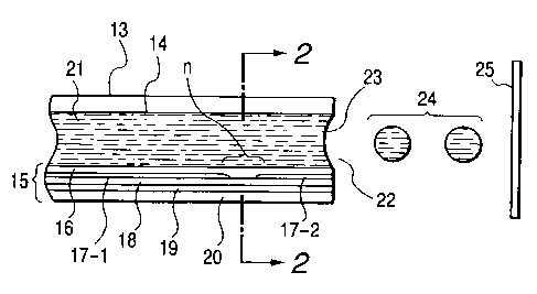
Figs. 1 and 2 are schematic sectional views
illustrating an example of the construction of a head,
which is a main component of such an image recording
apparatus. Specifically, Fig. 1 is a schematic cross-
sectional view of a head l3.taken along the flow path
of ink, and Fig. 2 is a cross-sectional view taken
along line 2-2 in Fig. 1. The head 13 is formed by
_ _ . _.~..__.__._~.__ ~.. ~
CA 02267393 1999-03-30
- 39 -
bonding a glass, ceramic, silicon or plastic plate or
the like having a flow path (nozzle) 14 through which
an ink is passed, to a heating substrate 15. The
heating substrate 15 is composed of a protective film
16 made of silicon oxide, silicon nitride, silicon
carbide or the like, electrodes 17-1 and 17-2 formed of
aluminum, gold, aluminum-copper alloy or the like, a
heating resistor layer ~l8 formed of a high-melting
material such as, HfB2, TaN or TaAl, a heat accumulating
layer 19 formed of silicon oxide, aluminum oxide or the
like, and a substrate 20 made of silicon, aluminum,
aluminum nitride or the like having a good heat
radiating property.
Now, upon application of pulsed electric signals
to the electrodes 17-1 and 17-2 of the head 13, the
heating substrate 15 rapidly generates heat at the
region shown by "n" to form bubbles in an ink 21 which
is in contact with this region. A meniscus 23 of the
ink is projected by the pressure thus produced, and the
i.nk 21 is ejected from an ejection orifice 22 through
the nozzle 14 of the head 13 toward a recording medium
25. Fig. 3 illustrates an appearance of a multi-head
composed of an array of a number of heads as shown in
Fig. 1. The multi-head is formed by closely bonding a
glass plate 27 having a number of grooves 26 t.o a
heating head 28 similar to that described in Fig: 1.
Fig. 4 illustrates an example of an ink-jet
_._ .-. _~ ____.._ . ~ _
CA 02267393 1999-03-30
- 40 -
recording apparatus in which such a head as described
above has been incorporated. In Fig. 4, reference
numeral 61 designates a blade serving as a wiping
member, one end of which is a stationary end held by a
blade-holding member to form a cantilever. The blade
61 is provided at a position adjacent to a region in
which a recording head 65 operates, and in this
embodiment, is held in 'such a form that it protrudes
into the course through which the recording head 65 is
moved. Reference numeral 62 indicates a cap for the
face of ejection openings of the recording head 65,
which is provided at a home position adjacent to the
blade 61, and is so constructed that it moves in a
direction perpendicular to a direction in which the
recording head 65 is moved, and comes into contact with
the face of the ejection openings to cap it. Reference
numeral 63 denotes an ink absorbing member provided
adjoiningly to the blade 61 and, similar to the blade
61, held in such a form that it protrudes into the
course through which the recording head 65 is moved.
The above-described blade 61, cap 62 and ink absorbing
member 63 constitute an ejection-recovery portion 64,
where the blade 61 and ink absorbing member 63 remove
water, dust and/or the like from the face of the ink-
ejecting openings. Reference numeral 65 designates the
recording head having an ejection-energy-generating
means and serving to eject the ink onto a recording
..._.__._~_ - __ .._..__ _.. ___._.. __-_.
CA 02267393 1999-03-30
- 41 -
medium set in an opposing relation to the ejection
opening face provided with the ejection openings to
conduct recording. Reference numeral 66 indicates a
carriage on which the recording head 65 is mounted so
that the recording head 65 can be moved. The carriage
66 is slidably interlocked with a guide rod 67 and is
connected (not illustrated) at its part to a belt 69
driven by a motor 68. Thus, the carriage 66 can be
moved along the guide rod 67 and hence, the recording
head 65 can be moved from a recording region to a
region adjacent thereto. Reference numerals 51 and 52
denote a feeding part from which the recording medium
is inserted, and feed rollers driven by a motor (not
illustrated), respectively. With such a construction,
the recording medium is fed to the position opposite to
the ejection opening face of the recording head 65, and
discharged from a discharge section provided with
discharge rollers 53 with the progress of recording.
In the above construction, the cap 62 in the head
recovery portion 64 is receded from the path of motion
of the recording head 65 when the recording head 65 is
returned to its home position, for example, after
completion of recording, and the blade 61 remains
protruded into the path of motion. As a result, the
ejection opening face of the recording head 65 is
wiped. When the cap 62 comes into contact with the
ejection opening face of the recording head 65 to cap
_.. _ ___~.._.._.e .~_
CA 02267393 1999-03-30
- 42 -
it, the cap 62 is moved so as to protrude into the path
of motion of the recording head 65.
When the recording head 65 is moved from its home
position to the position at which recording is started,
the cap 62 and the blade 61 are at the same positions
as the positions for the wiping as described above. As
a result, the ejection opening face of the recording
head 65 is also wiped at the time of this movement.
The above movement of the recording head 65 to
i.ts home position is made not only when the recording
is completed or the recording head 65 is recovered for
ejection, but also when the recording head 65 is moved
between recording regions for the purpose of recording,
during which it is moved to the home position adjacent
to each recording region at given intervals, where the
ejection opening face is wiped in accordance with this
movement.
Fig. 5 illustrates an exemplary ink cartridge 45
in which an ink to be fed to a head through an ink-
feeding member, for example, a tube is contained.
Here, reference numeral 40 designates an ink container
portion containing the ink to be fed, as exemplified by
a bag for the ink. One end thereof is provided with a
stopper 42 made of rubber. A needle (not illustrated)
may be inserted into this stopper 42 so that the ink in
the bag 40 for the ink can be fed to the head.
Reference numeral 44 indicates an absorbing member for
_~.a_. .._._.____._ .._. . T _
CA 02267393 1999-03-30
- 43 -
receiving a waste ink. It is preferred that the ink
container portion 40 be formed of a polyolefin, in
particular, polyethylene, at its surface with which the
ink comes into contact.
[Recording unit]
The ink-jet recording apparatus used in the
present invention are not limited to the apparatus as
described above in which the head and the ink cartridge
are separately provided. Therefore, a device in which
these members are integrally formed as shown in Fig. 6
can also be preferably used. In Fig. 6, reference
numeral 70 designates a recording unit, in the interior
of which an ink container portion containing an ink,
for example, an ink absorbing member, is contained.
The recording unit 70 is so constructed that the ink in
such an ink absorbing member is ejected in the form of
ink droplets through a head 71 having a plurality of
arifices. In the present invention, polyurethane is
preferably used as a material for the ink absorbing
member. The ink container portion may be constructed
without using the ink absorbing member by a bag for the
ink in the interior of which a spring or the like is
provided. Reference numeral 72 indicates an air
passage for communicating the interior of the recording
unit 70 with the atmosphere.
This recording unit 70 is used in place of the
recording head 65 shown in Fig. 4, and is detachably
____.__~ . _ .__.__.___.__...-_
CA 02267393 1999-03-30
- 44 -
installed on the carriage 66.
[Ink-jet recording apparatus and recording process
using piezoelectric element]
As a preferable example of an ink-jet recording
apparatus making good use of mechanical energy, may be
mentioned an On-Demand type ink-jet recording apparatus
comprising a nozzle-forming substrate having a
plurality of nozzles, pressure-generating devices
composed of a piezoelectric material and an electric
conductive material provided in an opposing relation to
the nozzles, and an ink filled around the pressure-
generating devices, wherein the pressure-generating
devices are changed by voltage applied to eject
droplets of the ink from the nozzles.
An example of the construction of a recording
head, which is a main component of such a recording
apparatus, is illustrated in Fig. 7.
The head is composed of an ink flow path 80
communicating with an ink chamber (not illustrated), an
orifice plate 81 through which ink droplets having a
desired volume are ejected, a vibration plate 82 for
directly applying a pressure to the ink, a
piezoelectric element 83. bonded to the vibration plate
82 undergoing a change according to an electric signal,
and a substrate 84 adapted to support and fix the
orifice plate 81, the vibration plate 82 and the like
thereon.
~~.~.._..~...~ _ W...~ __... _ ..._ _. r
CA 02267393 1999-03-30
- 45 -
In Fig. 7, the ink flow path 80 is formed with a
photosensitive resin or the like. The orifice plate 81
is made of a metal such as stainless steel or nickel,
and an ejection opening 85 of which is formed by
electroforming, punching by press working, or the like.
The vibration plate 82 is formed with a film of a metal
such as stainless steel, nickel or titanium and a high-
modulus resin film or the like. The piezoelectric
element 83 is made of a dielectric material such as
barium titanate or PZT.
The recording head with the above construction is
operated in such a manner that pulsed voltage is
applied to the piezoelectric element 83 to generate a
stress to cause strain, the vibration plate 82 bonded
to the piezoelectric element 83 is deformed by the
energy of the stress, and the ink in the ink flow path
80 is thus perpendicularly pressurized to eject ink
droplets (not illustrated) from the ejection opening 85
of the orifice plate 81, thereby conducting recording.
Such a recording head is used by incorporating it
into an ink-jet recording apparatus similar to that
illustrated in Fig. 4. Operation of details of the
ink-jet recording apparatus may be conducted in the
same manner as described above.
[Ink set]
The above-described inks according to the various
embodiments of the present invention constitute black
_......____ .. __ ._____. __~... _ ~
CA 02267393 1999-03-30
- 46 -
inks and can each be provided as an ink set suitable
for use in the formation of color images by combining
it with at least one color ink selected from the group
consisting of color inks comprising coloring materials
for yellow, magenta, cyan, red, blue and green,
respectively, In particular, the black inks according
to the second embodiment can extremely effectively
reduce the occurrence of bleeding when used together
with an ink comprising at least one of a water-soluble
dye having an anionic group and a compound containing
at least an anionic group, since an ionic reaction
takes place in a boundary region between both inks on a
recording medium. Examples of the water-soluble dye
having an anionic group include the conventionally
known direct dyes and acid dyes. Examples of the
compound containing at least an anionic group include
the conventionally known anionic surfactants and
anionic group-containing high-molecular compounds. In
these, pigment dispersants and the like are also
included.
(Color ink)
As coloring materials for the color inks usable
for the above ink set, may be cased publicly knoww dyes
and pigments. As the dyes, for example, acid dyes and
direct dyes may be used. As, for example, anionic
dyes, most of both dyes already known and newly
synthesized may be used so far as they have proper
_.... __. ._. ._...v.~.....~_. T . _.
CA 02267393 1999-03-30
- 47 -
color tone and density. Some of them may also by used
i.n combination. As Specific examples of the anionic
dyes, may be mentioned the following dyes:
(Coloring material for yellow)
C.I. Direct Yellow 8, 11, 12, 27, 28, 33, 39, 44, 50,
58, 85, 86, 87, 88, 89, 98, 100 and 110;
C.I. Acid Yellow 1, 3, 7, 11, 17, 23, 25, 29, 36, 38,
40, 42, 44, 76, 98 and 99;
C.I. Reactive Yellow 2, 3, 17, 25, 37 and 42; and
C.I. Food Yellow 3.
(Coloring material for red)
C.I. Direct Red 2, 4, 9, 11, 20, 23, 24, 31, 39, 46,
62, 75, 79, 80, 83, 89, 95, 197, 201, 218, 220, 224,
225, 226, 227, 228 and 229;
C.I. Acid Red 6, 8, 9, 13, 14, 18, 26, 27, 32, 35, 42,
51, 52, 80, 83, 87, 89, 92, 106, 114, 115, 133, 134,
145, 158, 198, 249, 265 and 289;
C.I. Reactive Red 7, 12, 13, 15, 17, 20, 23, 24, 31,
42, 45, 46 and 59; and
C.I. Food Red 87, 92 and 94.
(Coloring material for blue)
C.I. Direct Blue 1, 15, 22, 25, 41, 76, 77, 80, 86, 90,
98, 106, 108, 120, 158, 163, 168, 199 and 226;
C.I. Acid Blue 1, 7, 9, 15, 22, 23, 25, 29, 40, 43, 59,
62, 74, 78, 80; 90, 100, 102, 104, 117, 127., 138, 158
and 161; and
C.I. Reactive Hlue 4, 5, 7, 13, 14, 15, 18, 19, 21, 26,
_.._. _...___ _...._~__._
CA 02267393 1999-03-30
- 48 -
27, 29, 32, 38, 40, 44 and 100.
(Coloring material for black)
C.I. Acid Black 2, 4, 8, 51, 52, 110, 115, 156; and
C.I. Food Black 1 and 2.
(Solvent)
Examples of solvents or dispersion media for inks
respectively comprising such coloring materials for
color inks as described~above include water and mixed
solvents of water and a water-soluble organic solvent.
Examples of the water-soluble organic solvent include
the same solvents as those described in the first
embodiment. When such color inks are applied to a
recording medium by an ink-jet system (for example,
bubble-jet system), it is preferred that the inks be
controlled so as to have the desired viscosity and
surface tension in order for the inks to exhibit
excellent ink-jet ejection properties as described
above.
(Content of coloring material)
The content of the coloring material in each of
the color inks may be suitably selected in such a
manner that such an ink has excellent ink-jet ejection
properties and the desired color tone and density when
i.t is used in, for example, ink-jet recording. For
example, as a standard, it is preferably within a range
of from 3 to 50 $ by weight based on the total weight
of the ink. The amount of water contained in the ink
CA 02267393 1999-03-30
- 49 -
is preferably within a range of from 50 to 95 ~ by
weight based on the total weight of the ink.
[Recording apparatus and recording process using ink
sets]
When each of the above-described ink sets is used
to record color images, for example, a recording
apparatus in which 4 recording heads, each of which has
been illustrated in Fig. 3, are arranged on a carriage,
may be used. An embodiment thereof is illustrated in
Fig. 9. Reference numerals 91, 92, 93 and 94 indicate
recording units for ejecting yellow, magenta, cyan and
black inks, respectively. The recording units are
arranged on a carriage of the above-described recording
apparatus and serve to eject the respective inks in
response to recording signals. Fig. 9 shows the case
where the four recording heads have been used.
However, the present invention is not limited thereto.
For example, an embodiment, wherein ink cartridges 86
to 89 respectively containing the above four colors ink
are set in a recording head 90 in which ink flow paths
are separately formed in such a manner that the color
inks fed from the ink cartridges 86 to 89 can be
separately ejected by one recording head as shown in
Fig. 8, thereby conducting recording, is also included.
The present invention will hereinafter be
described more specifically by the following Examples
and Comparative Examples. However, the present
CA 02267393 2002-O1-31
- 50 -
invention is not limited to the following examples so
far as it does not exceed the subject matter thereof:
Incidentally, all designations of "part" or "parts" and
"%" as will be used in the following examples mean part
or parts by weight and % by weight unless expressly
noted. In the following examples, the average particle
diameter is a value measured by means of a dynamic
light scattering particle diameter measurement
*
equipment (ELS-800, trade name, manufactured by
Ohtsuka Denshi K.K.).
Examples 1 to 6:
Dispersions C-1 and C-2 were provided as carbon
black dispersions.
(Preparation of Dispersion C-1)
Dispersion C-1 was prepared in the following
manner.
A styrene-methacrylic acid-ethyl acrylate
copolymer (acid value: 350; weight average molecular
weight: 3,000; as a 20 % aqueous solution; neutralizing
agent: potassium hydroxide)~was used as a dispersant.
. The following materials were charged in a batch-wise
sand mill (manufactured by Aimex Company), and glass
beads having a diameter of 1 mm were charged as a
grinding.medium to conduct a dispersion treatment for 3
hours while cooling. with water,. . . .. .. . ..
Aqueous~solution of dispersant 30 parts
(20 % aqueous solution)
* txade mark
CA 02267393 2002-O1-31
- 51 -
Carbon black (Mogul, trade name; 20 parts
product of Cablack Co.)
Glycerol l0 parts
Water 30 parts.
The carbon black dispersion thus obtained had an
average particle diameter of 0.1 ~.m and a pH of 1OØ
(Preparation of Dispersion C-2)
Dispersion C-2 was obtained in the same manner as
the preparation of Dispersion C-1 except that self-
dispersing carbon black CAB-O-JET 200 (trade name,
product of CABOT Co.; solid content: 20 ~; having a
sulfonic group as a functional group on its surface)
was used. The carbon black dispersion thus obtained
had an average particle diameter of 0.13 ~,m and a pH of
7Ø Preparation of Dispersions MC-1 and MC~-2 of
resins encapsulating a coloring material:
Dispersions MC-1 and MC-2 were also provided as
dispersions of resins encapsulating a coloring
material.
(Preparation of Dispersion MC-1)
The following.materials were mixed into a
solution.
C.I. Solvent Black 3 . 10 parts
Styrene-acrylic acid copolymer (acid
value: 200; molecular weight: 30,000)
40 parts
* trade-mark
CA 02267393 1999-03-30
- 52 -
Methyl ethyl ketone 50 parts.
The resultant solution was phase inversion-
emulsified in water using sodium hydroxide as a
neutralizing agent, and methyl ethyl ketone was removed
to finally obtain an aqueous dispersion of
microcapsules having an average particle diameter of
0.08 ~u,m containing solids at a concentration of 20 $.
(Preparation of Dispersion MC-2)
An aqueous dispersion of microcapsules having an
average particle diameter of 0.13 ~m containing solids
at a concentration of 20 $ was finally obtained in the
same manner as the preparation of Dispersion MC-1
except that the resin used in Dispersion MC-1 was
changed to a styrene-acrylic acid-methyl methacrylate
terpolymer (acid value: 250; molecular weight: 25,000).
After the respective dispersions provided in the
above-described manner were mixed so as to give solid
contents in their corresponding proportions shown in
Table 1, glycerol and isopropyl alcohol were mixed with
each of the mixtures in such a manner that the
concentrations of glycerol and isopropyl alcohol amount
to 16 $ and 4.0 $, respectively, thereby preparing
respective inks finally containing carbon black and the
resin encapsulating the coloring material at a
concentration of 8 $ in terms.of total solid content in
each ink.
"C.B./MC" shown in Table 1 indicates final
....__...._... _._._. _.._ _. . ~
CA 02267393 1999-03-30
- 53 -
concentrations of the respective solids (i.e. carbon
black and the resin) in each ink prepared. More
specifically, it indicates that, for example, Ink A
according to Example 1 was prepared in such a manner
that the solid contents of carbon black and the resin
encapsulating the coloring material amount to 1.5 $ and
6.5 ~, respectively. Incidentally, the amount of
carbon black in Example's 1 to 3 in Table 1 means the
total solid content of carbon black and the dispersant.
On the other hand, the amount of carbon black in
Examples 4 to 6 means an amount of carbon black alone
because no dispersant was used for the carbon black.
The six inks A, B, C, D, E and F thus prepared
were separately charged into an ink tank for black of a
BJ Cartridge BC-21 installed in a color BJ printer BJC-
420J (trade name; manufactured by Canon Inc.), and the
cartridge was set in BJC-420 to conduct printing on
recording paper Canon PB Paper (trade name, product of
Canon Inc.; paper for common use in BJ-
electrophotography) in accordance with the 360 x 360
DPI, HQ mode for plain paper of BJC-420J.
Comparative Examples 1 to 3:
Inks G and H containing only their corresponding
carbon black shown in Table 1, and Ink I containing
only its corresponding resin encapsulating a coloring
material shown in Table 1 were used to conduct printing
in exactly the same manner as in Examples 1 to 6.
CA 02267393 1999-03-30
- 54 -
Table 1
Resin encapsulating
Ink C.B. dis ersion colorin material C.B. MC
Ex. 1 A C-1 MC-1 1.5/6.5
Ex. 2 B C-1 MC-1 3.0/5.0
Ex. 3 C C-1 MC-1 4.0/4.0
Ex. 4 D C-2 MC-2 1.5/6.5
Ex. 5 E C-2 MC-2 3.0/5.0
Ex. 6 F C-2 MC-2 4.0/4.0
Comp. G C-1 Not used 8.0/0
i Ex
. 1
i
Comp. H C-2 Not used 8.0/0
Ex. 2
Comp. I Not used MC-1 0/8.0
Ex. 3
The thus-obtained prints were evaluated in the
following manner:
Optical density of image:
After a solid printed sample was left to stand
for 12 hours after its printing, its optical density
was measured by means of a reflection densitometer,
Macbeth RD-918 (trade name, manufactured by Macbeth
Company). The evaluation result was ranked in
accordance with the following standard:
A: Optical density was not lower than 1.35,-
B: Optical density was from 1.2 to 1.34; and
C: Optical density was lower than 1.2.
CA 02267393 1999-03-30
- 55 -
Water fastness:
The same solid printed sample as that used in the
evaluation of the optical density of image was used and
left to stand for 12 hours after the printing. The
image sample was then dipped in tap water for 3 seconds
and dried to measure its optical density by means of
the reflection densitometer described above, whereby
the percent retention of the optical density was found
from the optical densities before and after the water
fastness test to use it as a measure of the water
fastness. The evaluation result was ranked in
accordance with the following standard:
A: Percent retention of optical density was not
lower than 90 %;
B: Percent retention of optical density was not
lower than 70 % but lower than 90 %;
C: Percent retention of optical density was lower
than 70%.
Resistance to line marker:
Upon elapsed time of 1 hour after the printing of
characters, the character portion of the resulting
print sample was marked once under ordinary writing
pz:essure with a yellow fluorescent pen, Spot Lighter
Yellow, (trade name; product of Pilot Pen Co., Ltd.),
whereby the resistance to line marker was. ranked in
accordance with the following evaluation standard:
A: Neither bleeding nor stain on white portions
._____._..w.~v_ . . _ . _ ~. _. ._._..... .... . . ._ ~
CA 02267393 1999-03-30
- 56 -
was observed in the print sample, and a pen
point was also not stained;
B: No stain on white portions was observed in the
print sample, but a pen point was somewhat
stained; and
C: Stain on white portion was observed in the
print sample.
Rub-off resistance:
Upon elapsed time of 4 hours after the printing
of an image, silbon paper was placed on the paper
printed, and an 1-kg weight having a bottom area of 5
cm square was then placed on the silbon paper. The
silbon paper was then pull out to visually observe
whether the unprinted portions (white portions) of the
printed paper and the silbon paper were stained by the
rubbing between the printed portions of the printed
paper and the silbon paper. The rub-off resistance was
ranked in accordance with the following evaluation
standard:
A: No stain was observed in both white portions
and silbon paper;
B: Stain was observed in the silbon paper alone;
and
C: Stain was observed in both white portions and
silbon paper.
Ejection stability:
An 1-dot vertical line was printed on recording
_..__.r_.~__. . ____.~.._. _... ._ _ .. _~.~ ......_ T
CA 02267393 1999-03-30
- 57 -
paper at the beginning of use of Cartridge BC-21. Text
printing was conducted until the Cartridge BC-21 was
consumed. The cartridge right before it was consumed
was used to print an 1-dot vertical line on another
recording paper. These recording paper samples were
visually observed from a position 25 cm distant,
thereby comparing the result of the printing by the
cartridge at the beginning of use with the result of
the printing by the cartridge right before it was
consumed to rank the ejection stability in accordance
with the following evaluation standard:
A: No difference was observed between both
samples;
B: Deviation of dot impact was observed in a part
of the vertical line printed by the cartridge
right before it was consumed, but the line
could be recognized as a straight line; and
C: Deviation of dot impact was clearly observed
in the vertical line printed by the cartridge
right before it was consumed, and the vertical
line could be recognized to deviate.
The evaluation results are shown in Table 2.
. ..._ . _ ~ . ..._. . _ ___.__.r _
CA 02267393 1999-03-30
- 58 -
Table 2
Optical Water Resistance Rub-off Ejection
density fast- to line resistance stabil-
ness marker ity
Ex. B A A A B
1
Ex. B A A A B
2
Ex. A A B A B
3
Ex. A A A A A
4
Ex. A A A A A
Ex. A A A A A
6
Comp. A A C C B
Ex.
1
Comp. A A C C A
Ex.
2
Comp. C A A A A
Ex.
3
It is understood from Table 2 that the inks
according to the present invention are inks for ink-
jet, which can provide an image sufficiently high in
optical density on plain paper and excellent in water
fastness, resistance to line marker and rub-off
resistance and are sufficiently good in ejection
stability. The inks of the sole system of carbon black
and the ink of the sole system of the resin
encapsulating the coloring material could not obtain
.~_.~__._____.. . _..... __.__
CA 02267393 1999-03-30
- 59 -
results satisfying all the optical density of image,
water fastness, resistance to line marker, rub-off
resistance and ejection stability at the same time.
Examples 7 to 12:
Dispersions C-3 and C-4 were provided as carbon
black dispersions.
(Preparation of Dispersion C-3)
Dispersion C-3 was prepared in the following
manner.
Cationic Polymer P-1 (weight average molecular
weight: 11,000, pH of aqueous solution: 3.26)
containing acrylamide and
trimethylaminopropylacrylamide sulfate as monomers in a
weight ratio of 70:30 was used as a dispersant to
prepare the following Carbon Black Dispersion C-3.
Aqueous solution of Cationic Polymer 20 parts
P-1 (solid content: 20
Carbon black #2600 (product of 10 parts
Mitsubishi Kagaku Co., Ltd.)
Diethylene glycol 5 parts
Isopropyl alcohol 5 parts
Water 60 parts.
The above materials were charged in a batch-wise
vertical sand mill (manufactured by Aimex Company), and
-25 glass beads having a diameter of 1 mm were charged as a
grinding medium to conduct a dispersion treatment for 3
hours while cooling with water. After the dispersion
_..~~...._ . . ._......_. __.~.~.-~,~~.._.__. _. __._._... ~ _
CA 02267393 1999-03-30
- 60 -
treatment, the dispersion had a viscosity of 28 cP and
a pH of 4.05. This dispersion was centrifuged to
remove coarse particles, thereby obtaining Dispersion
C-3 having an average particle diameter of 0.12 ~tm.
The dispersion had a solid content of 10 $ in total.
(Preparation of Dispersion C-4)
Dispersion C-4 was prepared in the following
manner.
After 10 g of carbon black having a surface area
of 230 mz/g and a DBP oil absorption of 70 m1/100 g, and
3.06 g of 3-amino-N-ethylpyridinium bromide were
thoroughly mixed with 72 g of water, 1.62 g of nitric
acid were added dropwise to the mixture, followed by
stirring at 70°C. After several minutes, a solution
with 1.07 g of sodium nitrite dissolved in 5 g of water
was further added to the mixture, and the resultant
mixture was stirred for an additional 1 hour. The
resultant slurry was filtered through filter paper
(Toyo Filter Paper No. 2, trade name; product of
Advantes Co.), and the resultant pigment particles were
fully washed with water and dried in an oven controlled
to 110°C. Water was added to the dry pigment to prepare
an aqueous dispersion of the pigment having a pigment
concentration of 10 %. The above-described process was
followed to introduce a group of the chemical formula
N~ C~
_ _ ~..~_~_.... ~ .
CA 02267393 1999-03-30
- 61 -
in the surface of the carbon black.
Preparation of Dispersions MC-3 and MC-4 of resins
encapsulating a coloring material:
Dispersions MC-3 and MC-4 were also provided as
dispersions of resins encapsulating a coloring
material.
(Preparation of Dispersion MC-3)
The following materials were mixed into a
solution.
C.I. Solvent Black 3 10 parts
Styrene-N,N-dimethylaminoethyl
methacrylate copolymer (molecular
weight: 40,000) 40 parts
Methyl ethyl ketone 50 parts.
The resultant solution was phase inversion-
emulsified using acetic acid as a neutralizing agent,
and methyl ethyl ketone was removed to finally obtain
an aqueous dispersion of microcapsules having an
average particle diameter of 0.08 ~m containing solids
at a concentration of 20 $.
(Preparation of Dispersion MC-4)
An aqueous dispersion of microcapsules having an
average particle diameter of 0.13 ~,m containing solids
at a concentration of 20 $ was finally obtained in the
same manner as the preparation of Dispersion MC-3
except that the resin used in Dispersion MC-3 was
changed to a styrene-N,N-dimethylaminopropyl
-.~.~..~. T
CA 02267393 2002-O1-31
, ' - 62 -
methacrylate copolymer (molecular weight: 35,000).
After the respective dispersions provided in the
above-described manner were mixed so as to give solid
contents in their corresponding proportions :shown in
Table 3, glycerol and isopropyl alcohol were mixed with
each of the mixtures in such a manner that the
concentrations of glycerol and isopropyl alcohol amount
to 16 °s and 4.0 ~, respectively, thereby preparing
respective inks finally containing carbon black and the
resin encapsulating the coloring material at a
concentration of 8 ~ in terms of total solid content in
each ink. C.B./MC shown in Table 3 indicates final
concentrations of the respective solids in each ink
prepared. More specifically, it indicates that Ink A
according to Example 7 was prepared in such a manner
that the solid contents of carbon black and t:he resin
encapsulating the coloring material amount to 1.5 o and
6.5 0, respectively. The same shall apply hereinafter.
Incidentally; the amount of carbon black in Examples 7
to 9 in Table 3 means the total solid content: of carbon
black and the dispersant. On the other hand, the
amount of carbon black in Examples 10 to 12 means an
amount of carbon black alone because no dispersant was
used for the carbon black.
The six Inks ~ J, K, K, M, Iii and 0 . thus prepared
were separately charged-into an ink tank for black of a
BJ Cartridge BC-21 installed in a color BJ painter
* trade-mark.
CA 02267393 2002-O1-31
. - 63 -
(BJC-420J, trade name; manufactured by Canon Inc.), and
the cartridge was set in BJC-420*to conduct Lorinting on
recording paper, Canon PB Paper, (trade name, product
of Canon Inc.; paper for common use in BJ-
electrophotography) in accordance with the 360 x 360
DPI, HQ mode for plain paper of BJC-420J. The thus-
obtained prints were evaluated as to optical density of
image, water fastness, resistance to line marker, rub-
off resistance and ejection stability in exactly the
same manner as in Examples 1 to 6. The evaluation
results are shown in Table 4.
Comparative Examples 4 to 6:
Inks P and Q containing only their corresponding
carbon black shown in Table 3, and Ink R containing
only its corresponding resin encapsulating a coloring
material shown in Table 3 were prepared in the same
manner as in the inks according to Examples ~' to 12 and
evaluated as to optical density of image, wager
fastness, resistance to line marker, rub-off resistance
and ejection stability in exactly the same manner as in
Examples 7.to 12. The evaluation results are shown in
Table 4.
* trade-mark
CA 02267393 1999-03-30
- 64 -
Table 3
Resin encapsulating
Ink C.B. dis ersion colorin material C.B. MC
Ex. J C-3 ~ MC-3 1.5/6.5
7
Ex. K C-3 i MC-3 3.0/5.0
8
Ex. L C-3 MC-3 4.0/4.0
9
Ex. M C-4 !, MC-4 1.5/6.5
I i
Ex. N C-4 ~ ''I MC-4 3.0/5.0
11 i
Ex. O C-4 ~, MC-4 4.0/4.0
12 I
Comp. P C-3 ! Not used 8.0/0
Ex.
4
Comp. Q C-4 ~~, Not used 8.0/0
Ex.
5
Comp. R Not used MC-3 0/8.0
Ex.
6
Optical density, water-fastness, resistance to line
marker, rub-off resistance and efection stability were
evaluated in the same manner as in Examples 1 to 6.
The results are shown in Table 4.
., .....__ _ _.~...._ ._.. ..~..-.~.~r ~-. ~.___.___ _ T
CA 02267393 1999-03-30
- 65 -
Table 4
Optical Water Resistance Rub-off Ejection
density fast- to line resistance stabil-
ness marker ity
Ex. 7 B A A A B
Ex. 8 B A A A B
Ex. 9 A A B A B
Ex. 10 A A A A A
Ex. 11 A A A A A
Ex. 12 A A A A A
Comp. A A C C B
Ex. 4
Comp. A A C C A
Ex. 5
Comp. C A A A A
Ex. 6
It is understood from Table 4 that the use of the
inks according to the above examples can provide images
sufficiently high in optical density on plain paper and
excellent in water fastness, resistance to line marker
and rub-off resistance. As shown in Table 4, the inks
of the sole system of carbon black and the ink of the
sole system of the resin encapsulating the coloring
material could not obtain results satisfying all the
optical density of image, water fastness, resistance to
___~_~_ . _. _.y..._~_ .___ -~ _....__~...._~.~ ._. T
CA 02267393 2002-O1-31
- 66 -
line marker, rub-off resistance and ejection stability
at the same time.
Examples 13 to 18:
Inks J to O prepared in Examples 7 to 12,
respectively, were separately charged into an ink tank
*
for black of a color BJ printer, BJC-610JW, (trade
name; manufactured by Canon Inc.) to use them for
evaluation in Examples l3 to 18. Color inks
exclusively prepared for BJC-610JW were used as color
inks. Black characters were printed in a color solid-
printed background on PB paper (product of Canon Inc.),
thereby~evaluating Inks J to 0 as to resistance to
color bleed between a black image formed with each of
such inks and a color image. More specifically,
resistance to color bleed between black and ~~ellow,
resistance to color bleed between black and cyan, and
resistance to color bleed between black and magenta
were separately evaluated.
As a control example, a black ink and color inks
exclusively prepared for BJC-610JL~T were used to
evaluate them as to resistance to color bleed in the
same manner as described above. As a result, in each
' of wExariiples 13 to 18, color bleeds were reduced
compared with the control example, no exudation of the
25w black characters into the color background occurred,
and the sharpness of the black characters was; also
recognized to be improved compared with the control
* trade-mark
CA 02267393 2002-O1-31
' - 67 -
example.
At this time, the optical density, water
fastness, resistance to line marker and rub--off
resistance of the images formed with the black inks
according to Examples 13 to 18 were evaluated (printing
was conducted in accordance with Bk accent mode). As a
result, the same results as in Examples 7 tc~ 12 were
obtained.
Examples 19 to 24:
Dispersions MC=5 was provided as a dispersion of
a resin encapsulating carbon black as a coloring
material.
(Preparation of Dispersion MC-5)
The following materials were mixed and dispersed.
Carbon black MCF-88 (trade name; 20 parts
product of Mitsubishi Kagaku Co., Ltd.)
Styrene-N,N-dimethylaminoethyl 40 parts
methacrylate copolymer (molecular
weight: 45,000)
Methyl ethyl ketone 40 parts.
The resultant mixture was phase inversion-
emulsified using acetic acid as a neutralizing agent,
and methyl ethyl ketone~was~removed to~final.ly obtain
an aqueous dispersion of a cationic resin encapsulating
2-5 ~ carbon b7.ack . having an average particle. diameter of..
0.10 ~m containing solids at a concentration of 20 0.
After the aqueous dispersion MC-5 of the carbon
* trade=mark
CA 02267393 1999-03-30
- 68 -
black-containing resin provided in the above-described
manner and the carbon black dispersion C-3 and C-4
prepared in Examples 7 to 12 were mixed so as to give
solid contents in their corresponding proportions shown
in Table 5, glycerol, propylene glycol and isopropyl
alcohol were mixed with each of the mixtures in such a
manner that the concentrations of glycerol, propylene
glycol and isopropyl alcohol amount to 7.0 ~, 8.0 $ and
4.0 $, respectively, thereby preparing respective inks
finally containing carbon black and the resin
encapsulating the carbon black at a concentration of 8
$ in terms of total solid content in each ink.
Table 5
Resin encapsulating
Ink C.B. dis ersion colorin material C.B. MC
Ex. S C-3 MC-5 1.5/6.5
19
Ex. T C-3 MC-5 3.0/5.0
Ex. U C-3 MC-5 4.0/4.0
21
20 Ex. V C-4 MC-5 1.5/6.5
22 i
Ex. W C-4 MC-5 3.0/5.0
23
Ex. X C-4 MC-5 4.0/4.0
24
The inks thus obtained were evaluated as to
optical density of image, water fastness, resistance to
line marker, rub-off resistance and ejection stability
. ____..._ _ _~~ ~.__ _ .. r _ _
CA 02267393 1999-03-30
- 69 -
in the same manner as in Examples 7 to 12. However,
the ranking of the optical density of image was
conducted in accordance with the following standard:
AA: Optical density was not lower than 1.4;
A: Optical density was from 1.35 to 1.39;
B: Optical density was from 1.2 to 1.34; and
C: Optical density was lower than 1.2.
The evaluation results are shown in Table 6.
Table 6
Optical Water Resistance Rub-off Ejection
density fast- to line resistance stabil-
ness marker ity
Ex. B A A A B
19
Ex. A A A A A
Ex. A A A A A
21
Ex.. AA A A A A
22
Ex. AA A A A A
23
Ex. AA A A A A
24
Examples 25 to 30:
Color inks having their corresponding
compositions shown below were prepared.
Yellow ink:
C.I. Direct Yellova 86 3:5 parts
Glycerol 10.0 parts
~._~w_ . _..._.._. T
CA 02267393 2002-O1-31
70 -
Acetylenol EH (trade name, product of
Kawaken Fine Chemicals Co., Ltd.;
acetylene glycol type surfactant) 1:0 parts
Water 85:5 parts.
Magenta ink:
C.I. Acid Red 285 3.5 parts
Glycerol 10.0 parts
Acetylenol EH (ditto) 1.0 part
Water 85.5 parts.
Cyan ink:
C.I. Acid Blue 199 3.5 parts
Glycerol 10.0 parts
Acetylenol EH (ditto) 1.0 part
Water 85.5 parts.
These inks were respectively charged into ink
tanks for color ink of a color BJ printer BJ(:-610JW
(trade name; manufactured by Canon Inc.). The black
inks S to X prepared in Examples 19 to 24,
respectively; were separately charged into an ink tank
for black ink of the color BJ printer, BJC-610JW; to
use them for evaluation in Examples 25 to 30.
Resistance to color bleed between each of the black
inks S to X and the above-described color inks of
yellow, magenta and cyan was evaluated in exactly the
. ~ same ma~nner~-as~ in Example 13 to.. 18. The results. ,
thereof were the same as in~Examples 13 to 18. No
exudation'into the color background occurred in the
* trade-mark
CA 02267393 1999-03-30
- 71 -
black images formed with the black inks S to X, and the
sharpness of the black characters was also improved
compared with the control example. At this time, the
optical density, water fastness, resistance to line
marker and rub-off resistance of the images formed with
the black inks alone were evaluated (printing was
conducted in accordance with Bk accent mode). As a
result, exactly the same results as in Examples 19 to
24 were obtained.
According to the present invention, as described
above, there can be provided inks which can provide
images improved in resistance to line marker and rub-
off resistance without impairing the merits of a
pigment ink that it can provide images excellent in
optical density and water fastness, and moreover are
also excellent in reliability (ejection durability,
ejection stability, anti-clogging property, etc.) upon
ink-jet recording.
It is also possible to form images having
excellent resistance to line marker and rub-off
resistance in addition to high optical density of image
and excellent water fastness.
By the encapsulation in a resin, the hydrophobic
group of the resin is basically arranged inside a
capsule, while the hydrophilic group of the resin is
arranged outside the capsule. Therefore, the resin is
hard to adhere to the ejection opening face of a
.~..~_.__._.. . _ ....~.._ ._ _ __ _ _ T . . . __
CA 02267393 1999-03-30
- 72 -
recording head when the ejection opening face is
subjected to a water-repellent treatment, and so the
resin can be effectively prevented from depositing on
the ejection opening face of the ink-jet head.
Therefore, the ejection stability of the ink can be
still more improved.
According to the present invention, the problems
of a pigment ink can also be offset without impairing
the merits of the pigment ink. More specifically,
there can be stably provided images high in optical
density and excellent in water fastness, resistance to
line marker and rub-off resistance. When a resin
capsule is used as the resin encapsulating a coloring
material, the hydrophobic group of the resin is
basically arranged inside a capsule, while the
hydrophilic group of the resin is arranged outside the
capsule. Therefore, the resin is hard to adhere to the
ejection opening face of a recording head when the
ejection opening face is subjected to a water-repellent
treatment, and so the resin can be prevented from
depositing on the ejection opening face of the ink-jet
head. Therefore, the ejection stability of the ink can
be still more improved.
When a multi-color image is formed with at least
two inks according to the present invention by ink-jet
recording, bleeding on a recording medium can be
.. ._~_ ~...-..~.-..~ . _... ~ r .
CA 02267393 1999-03-30
- 73 -
effectively lessened in addition to the above-described
effects.
.._..._._~.. . _._. ._._w _.._w___. . T