Note: Descriptions are shown in the official language in which they were submitted.
CA 02267546 1999-03-30
TOOL CASES WITH PIVOTABLE HOLDERS
BACKGROUND OF THE INVENTION
This invention relates to tool containers or cases, particularly ones used
for sale and/or storage of items such as sockets, bits, drills and/or other
tool
components, accessories and miscellaneous items, for use with corresponding
tools
such as socket wrenches, screwdrivers, drills, small power tools, etc., which
may or
may not be sold and/or stored in the same case. Such cases include those
commonly
referred to as gift cases, tool cases or accessory cases, which may act as
point-of-
purchase holders and/or which may serve as permanent holders.
Cases of this general type are well known, and typically include an open
box portion and a lid hinged to the box portion, with a clip, a clasp or the
like to hold the
lid closed. Various means are provided within such cases for holding tools,
tool
components and/or accessories, such as those mentioned in the preceding
paragraph,
hereinafter simply referred to as "items" or "the items", for convenience.
Most cases of
this type are configured to be stacked horizontally or to be hung vertically
at the point
of sale, but to be opened when lying on a horizontal surface, although some
may be
configured to hang on the wall or to sit generally upright.
Many such cases have multiple storage recesses or compartments forthe
items. When such recesses or compartments are oriented such that the items are
oriented parallel or close to parallel to the main plane of the case, it can
be difficult to
remove the items. Angling the recesses or compartments so that the items are
oriented
at an angle to the main plane of the case makes the items more accessible, but
normally takes up much more space, and therefore normally requires a larger
case than
is desirable.
There is a need for an improved case which would provide for a typical
point of sale display, which would be capable of hanging vertically or
standing vertically
or somewhat inclined, and which would provide easy access to items without
wasted
space.
-1-
CA 02267546 1999-03-30
SUMMARY OF THE INVENTION
In view of the preceding, it is an object of the invention to provide an
improved case for items such as tools, tool components and accessories, etc.
as
referred to above, configured for generally upright orientation. By "generally
upright",
what is meant is that the main plane of the case is intended to be vertical,
or somewhat
inclined or angled back from the vertical as illustrated in the following
description of the
preferred embodiment, as opposed to being horizontal or nearly horizontal. By
"main
plane", what is meant is the plane to which most elements of the case are
closest, i.e.
normally a plane parallel to and midway between the front and back of the
case.
To improve access to the items in the case, the case has at least one and
preferably several holders which are rotatably mounted therein, for rotation
between a
storage position and an access position. Each holder may have multiple
recesses to
accommodate multiple small items, or perhaps only one or two recesses for only
one
or two larger items.
In the access position, the holders are oriented at an angle to the main
plane of the case, such that the items angle outwardly from the case for
easier access.
In the storage position, each holder is more aligned with the main plane of
the case, for
example oriented parallel or close to parallel to the main plane, to minimize
space
requirements.
In preferred embodiments, to minimize space requirements, any holders
which are in the access position must be rotated to their storage positions in
order for
the lid to close. With the holders in the access position, the lid could not
be closed,
unless excessive space was wasted beneath the lid. If any holders are in the
access
position, the action of closing the lid moves them to the storage position, by
contacting
one or more of the holders, or one or more items in the holders. In
alternative
embodiments, which are less preferable, it could be possible to close the lid
without
rotating the holders to their storage positions.
Another aspect of the invention is that where two or more rotatable
holders are used in the case, they preferably are ganged together, such that
they rotate
in unison. If rotated to their storage positions by closing of the lid as in
the preferred
embodiment, the lid thus could act on any individual holder or item(s) in any
individual
holder.
-2-
CA 02267546 2007-10-25
In another aspect, there is provided a tool container, having a base and a lid
connected thereto for movement between open and closed positions, said base
having at
least one pivotable component holder pivotally mounted therein for pivoting
movement
between a storage position and an access position, each said pivotable
component
holder being biased towards said access position when said lid is open, said
tool
container having actuation means responsive to closing of said lid, said lid
not directly
connected to any said pivotable component holder, said actuation means being
configured so as to contact a first said pivotable component holder as said
lid closes so
as to gradually rotate said first pivotable component holder to its storage
position, said
actuation means comprising an element extending from said lid so as to contact
a cam to
rotate said cam, said cam being connected to a first pivotable component
holder via an
actuation bar, said element urging each said pivotable component holder to its
storage
position as said lid closes.
In another aspect, there is provided a tool container, having a base and a lid
connected thereto for movement between open and closed positions, said base
having at
least one pivotable component holder pivotally mounted therein for pivoting
movement
between a storage position and an access position, each said pivotable
component
holder being biased towards said access position when said lid is open, said
tool
container having actuation means responsive to closing of said lid, said lid
not directly
connected to any said pivotable component holder, said actuation means being
configured so as to contact a first said pivotable component holder as said
lid closes so
as to gradually rotate said first pivotable component holder to its storage
position, said
actuation means comprising an element extending from said lid so as to contact
a first
one of at least two pivotable component holders, said element being shaped so
as to
gradually rotate each said pivotable component holder to its storage position
as said lid
closes, said pivotable component holders being ganged with said first
pivotable
component holder by ganging means.
In another aspect, there is provided a tool container, having a base and a lid
connected thereto for movement between open and closed positions, said base
having at
least one pivotable component holder pivotally mounted therein for pivoting
movement
between a storage position and an access position, each said pivotable
component
holder being biased towards said access position when said lid is open, said
tool
container having actuation means responsive to closing of said lid, said lid
not directly
connected to any said pivotable component holder, said actuation means being
configured so as to contact a first said pivotable component holder as said
lid closes so
as to gradually rotate said first pivotable component holder to its storage
position, said
-2a-
CA 02267546 2007-10-25
actuation means comprising a clip removably mounted on a linkage arm between
said lid
and a body of said container, said clip having an angled surface positioned to
contact a
first pivotable component holder and being shaped so as to gradually rotate
each said
pivotable component holder to its storage position as said lid closes.
In another aspect, there is provided a tool container, having a base and a lid
connected thereto for movement between open and closed positions, said base
having at
least one pivotable component holder pivotally mounted therein for pivoting
movement
between a storage position and an access position, each said pivotable
component
holder being biased towards said access position when said lid is open, said
tool
container having actuation means responsive to closing of said lid, said lid
not directly
connected to any said pivotable component holder, said actuation means being
configured so as to contact a first said pivotable component holder as said
lid closes so
as to gradually rotate said first pivotable component holder to its storage
position, said
actuation means comprising a tab extending from a first pivotable component
holder so
as to be contacted by a portion of said lid when said lid closes, said contact
rotating each
said pivotable component holder to its storage position as said lid closes.
In another aspect, there is provided a tool container, having a base and a lid
connected thereto for movement between open and closed positions, said base
having at
least one pivotable component holder pivotally mounted therein for pivoting
movement
between a storage position and an access position, each said pivotable
component
holder being biased towards said access position when said lid is open, said
tool
container having actuation means responsive to closing of said lid, said lid
not directly
connected to any said pivotable component holder, said actuation means being
configured so as to contact a first said pivotable component holder as said
lid closes so
as to gradually rotate said first pivotable component holder to its storage
position, multiple
pivotable component holders mounted in at least one removable tray, said
actuation
means urging each said pivotable component holder to its storage position as
said lid
closes.
In another aspect, there is provided A tool container having at least one tool
holding position therein and at least one pivotable component holder pivotally
mounted
therein for pivoting movement between a storage position and an access
position, each
said pivotable component holder being biased towards said access position,
said tool
container having actuation means responsive to placement of a tool in said
tool holding
position, said actuation means urging each said pivotable component holder to
said
storage position as said tool is placed in said tool holding position.
-2b-
CA 02267546 1999-03-30
In use, the case is intended to be oriented generally upright, as defined
above. Preferably, it is self-supporting, so that it can sit generally upright
on a
workbench, for example, and/or it can have mounting holes or other means to
enable
it to be hung on a wall or toolrack.
Different embodiments provide a variety of options as to how the case can
operate. For example, in some embodiments, when the lid of the case is opened
or not
present, the pivot points for the holders may be positioned such that gravity
keeps the
holders in their storage positions until they are rotated to their access
positions. Once
the holders are in the access position, they preferably remain there by
gravity.
Alternatively, the holders may rotate to the access position automatically
upon opening of the lid, either by gravity or by virtue of a spring, and may
be returnable
to their storage positions only by closing the lid.
As another alternative, the holders may be biased to rotate to the access
position by gravity or by a spring, but may be prevented from doing so by
releasable
retention means such as catch or detent arrangement or the like. The user
would
release the retention means when wanting to have the holders move to the
access
position, and could move the holders back to the storage position and re-
engage the
retention means at any desired time.
In yet another embodiment, there may be enough friction provided that
the holders stay in whatever position they are placed.
In all embodiments, closing the lid preferably causes any holders which
are in the access position to be rotated back to the storage position.
Preferably, there are multiple holders, and preferably they are ganged
together via at least one gang bar such that the ganged holders move together.
Furtherfeatures of the invention will be described orwill become apparent
in the following detailed description.
BRIEF DESCRIPTION OF THE DRAWINGS
The invention will now be described in detail with reference to the
accompanying drawings, in which:
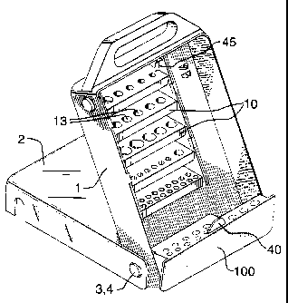
Fig. 1 is a perspective view of a preferred embodiment of the case, with
the lid open and the tool holders in their access position;
-3-
CA 02267546 1999-03-30
Fig. 2 is a perspective view with the lid closed;
Fig. 3 is a front view, with the lid closed;
Fig. 4 is an exploded perspective, showing the main components of the
case;
Figs. 5A-5E are sequential side cross-sectional views, starting with the
case closed in Fig. 5A, leading to the lid being fully open and the case being
supported
by it in Fig. 5E;
Figs. 6A and 6B are side cross-sectional views, Fig. 6A showing the tool
holders in the storage position, and Fig. 6B showing the tools holders in the
access
position;
Fig. 7 is a cross-sectional view of the catch which holds the lid closed;
Fig. 8 is a front view of just one example of an alternative holder layout;
Fig. 9 is a cross-sectional view of the Fig. 8 alternative embodiment;
Fig. 10 is a perspective view of an alternative embodiment of the base,
showing a spring used to bias the holders towards the access position;
Fig. 11 is an exploded perspective view of one of the holders, showing a
possible detent arrangement; and
Fig. 12 is a perspective view of an alternative embodiment, showing an
optional fold-down bin in the front of the lower rotatable holder.
DETAILED DESCRIPTION OF THE PREFERRED EMBODIMENTS
The case of the invention includes a main box portion or "base" 1 and a
lid 2 hinged to the base, for example by two circular openings 3 on the lid
which fit over
circular projections 4 on the base. A clip 47 or other suitable securing means
holds the
lid shut. The base typically is blow molded or injection molded. One or more
areas
may be provided with holders for various items as aforesaid, either integral
with the
base, or on panels or other holders which are attached to the base. One or
more of
those holders attached to the base may be pivotable holders 10, which are
rotatable
between a storage position and an access position as explained above.
Various items 12 as aforesaid may be stored in recesses 13 in the
pivotable holders 10. Each pivotable holder may have a number of item-holding
clips,
-4-
CA 02267546 1999-03-30
posts, recesses or other suitable means for holding the items, or may simply
be a small
bin or number of bins.
Each pivotable item holder 10 is mounted between side walls 14, via pivot
pins 16 engaging in suitable holes or recesses. The side walls 14 may be the
wall of
the base itself, or as best seen in Fig. 4, there may be a module 17 which has
two side
walls 14, the module snapping into the base between an outside wall of the
base and
an intermediate wall 15.
In the preferred embodiment, there are several pivotable holders 10, at
least some and preferably all of which are ganged together via a gang bar 18,
so that
when one is rotated, they all rotate. The gang bar connects the pivotable
holders via
gang pins 20 on the holders which fit into holes 22 in the gang bar (or bars,
since one
could be provided at either end of the holders if desired). The preferred
embodiment
also includes a particularly large pivotable holder 100 which is pivotally
mounted
between the side walls of the base, across the bottom of the base.
As explained in the above summary of the invention, different
embodiments provide a variety of options as to how the case can operate. Thus
depending on the preferred configuration for any particular case, the pivot
pins 16 may
be positioned so that the holders rotate or do not rotate by gravity from one
position to
the other, as desired. Thus in some embodiments, when the lid of the case is
opened
or not present, the pivot points for the holders may be positioned such that
gravity
keeps the holders in their storage positions until they are rotated to their
access
positions, and then once they are in the access position, the pivot points may
be such
that the holders remain there by gravity.
Alternatively, the pivot points may be selected such that the holders may
rotate or tend to rotate by gravity to the access position automatically upon
opening of
the lid. Or, as shown in Fig. 10, a leaf spring 58 or some other suitable
spring
arrangement could be used to rotate ortend to rotate the holders to the access
position.
If the holders are biased to rotate to the access position by gravity or by
a spring, in some embodiments they may be prevented from doing so by
releasable
retention means such as a catch or detent arrangement or the like. This is
particularly
desirable if it is intended that the lid of the case will be removed, as for
permanent wall
hanging via wall mounting holes 80. The releaseable retention means could be a
-5-
CA 02267546 1999-03-30
special catch 47, for example. This catch includes a lower tongue portion 48
which
engages a resilient tongue 46 projecting forwardly from the underside of the
top of the
base, and a lip 49 which catches a projection 50 to keep the case closed. When
the
lid is opened or removed, the tongue portion 48 releases the resilient tongue
46, which
allows a catch 51 to latch onto a projection 45 from the uppermost holder 10,
thereby
preventing the holders from rotating to their access positions. The user can
manually
lift the resilient tongue to disengage the catch 51 from the projection 45,
thereby
allowing the holders to rotate to the access position. Fig. 6A shows the
holders locked
in their storage positions accordingly, and Fig. 6B shows the situation after
the catch
51 has been disengaged to allow rotation of the holders to their access
positions.
As a possibly simpler alternative retention means, a detent recess 56 may
be provided in one of the side walls adjacent a rotatable holder, and the
rotatable holder
may have a projection 57 which pops into the detent recess to prevent
rotation. A slight
manual rotation force is sufficient to pop the projection out of the detent
recess, to
permit rotation. Obviously, any other conventional retention means could be
used as
well.
The user would release the retention means when wanting to have the
holders move to the access position, and could move the holders back to the
storage
position and re-engage the retention means at any desired time.
In all embodiments, once rotated to their access positions, the item
holders preferably should stay there by gravity or by a spring, although it is
conceivable
that another catch or detent arrangement, or other retention means, could be
used to
keep them in their access positions if they otherwise would want to return to
their
storage positions.
As an alternative, as mentioned above, there may be enough friction
provided that the holders stay in whatever position they are placed. This
friction could
be provided by any suitable means, such as a slightly tight fit between the
holders 10
and the sidewalls 14, or by a tight fit of the pivot pins 16.
In all embodiments, the pivotable holders 10 and 100 are not connected
to the lid 2. However, when the lid is rotated towards the closed position, if
any of the
holders are in the access position, then preferably the lid comes into contact
with at
least one of the holders, or an item or items in at least one of the holders,
to force it
-6-
CA 02267546 1999-03-30
towards its storage position. Since the holders preferably are ganged
together, they
thus all move towards their storage positions. Alternatively, the lid could
come into
contact with separate holders or items in separate holders individually, to
move the
holders to their storage positions.
If there is a large lower holder 100 as illustrated, then preferably it is
provided with a tab 40 which can be readily used to pull open the holders or
to push
them closed. The tab serves another convenient purpose, which is to be acted
on by
the lid 2 when the lid is being closed, so as to rotate the holder 100 and any
ganged
holders to their storage positions. If desired, as shown in Fig. 12, the large
holder 100
could have a fold-down bin 102 recessed into the front thereof, to provide a
small
storage area which can be accessed without opening the lid 2.
The preferred embodiment of the invention provides a means for having
the case stand on its own, generally upright, angled somewhat back from the
vertical.
As shown best in Figs. 5A-5E, when the lid 2 is rotated fully open, to past
270 degrees
from its closed position, its recessed edge 60 supports the back wall of the
base 1,
thereby acting as a stand to support the base in a slightly reclined position.
When the
lid is moved towards the closed position, the edge 60 comes into contact with
the tab
40 to move the large holder 100 to its storage position, with the other
holders following
by virtue of being ganged. The surface of the lid 2 aligns with the outer
surface of the
large holder 100, such that visually the outer surface of the large holder
becomes part
of the cover. The large holder 100 cannot be opened in this position, because
the tab
40 is trapped behind the lid.
The preferred embodiment preferably also permits hanging on a wall or
toolrack, via mounting holes 80 in the back wall of the case. When hanging the
case
on the wall, the lid 2 can be left in place, or the user may prefer to remove
it, simply by
flexing the lid slightly to disengage the circular openings 3 on the lid from
the circular
projections 4 on the base.
It should be clearly understood that it is not intended that the invention be
limited to the specific preferred embodiments described above. Thus there will
be many
variations which will be apparent to those who are knowledgeable in the field,
and such
variations are considered to be within the scope of the invention as defined
by the
following claims.
-7-