Note: Descriptions are shown in the official language in which they were submitted.
1
ELECTROBRAID FENCE
Field of the Invention
S This invention relates to a braided electric fence
rope for use in fences, or as the fence itself, to
contain livestock within an enclosure, and to keep
unwanted animals out of an enclosure or from crossing the
fence or other barrier.
Background of the Invention
Traditional fences are barrier type fences which
attempt to keep animals in or out of the enclosure by
creating an immovable barrier. Stone walls and wood were
the early materials of choice. Barbed wire and high
tensile wire have been widely used for many years. Vinyl
board fence and wire mesh fence are more recent
developments. Recycled rubber, rigid pipe, polymer
coated wire and extruded polymer (non-metallic) wire are
a11 used today as fence materials.
Fences have always presented problems. They are
expensive to build and troublesome to maintain. When a
weak link is found, or created, by an animal, or by a
falling tree, the fence is penetrated. when a fence is
penetrated, animals escape from the enclosure with the
risk of serious injury to animals or people, and
potential loss of the animals. .
Animals, particularly horses, can both damage and be
damaged by traditional fence materials. Horses can kick
through wood fences, chew wood until it is severed, get
puncture wounds from wood splinters, nails and loose wire
ends, get cut by wire, and get serious injuries from
loose ends of wire which tangle around their legs.
The most frustrating problems to farmers are the
time, trouble' and cost to erect traditional fences, and
the constant need to repair them.
AMENDED SHEET
CA 02267771 1999-04-06
2
Electric fence technology introduced a psychological
deterrent to fences. An animal does not like to receive
an electric shock. Electric fences are used as
additional deterrents to supplement and protect
traditional fences made of wood or wire or plastic.
Several attempts have been made to devise a strong
and durable electric fence, suitable for use as a
permanent fence. Electrified high tensile wire on posts
has been widely used as permanent electric fencing, but
it has several disadvantages . Wire is hea~~-;~ and
cumbersome to install and repair. Wire expands as the
temperature increases requiring tightening, then
contracts with reduced temperature which creates
tensional strain and leads to breakage. In addition,
wire is inelastic and can be snapped by a sharply applied
fcrce. Trlire is hard for animals to see against cvocds and
typical farm backgrcunds, it rusts, and can cut animals
and cause puncture wounds.
Another type of electric fence rope is made by
twisting wire conductors with strands of fibreglass or
polymer fibres to form a twisted rope. The disadvantage
is that twisted rope tends to "unlay" under tension and
to elongate. The fence rope must then be retightened,
which restores tension but causes the rope to unlay
further. The wire is generally lightweight and inclined
to break under tension, particularly when the fibre
stretches and the wire does not. Increasing the size of
the wire conductor increases the weight and the cost of
the fence rope. Substituting a high strength metal wire,
such as stainless steel, for a low strength conductive
wire, such as copper, reduces the electrical conductivity
of the fence line, because the stainless steel is much
less conductive than copper.
A further type of electric fence line comprises
tapes woven from a plurality of textile or fibreglass
threads with electrically conductive filaments of wire
woven-in longitudinally, as disclosed by Olsson in US
CA 02267771 1999-04-06
AMENDED SHEET
w~ ~~~. ~ f ~.~r ~ ~ . a r ~ 8
3
4,449,733. Such wire could tend to break under tension.
An electric fence line is disclosed by Monopoli in
US 5,036,166. In reviewing the art, Monopoli stated that
prior electric fences are encumbered with the major
disadvantage that they employ relatively fragile
electrical conductors of low tensile strength, which are
also prone to work hardening and consequential breakage,
particularly at points along the line where the line has
been knotted or twisted, subjected to abrasion or to
tensional forces in the line. The patent is directed to
overcoming such problems by loosely incorporating highly
conductive strands into the fence line and by
incorporating an additional electrically conductive
strand of high strength into the fence line in touching
relationship with the highly conductive strands. Thus
the fence has a highly electrically conductive metal
strand, such as copper, with at least one high strength
metal strand of lower conductivity, such as stainless
steel. The metal strands are oriented in touching
relation so that in the event of breakage of the highly
conductive strand, the high strength metal strand will
bridge the break with only a minimal increase in the
total electrical resistance of the fence line. Fig. 4
illustrates a fence line incorporating a central core of
plastic monofilaments encased in a plaited sheath that
does not contribute to the strength of the fence line.
At least one set~of the woven braids of the plaited
sheath has a central strand of stainless steel and two
adjacent strands of copper wire.
Another type of electric fence rope, disclosed by
Moore in US 4,819,914, comprises an inner core of
stranded wire conductor cable and an outer insulating
layer of braided synthetic fibre elements that completely
surround and physically isolate the conductor cable so
that no conductive portion of the conductor cable is
exposed. It is disclosed that even though these
CA 02267771 1999-04-06 AMENDED SHfET
4
synthetic fibre elements insulate the cable, the fence
rope will still provide an electric shock to an animal
contacting these outer synthetic fibre elements.
However, it is apparent that the shock could not be as
effective as if the conductor was not insulated. Also,
in practice, because the inner core cable is heavy and
stiff, this fence rope is difficult to work with.
Similarly, Orser, in US 3,805,667, has disclosed a
braided rope in which an electrical conductor runs
longitudinally within each strand comprised of a
plurality of yarns, and each strand is enclosed within a
tubular braided cover. The plurality of tubular braided
strands are then plaited together, but the electrical
conductor is not exposed.
Electric fence ropes developed in the form patented
by Moore and Orser have the serious disadvantage that the
ccnductive elements are buried within non-conductive
elements which insulate the conductors from providing the
maximum electrical shock to an animal contacting the
rope. In consequence the electrical conductor is made
larger and heavier to reduce its electrical resistance,
as in Moore's stranded wire cable, and the rope becomes
inflexible and stiff to handle.
Composite electric fence lines are typically used
only for portable and temporary fences within permanent
fences because of the lightweight materials employed.
Most electric fence line.products on the market tend to
break easily, and the package labels frequently warn that
these types of fences must only be used within permanent
fencing.
The best of traditional fence systems leave much to
be desired. The demand for improved fencing is world
wide, in a host of applications. Every domestic animal
must be contained as cost effectively and safely as
possible. Farmers need a stronger, more easily handled
portable fence for rotational grazing. Farm crops and
CA 02267771 1999-04-06
AMENDED SHEET
5
stored hay need more effective protection from animals,
including deer and elk in some areas. Grazing animals
must be kept back from the shores of lakes and rivers to
reduce riverbank erosion. A solution needs to be found
to the increasing number of highway traffic accidents
caused by moose-vehicle and deer-vehicle collisions.
Summary of the Invention
It is an object of an aspect of this invention to
provide an improved electric fence rope with the inherent
strength and resilience to not break under the normal
applied forces from animals and other impacts, while
providing an electrical shock to deter animals from
contacting the fence.
Accordingly, an aspect of the present irwertior~
provides an electrically conductive rope for an electric
fence comprising a cylindrical tightly woven braided
exterior layer, said braided exterior layer being formed
from a plurality of elements, at least two of which are
conductive elements and the remainder of which are non-
conductive elements, each of said non-conductive elements
being a plurality of synthetic fibres and each of said
conductive elements being a plurality of electrically
conductive wires, said conductive and non-conductive
elements being braided to, form said cylindrical tightly
woven braided exterior layer such that the conductive
e7.ements are helically wound with opposed orientations,
said conductive elements being on the surface of the
exterior layer and being in electrical contact at
periodic intervals along the exterior layer.
In a preferred embodiment, the exterior layer of the
braided fence rope is constructed around an inner core of
high strength non-conductive elements, such as polymer
fibres, e.g. synthetic yarns.
CA 02267771 1999-04-06
AMEND SHEET
6
In a preferred embodiment of the present invention,
the braided exterior layer is formed from 8-32 braided
elements, preferably 16 braided elements, and especially
where two of the braided elements are conductive
elements.
In another embodiment, the fence rope has a breaking
strength cf at least 400 kg and an elongation at break of
15-200.
In a further embodiment,. the braiding of the fence
rope is formed with a tightness of 4-32 picks/inch, (2-13
picks/cm)especially 8 picks/inch (3 picks/cm).
In yet another embodiment, the fence rope is capable
of being twisted, knotted, tied or bent.
In preferred embodiments, the conductive elements
iJ are a plurdl 1t:' Of C~pper t.~i roc espeCldl 1 y 3 -8 COpz7el'.
wires in each twisted strand, in which the copper wires
are of a gauge of 20 (0.80 mm) or smaller, especially in
the range of 20-40 (0.08-0.S0 mm), most preferably 30
gauge (0.25 mm), gauge being defined by the American wire
Gauge Standard. The copper wires are preferably twisted
together into two or more strands.
In further preferred embodiments, the non-conductive
elements are formed from fibres of polypropylene,
pclyamide or polyester.
2S In another embodiment, the fence rope does not
undergo a change in length with changes in ambient
temperature.
In a further embodiment, subjecting the fence rope
to a load in tension of up to 200 kg and subsequently
releasing such load does not cause an increase in the
length of the fence rope.
In other embodiments, the braid is a marine yacht
braid as used for sail halyards and spinnaker sheets.
Brief description of the Drawings
The present invention is illustrated by the
embodiments shown in the drawings, in which:
AMENDED SHEET
CA 02267771 1999-04-06
Figure 1 is a schematic representation ef a
longitudinal, partly sectioned view of a fence rope;
Figure 2 is a schematic representation of a
sectional view taken through a cross-section of the fence
rope in Figure 1; and
Figure 3 is a schematic representation of a cross-
section ef an alternative construction cf the robe.
Detailed Description
This invention is directed to a rope for an
electrical fence, which comprises in combination an outer
layw:- of strands of non-conductive elements e.g. high
tenacity filaments, combined in a braided fashion with
st_.:.nds of conductive material, and optionally an inner
on r_ducti re . emen~s .g. h~ah ten ; r~
'S _vrope core of n -co ~ A1 ~ a , ac r
filaments. The strands of the conductive and non-
conductive elements would normally be in separated
braided elements, but such strands of conductive and non-
conductive elements may be combined in one or more, or
each, of the elements braided together. It is understood
that the non-conductive elements are the major part of
the rope.
The present invention provides a fence rope which
combines the high strength and flexibility of the non
conductive material with the advantage of being able to
carry an electric shock as an added deterrent to animals.
The fence rope thus combines strength, flexibility and
conductivity in a braided rope that is easy to handle.
The rope may have a core enveloped by the braided
exterior layer, or it may have the braided exterior layer
without the core. Both embodiments are discussed herein,
but the invention will be particularly described with
reference to a rope with a core.
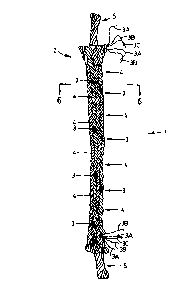
Referring to the embodiment shown in Figure 1, the
fence rope, generally indicated by 1, comprises an inner
core 5, and an outer braided jacket 2. Outer braided
jacket 2 encases inner core 5.
CA 02267771 1999-04-06
AMENDED SHEET
8
Inner core 5 is preferably constructed from multiple
strands of high tenacity fibres using conventional rope
making techniques. The strands may comprise extruded
monofilaments in flattened, square, oval, round or other
shapes, or yarns of twisted fibres, including fibres
formed from synthetic polymers such as polypropylene,
nylon ;polyamide) and polyester. The inner core can be
straight, or twisted or of braided construction.
As illustrated by the embodiments in Figures 1, 2
and 3, the braided elements making up the outer braided
jacket 2 may be of two types.
The first type of braided element, as at 3 in the
Figures, is an electrically conductive element comprised
of a single conductive element, or especially of a strand
of , _ _ , _ccnducti ve f; 1 cements, preferabl y twi sted together. A
very conductive element is copper, which is preferred,
but any one of a number of other highly conductive
elements may be used e.g. copper alloys, copper coated on
ar_cther metal, or copper with a coating of another metal,
as well as many other conductive metals. The conductive
element should exhibit relatively low electrical
resistance. The conductive elements may be combined with
non-conductive filaments, provided that the resultant
element in the braided exterior layer still serves the
purpose described herein of providing an electrical
charge on the exterior surface of the fence rope.
As is shown in Figure 1, not a11 of the strands in
the braided element 3 need to be conductive. For
example, those of 3A can be conductive and those of 3B
non-conductive. The remaining strand 3C is a coloured
tracer for visibility purposes. A similar coloured
strand or strands can also be included in the braid
element 4. Such coloured strands are optional.
The second type of braided element, as at 4, wculd
normally not contain any conductive filaments, but may do
so as discussed above. This type of braided element is
typically constructed from suitable strands of non-
CA 02267771 1999-04-06 ,~(V~Eiv~Cu jJ_=T
9
conductive fibres, which could be the same as, or
different from, those used in core 5. These braided non-
conductive elements may be coloured, or may include a
coloured tracer to increase visibility of the fence rope,
such coloured elements being optional.
Alternative constructions are shown ~.n Figures 2 and
3. In Figure 2, there is only one braided element 3 in
the outer jacket that includes conductive filaments. In
this construction, it is preferred that this single
conductive element be made entirely of conductive
filaments. In Figure 3, there are several braided
elements 3, and each may be made only of conductive
filaments or of a combination of both conductive and non-
conductive filaments. In either construction, there must
"e Suf: ~...=e':t cOndl;ct i ~rit~r t0 cort~a the pprpOSe Of the
,.,
electric fence rope.
The use of two conductive elements is the preferred
construction. The first conductive element of Figure 1 is
braided in a counter-clockwise helix, when viewed from
the bottcm of Figure 1. The second conductive element
would be braided in a clockwise helix. The remaining
non-conductive elements would be braided half in counter-
clockwise helix, and half in clockwise helix.
It will be appreciated that a variety of materials
may be used and that the construction of the rope of this
invention can vary. There are many materials which are
suited to be either the core or carrier materials, for
both the conductive and non-conductive filaments. Such
materials will be understocd by persons skilled in the
art.
As noted above, the conductive filaments are
preferably copper, as such filaments are good conductors
of electricity, are not readily corroded, and are readily
available. Other metals can also be used, examples of
which are disclosed herein. .
The non-conductive filaments can be chosen from a
wide range of synthetic polymer fibres. It is possible to
r-, r~~
CA 02267771 1999-04-06 --
;~ME~IOCLI J~CCT
10
use filaments conventionally used in the manufacture of
rope, either as monofilament or as a spun yarn. Preferred
materials are polypropylene, polyamides and polyesters,
as either monofilaments or spun yarns or co-extruded high
strength polypropylene and polyethylene as a monofilament
e.g. PolysteelTM monofilament. A preferred polyester
fibre is Allied Signal high tenacity yarn 1w70, which is
used in the manufacture of automotive seat belts. Seat
belts used in restraint systems must be .in compliance
with the high standards imposed thereon, including
strength, abrasion resistance, elongation,
colourfastness, and resistance to ultraviolet light and
microorganisms. The preferred fibre is 1,000 denier, and
has a specified breaking strength of 9.2 kg, tenacity of
i5 9.2 TSiderier, tC'aghnecc of n.,71 gmS~denlP_r and 13%
g
elongation at break. Denier is a measure of the weight of
a thread, and is defined as the weight in grams of a
9000m length of thread.
Other synthetic fibres may be used, including
Spectral" fibres of ultrahigh molecular weight
polyethylene, aramid fibres e.g KevlarTM and NomexT~ fibres
and DacronT~' polyester fibres, and other fibres noted
herein. It will also be appreciated that other synthetic
fibres may be used, depending on the proposed erd-use.
The double helix configuration of the conductive
element protects relatively low strength conductors, such
as copper, from tensional strain.. When strain is impcsed
on the fence rope, the fence rope will stretch but, as
the fence rope stretches, the copper conductor uncoils in
the manner of a coiled spring i.e. it uncoils in the
manner of a "Slinky"~ toy, with little longitudinal
tension on the copper wire itself. As tension increases,
the fibre elements in the outer braided jacket tend to
clamp onto the inner core, and the combination of forces
3S in the braided construction inhibits stretching of the
fence rope. The high strength non-conductive fibres,
CA 02267771 1999-04-06 A~~F_NDED SHEET
li
together with the braided construction, provide the fence
rope with inherent strength, while the copper conductors
provide an effecti~re electric shock.
In preferred embodiments of the fence rope of this
invention, the tendency of the relatively fragile copper
to break is preferably further reduced, first, by using a
substantially larger cooper wire than might otherwise be
used, such as 30 gauge, second, by using ten copper wires
of this large gauge instead of only a few copper wires of
smaller gauge, third, by twisting the copper wires into
strands ef five wires each because twisted strands are
stronger and tougher than individual wires, and fourth,
by placing the twisted copper wires into a suitable
helical configuration. The helix allows the copper
t., t,-, a ,- ~ a co; ~ od c ,
y~ conuac ,.~ ., c.. _ik a ___ spring, whi h simpl;
uncoils when the fence rope is tensioned, with very
little longitudir_al tension on the copper wires to cause
the wire to break, particularly when the elongation of
the fence rope is less than ten percent.
In preferred embodiments of the present invention,
the braided elements are formed on equipment used to
braid ropes for the marine yachting industry, e.g. for
sail halyards and spinnaker sheets.
The core, if present, may be fabricated by
conventional rope making techniques e.g. from any non-
conductive high tenacity filaments, and can be either
straight, twisted or braided. The fibres of the core may
be the same or differer_t from the fibres of the braided
exterior layer.
The conductive filaments are incorporated into the
braided elements in sufficient number to carry the
electric charge. If there is a single braided outer
layer, a plurality of conductive filaments e.g. flexible
metal filaments, will normally be required. The
conductive elements may be in one or preferably two of
the braided elements, although as discussed above more or
all of the braided elements could have conductive
CA 02267771 1999-04-06
AMENDED SHEET
12
elements. Each of such conductive braided elements may
conveniently contain at least one, and preferably
several, conductive filaments. Alternatively, one
braided element can be made up entirely of conductive
S filaments. If there is more than one braided Layer, at
least the outer layer must contain conductive elements.
One or more fluorescent elements, or one or more
light reflective elements, may be incorporated in the
braided outer jacket to impart greater visibility to the
fence rope in relative darkness or at night from the
light of the moon or from moving vehicles or from other
light sources. If desired, the high tenacity filaments in
the outer layer can be coloured with pigments, including
high visibility colours. The high tenacity filaments can
'~ , '~ ~ ~ ~ ~ d ua 2 fl a lit .. ~b r
a150 ue CaoS2W.0 prC'J.r,..,e a e'.~ t a~.~..''1 ~ ~ Si., Ze_O
temperature environments.
Field trials without electricity, and laboratory
break-strength tests, demonstrate that the double helix
construction of this braided fence rope protects the
conductive elements, including pure copper wire
conductors, from breaking despite the substantial forces
imposed on the fence by the largest domestic animals,
such as stallions and bulls, or by typical farm
operations.
2S The conductive elements of the electric fence rope
of this invention have been demonstrated in field trials
and. laboratory tests not to fatigue fracture or to work
harden and break, or to break from abrasion, when
installed as a permanent fence. Where the fence rope is
exposed to abrasion, only the outermost individual strand
or strands is subject to being broken. If one entire
twisted strand is broken, then the second twisted strand
of copper filaments on the opposite side of the fence
rope will likely remain intact and maintain conductivity.
If the entire fence rope is severed, it can be easily and
effectively repaired by inserting both ends of the fence
rope into a short piece of copper tubing of slightly
CA 02267771 1999-04-06
AMENDED S1;E~T
13
larger inside diameter than the outer diameter of the
fence rope, and crimping, or by using a copper or other
metal clamp, or by a copper or other metal U-bolt.
Due to the braided construction and the availability
S of high strength synthetic fibres, such as polyester, the
braided fence rope of this invention can maintain its
dimensional stability, in particular, its length, without
sagging or becoming slack, notwithstanding temperature
changes, wind, snow, and ice, and the typical animal
impacts and forces imposed in normal farm operations.
In one aspect of the invention, the electric fence
rope is designed for minimum stretch and creep. In
another aspect, the electric fence rope is designed for
significant elasticity. In the first aspect, the non-
conductive elements cf the inner core are selected for
treir dimensional stability and relative in-elasticity.
In the second aspect, the non-conductive elements in the
inner core are selected for their elasticity, and the
braided construction design selected for the outer jacket
will be a tightly coiled helix in the outer coil that
will simply expand by uncoiling, allowing the braided
jacket to stretch without imposing excessive tensional
strain on the conductive elements in the braided jacket.
In a preferred embodiment, the conductive elements
are strands of multiple filaments of wire, such as pure
copper, and the non-conductive elements in the outer
layer are fibres selected for their resistance to
abrasion, to ultraviolet light, and to chemical attack,
e.g. polyester.
In an embodiment of the invention, there is no inner
core. Such an embodiment may be used especially if the
outer layer is constructed tightly or if the fence rope
is of smaller diameter overall. Inner cores and outer
braided layers add tensile and/or breaking strength to
the rope, especially if required for certain end-uses.
For operation, the rope may be connected to a
standard electric fence charger, properly grounded, using
.-'T
CA 02267771 1999-04-06
;~,'y'~~:~rJ J~'1C:.;
14
appropriate clamps or connectors. The rope may be added
to existing fences, e.g. using conventional electric
fence insulators; or used as the sole fencing material.
Conventional electric fence insulators may be used, as
required. It may be used in single rope, mufti-rope or
other construction, as required. It has the strength to
be used alone, or in mufti-rope configurations, with
large animals e.g. horses and cattle.
The fence rope of this invention may be conn~c~ed by
knotting cr crimping or fastening lengths with wire
clamps or fasteners, to form loosely or tightly woven
nets which can be electrified for more secure control of
ar_imals, especially animals smaller than horses or
cattle, including deer, rabbits or fox, and even
squirrels. The holes.formed by the nets may be
rectangular, hexagonal or other shapes.
The materials and the design used for the electric
fence rope of this invention may be selected from a
number of alternatives for each of many, varied fence
rea_uirements, including varying the shape, size and
construction: of each of the elements and the overall
diameter and weight of the fence rope. The braid
configuration can be a tightly coiled helix, like a
coiled spring, or a long, open helix, like an open
spring. The inner core can be braided fibres, straight
fibres or twisted fibres, or the inner core may be
omitted. The materials selected for the inner core may
be dimensionally very stable or elastic. One or more
braided jackets may be used, and these may be braided
integrally together for increased strength, with the
electrically conductive elements in the exterior layer.
The fence rope is relatively soft, flexible, and
light weight; it resists rot, mildew, W, or chemical
breakdown, and can be coloured to make it highly visible.
Tt is of very high strength and has proven in testing. to
contain animals without electric shocks. It has been
tested in areas where some fence posts are up to 50
CA 02267771 1999-04-06 ;1 ;'; y J = ;. ,y; - .-
15
meters apart, thus saving on the cost of posts, equipment
and labour. As a consequence of the softness and
flexibility of the rope, animals which run into it are
normally not harmed. Cn such an impact the fence rope is
sufficiently resilient to not cut, and it subsequently
returns to essentially its original length. Due to the
braided construction, the fence rope does not sag or
become slack under applied tension, as occurs with
twisted materia~..~. As the tension increases the outer
braided elements tend to clamp onto the inner core,
thereby inhibiting any stretching by the inner core.
Twisted materials tend to stretch when tension is
applied due to the fact that they "unlay", and have a
tender_cy to become straight, losing strength in the
process. More and more tension is required to keep
twisted materials tight, and this causes problems in
keeping fence posts in place. The fence rope of this
invention does not require as much tension to keep it
taut, and does not tend to elongate under tension, thus
reducing maintenance.
The braided electric fence rope of this invention
has strength and resilience to permit spacing fence posts
at greater distances apart. Any impact of an animal
collision is absorbed by the fence rope, similar to ropes
in a boxing ring, and the animal is normally restrained
without the fence rope breaking or the animal being hurt.
Although an animal may chew it, the animal will not do so
if the fence is electrified. As a result of resilience to
contain an animal, and being electrified, the fence rope
of the invention does not have to be tightened
mechanically, but may be tightened by hand using a rope
ratchet or manual fence tightener.
The present invention is illustrated as follows:
A S/16 inch (8 mm) diameter braided rope was
produced on an 8 carrier braiding machine at 5 picks per
inch (2 picks/cm). The non-conductive elements were
comprised of several flattened monofilaments of
CA 02267771 1999-04-06 AM ENDED SHEET
16
PolysteelT'", a trade name for co-extruded high strength
polypropylene and polyethylene, gathered into 7 non-
conductive elements. Other monofilaments with similar
properties are available under the trade-marks Garfil
Maxi maT'" and DanlineT'". A single conductive a 1 ement having
six ends of tin-coated copper wire in a twisted strand
was braided in a counter clockwise helix. The inner core
was formed in a straight configuration from the same co-
extruded monofilaments as the outer braided jacket in an
amount sufficient to fill the hollow care in the braided
jacket. The breaking strength of rope of this
construction was in the range of 1,000 to 1,S00
kilograms.
Another rope was produced as a rope fence for use
wi th horses and for. rotati or_a1 grazi r_g. It was 1 /4 ir_ch
i~.3 mm) diameter braided rope produced on a 16 carrier
braiding machine at 8 picks per inch. The non-conductive
elements in the outer braided jacket were comprised of
spun 1W70 polyester fibres manufactured by Allied Signal
for automotive seat belts, twisted into strands.
Polyester fibres are soft, and W and abrasicn resistant.
The conductive elements were two twisted strands of 5
ends each of pure copper wire. The two conductive
elements were braided with 14 non-conductive elements
into helix configurations, clockwise and
counterclockwise. The non-conductive fibre elements were
given an S-twist or a Z-twist to provide a smooth outer
lay with all.fibres aligned along the braided rope. The
rope had an inner core of spun fibres of multi-filament
polypropylene in a slightly twisted configuration filling
the hollow core of the braided jacket. The breaking
strength of this construction was in the range of 500 to
700 kilograms.
Accelerated Weathering Testing (ASTM G 53-96) showed
no indication of product degradation during l,000 hours
of testing other than a slight yellowing. There was no
cracking, no fraying, no indication of mould or fungus
CA o2267771 1999-o4-ob AM ENDED SHEET
17
growth, no corrosion of the copper, and no significant
loss of strength in periodic break tests. Field tests
have shown no breakage or loss of electrical conductivity
in normal farm operations due to abrasion, work
S hardening, or tensional forces and no harm or damage of
any kind to animals.
Another rope was a 3/8 inch (9.5 mm) diameter fence
rcpe for the purpose of keeping moose off highways to
reduce mcose - vehicle collisions. It had a braided
polyester outer jacket with a braided inner sleeve of
PoiysteelT~ monofilaments, surrounding straight
PolysteelTM monofilaments, fully integrated during
braiding in a so-called double braid construction. The
outer braided jacket incorporated reflective light fibres
and fear copper c~nductive elements of twisted 30 gauge
wires. The break test of this heavier fence rope was
almost 2,000 kilograms.
In another example, a 1/8 inch (3.2 mm) diameter
electric fence rope was produced on an 8 carrier braiding
machine with a parallel-laid core. The braided jacket had
polyester fibres and the core had mufti-filament
polypropylene fibres. Two strands of three ends each of
34 gauge copper wire were braided into the outer jacket
in opposed helical configurations. Such a fence rope is
intended for use with an existing fence, and has a break
test strength cf 200 kilograms.
The braided electric fence rope of this invention
can be used to construct an electric fence that combines
both the psychological deterrence of an electric shock
with the strength and resilience to withstand applied
force by animals. Embodiments of the fence rope of this
invention have many added advantages: it is easy to
install and to maintain; it is light weight; it is
portable and flexible when needed; it reduces or
eliminates disadvantages of electric high tensile wire
e.g. as enumerated above or. page 2; it may be made
visible to animals; it does not cut the flesh of animals,
CA 02267771 1999-04-06 A MENDED SHE~T
18
or cause puncture wounds; and it may be manufactured and
installed economically.
In embodiments, fencing made from the rope of the
invention is easy to handle, may be run longer distances
between posts, is flexible and has little stretch. It
will not harm animals running into it, but it is strong
enough to withstand that. The fence rope does not chafe,
it does not crack or peel, and does not sag or break
under wind and ice. It may be made highly visible
against varied backgrounds, including snow and low light
conditions, and especially against dark backgrounds e.g.
wooded areas and to some extent at night. rencing may be
installed over varied terrain with a minimum of effort.
After installation, the fence should not need re-
tightening ~n~l it dnec not need t0 be Checked fOr
- . . r
breakage after wind storms. Snow and ice tend to fall
off as soon as there is a light breeze.
CA 02267771 1999-04-06
..r, r.rn L~~
~ YSI~~/IC~'~I~JLJ UI tCVT