Language selection

Search

Patent 2267781 Summary

Third-party information liability

Some of the information on this Web page has been provided by external sources. The Government of Canada is not responsible for the accuracy, reliability or currency of the information supplied by external sources. Users wishing to rely upon this information should consult directly with the source of the information. Content provided by external sources is not subject to official languages, privacy and accessibility requirements.

Claims and Abstract availability

Any discrepancies in the text and image of the Claims and Abstract are due to differing posting times. Text of the Claims and Abstract are posted:

  • At the time the application is open to public inspection;
  • At the time of issue of the patent (grant).
(12) Patent: (11) CA 2267781
(54) English Title: PATH TO PROVIDE OTDR MEASUREMENTS OF AN OPTICAL TRANSMISSION SYSTEM THAT INCLUDES OPTICAL ISOLATORS
(54) French Title: CIRCUIT POUR MESURES PAR REFLECTOMETRIE OPTIQUE TEMPORELLE D'UN SYSTEME DE TRANSMISSION OPTIQUE COMPORTANT DES ISOLATEURS OPTIQUES
Status: Expired and beyond the Period of Reversal
Bibliographic Data
(51) International Patent Classification (IPC):
  • G01M 11/00 (2006.01)
(72) Inventors :
  • KIDORF, HOWARD D. (United States of America)
(73) Owners :
  • TYCO ELECTRONICS SUBSEA COMMUNICATIONS LLC
(71) Applicants :
  • TYCO ELECTRONICS SUBSEA COMMUNICATIONS LLC (United States of America)
(74) Agent: KIRBY EADES GALE BAKER
(74) Associate agent:
(45) Issued: 2007-07-10
(86) PCT Filing Date: 1997-10-15
(87) Open to Public Inspection: 1998-04-30
Examination requested: 2002-09-27
Availability of licence: N/A
Dedicated to the Public: N/A
(25) Language of filing: English

Patent Cooperation Treaty (PCT): Yes
(86) PCT Filing Number: PCT/US1997/018578
(87) International Publication Number: US1997018578
(85) National Entry: 1999-04-06

(30) Application Priority Data:
Application No. Country/Territory Date
08/740,042 (United States of America) 1996-10-23

Abstracts

English Abstract


A path couples a pair of optical fibers in an optical transmission system. The
transmission system includes a plurality of optical
amplifiers (17, 18) placed along the transmission line (10, 12). Associated
with these optical amplifiers are optical isolators (21) that limit
the flow of optical energy to a single direction. The path allows reflected or
scattered light from one optical fiber after the optical isolator
to be returned via the other optical fiber. This enables an OTDR device to
obtain measurement information along the length of the fibers
between optical isolators (21).


French Abstract

Circuit reliant deux fibres optiques dans un système de transmission optique. Le système de transmission comporte une pluralité d'amplificateurs optiques (17, 18) placés le long de la ligne de transmission (10, 12). Des isolateurs optiques (21) associés à ces amplificateurs optiques limitent le flux d'énergie optique à une seule direction. Le circuit permet de renvoyer la lumière réfléchie ou dispersée provenant d'une fibre optique après un isolateur optique, via l'autre fibre optique. Ce procédé permet à un dispositif de réflectométrie optique temporelle d'obtenir des informations de mesure sur toute la longueur des fibres entre les isolateurs optiques (21).

Claims

Note: Claims are shown in the official language in which they were submitted.

7
CLAIMS
1. An optical transmission system comprising:
a first optical fiber, said first optical fiber
having an input and an output;
a second optical fiber, said second optical fiber
having an input and an output;
a third optical fiber, said third optical fiber
having an input and an output;
a fourth optical fiber, said fourth optical fiber
having an input and an output;
a first optical isolator coupled to said output of
said first optical fiber, said first optical isolator
having an input and an output;
a second optical isolator coupled to said output of
said third optical fiber, said second optical isolator
having an input and an output;
an optical coupler having four ports and coupled to
the output of said first optical isolator, the input of
said second optical fiber, the output of said second
optical isolator, and the input of said fourth optical
fiber;
a first path through said optical coupler coupling
the input of said first optical fiber to the input of
said second optical fiber;
a second path through said optical coupler coupling
the input of said second optical fiber to the input of
said fourth optical fiber;
a third path through said optical coupler coupling
the input of said third optical fiber to the input of
said fourth optical fiber;

8
a fourth path through said optical coupler coupling
the input of said fourth optical fiber to the input of
said second optical fiber; and
a first transmission path for carrying optical
communication signals in a first direction and a second
transmission path for carrying optical signals in a
second direction, said first transmission path including
said first and second optical fibers, and said second
transmission path including said third and fourth optical
fibers;
said optical coupler being operative to couple
backwards propagating optical energy received from the
first transmission path to the second transmission path
and to couple backwards propagating optical energy
received from the second transmission path to the first
transmission path, whereby optical energy coupled by said
optical coupler may be analyzed to locate faults along at
least one of the first and second transmission paths.
2. The optical transmission system of claim 1, further
comprising:
a first optical amplifier disposed on said first
transmission path; and
a second optical amplifier disposed on said second
transmission path.
3. The optical transmission system of claim 2, wherein
said first and second optical amplifiers are remote
optical amplifiers.

9
4. The optical transmission system of claim 2, wherein
said first and second optical amplifiers are within a
repeater.
5. The system of claim 1, wherein said second path
supports a returning OTDR signal to said first
transmission path and said fourth path supports a
returning OTDR signal to said second transmission path.
6. The system of claim 1, said system further
comprising:
at least one first transmission path optical
isolator disposed along said first transmission path,
each of the first transmission path optical isolators and
said first optical isolator being operative to propagate
light in said first direction and to substantially
prevent propagation of light in said second direction to
thereby direct signals transmitted on said first
transmission path in said first direction;
at least one second transmission path optical
isolator disposed along said second transmission path,
each of the second transmission path optical isolators
and said second optical isolator being operative to
propagate light in said second direction and to
substantially prevent propagation of light in said first
direction to thereby direct signals transmitted on said
second transmission path in said second direction; and
at least one additional optical coupler, each
respective additional optical coupler receiving optical
input from a corresponding one of the first transmission
path optical isolators and a corresponding one of the

second transmission path optical isolators and being
operative to couple backwards propagating optical energy
received from the first transmission path to the second
transmission path and to couple backwards propagating
optical energy received from the second transmission path
to the first transmission path, whereby optical energy
coupled by each said additional optical coupler may be
analyzed using OTDR to locate faults along at least one
of the first and second transmission paths.
7. The system of claim 6, further including a housing
containing a respective one of said additional optical
couplers or said optical coupler, a portion of each of
said first and second transmission paths, a corresponding
one of said first transmission path optical isolators or
said first optical isolator, and a corresponding one of
said second transmission path optical isolators or said
second optical isolator.
8. The system of claim 7, wherein said housing further
contains first and second optical amplifiers disposed
along said first and second transmission paths,
respectively.
9. The system of claim 8, wherein said first and second
optical amplifiers are remotely pumped from a location
external to said housing.

Description

Note: Descriptions are shown in the official language in which they were submitted.


CA 02267781 1999-04-06
WO 98/18224 PCTIUS97/18578
PATH TO PROVIDE OTDR MEASUREMENTS OF AN OPTICAL
TRANSMISSION SYSTEM THAT INCLUDES OPTICAL ISOLATORS
BACKGROUND OF THE INVENTION
The present invention is directed to a path between
a pair of fibers in an optical fiber transmission system.
More particularly, the present invention is directed to a
path that allows Optical Time-Domain Reflectometry ("OTDR")
measurements of an optical fiber transmission system that
includes repeaters and optical isolators.
An OTDR is a fiber-optic measurement instrument. An
OTDR operates by sending a probe signal down a fiber and
monitoring the small fraction of the light scattered or
reflected back to it. The reflected light can be used to
determine if there is a fault in the fiber.
A typical long range optical transmission system
includes a pair of unidirectional optical fibers. An
optical signal attenuates over long distances. Therefore,
the optical fibers typically include multiple repeaters
spaced apart. The repeaters include optical amplifiers
that amplify incoming attenuated optical signals. The
repeaters also include an optical isolator that limits the
propagation of the optical signal to a single direction.
A typical long range optical transmission system
requires atechnique for determining the location of
faults along the transmission path using only equipment
located at the ends of the transmission system. Two
techniques are in common use: loopback and OTDR.

CA 02267781 1999-04-06
WO 98/18224 PCT/US97/18578
- 2-
The loopback technique operates by placing a coupling
in the repeater so that a portion of the signal from one
direction is coupled into the opposite direction. The
return signal is then analyzed by equipment at the end of
the transmission system to detect the magnitude of the
returns from each of the repeaters.
It is known that modifications to a transmission
system are required to permit the OTDR technique. This is
due to the unidirectional behavior of the optical isolator
that eliminates the scattered and reflected light in the
return direction. To make use of the OTDR, the paired
transmission line is used to carry the returned light. A
coupling is provided in each repeater to accomplish this.
Fig. 1 illustrates a known arrangement that is used
to implement the coupling required by both the loopback
and OTDR techniques. The segment of an optical
transmission system in Fig. 1 includes fibers 10, 12 on
which the optical signals travel in the direction
indicated by the arrows. Multiple repeaters are disposed
along the fibers 10, 12. Two such repeaters 14, 16 are
shown in Fig. 1. Repeaters are typically spaced 30 to 120
km apart.
Repeater 14, which is typical of all of the repeaters
along the fibers 10, 12, is shown in detail in Fig. 1.
Repeater 14 includes optical amplifiers 17, 18 which
amplify the optical signal along the transmission line.
Typical optical amplifiers are constructed with an erbium
doped fiber that is pumped by a laser source. Optical
isolators 21, 25 are required in long transmission spans
to eliminate backwards propagating light and to eliminate
multiple path interference.
The coupler arrangement shown inside repeater 14
provides the path required for both fault location
techniques. These paths are implemented with couplers 30,

CA 02267781 1999-04-06
WO 98/18224 PCT/US97/18578
- 3-
40, 50 and 60. This coupler arrangement provides loopback
and OTDR paths for both optical fibers 10 and 12.
Transmission on optical fiber 10 can be used as an
example. The signal follows the loopback path through
couplers 30, 50 and 60 on the following fibers: 31-34-53-
51-63-62. The looped back signal then travels along with
the data on transmission path 12. Typically the looped
back signal is attenuated by about 45 dB relative to the
signal present on fiber 31.
The coupler arrangement also implements a path for
use by the OTDR. Signals generated by reflection or
scattering between repeaters 14 and 16 enter coupler 30 on
fiber 32. The signal follows the following fibers: 32-33-
41-42-52-51-63-62. The signal then travels along with the
data on transmission path 12. Typically the OTDR signal
is attenuated by about 20 dB relative the signal present
on fiber 32.
Similar paths are taken by signals traveling on
optical fiber 12.
Amplification schemes other than that shown in Fig.
1 have recently been developed. These systems use remote
amplifiers that do not require electrical power. An
example of such a system is illustrated in Fig. 2 in which
amplifiers 76, 79, 83, 86 are disposed on the transmission
paths 90, 91 between two repeaters 70, 72. The power for
the amplifiers 76, 79, 83, 86 is delivered optically
either through the use of dedicated pump fibers 75, 80 or
through a portion of the transmission paths 91, 90.
Isolators 66, 77, 78, 68, 69, 81, 82, 67 are required to
eliminate backwards propagating light and to eliminate
multiple path interference. Unfortunately, these
isolators eliminate the reflections caused in transmission
fibers 58, 84, 91, 59, 85, 90. This makes the OTDR
technique for fault location impossible. Further it is
undesirable to place an entire coupler arrangement,

CA 02267781 1999-04-06
WO 98/18224 PCTIUS97/18578
- 4-
including couplers 30, 40, 50, 60 shown in Fig. 1 at the
location of the remote amplifiers because using a
mechanical housing of sufficient size to accommodate all
four couplers is expensive and undesirable.
SUMMARY OF THE INVENTION
The present invention is a path that couples a pair
of optical fibers in an optical transmission system. The
transmission system includes a plurality of optical
amplifiers placed along the transmission line. Associated
with these optical amplifiers are optical isolators that
limit the flow of optical energy to a single direction.
The path allows reflected or scattered light from one
optical fiber after the optical isolator to be returned
via the other optical fiber. This enables an OTDR device
to obtain measurement information along the entire length
of the fibers between optical isolators.
BRIEF DESCRIPTION OF THE DRAWINGS
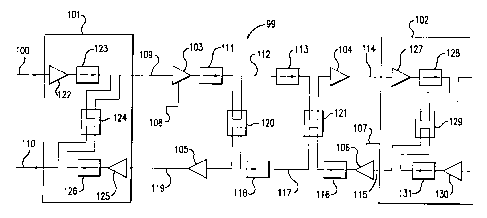
Fig. 1 illustrates a segment of a repeatered optical
transmission system that can be used with an OTDR.
Fig. 2 illustrates a segment of a repeatered optical
transmission system that includes remote amplifiers.
Fig. 3 illustrates a segment of a repeatered optical
transmission system that includes remote amplifiers and
the present invention.
DETAILED DESCRIPTION
The invention will be described in connection with an
exemplary optical transmission system that includes
repeaters, remote amplifiers and optical isolators. The
invention is,a path within such a transmission system that
allows OTDR measurements along the entire length of the
optical fibers between the optical isolators. The
invention may also be applied to transmission systems that

CA 02267781 1999-04-06
WO 98/18224 PCT/US97/18578
- 5-
do not make use of remote amplifiers such as that shown in
Fig 1.
Fig. 3 illustrates a segment of an optical
transmission system that includes repeaters, remote
amplifiers and the present invention. The optical
transmission system 99 includes a pair of optical fibers
100, 110 on which optical signals travel in the direction
indicated by the arrows. Multiple repeaters are placed
along the fibers 100, 110. Two such repeaters 101, 102 are
shown in Fig. 3.
The repeater configuration and remote amplifiers are
similar to those shown in Fig. 2. The transmission system
99 includes multiple remote amplifiers 103-106 that are
external to the repeaters 101, 102. The repeaters 101,
102 include amplifiers 122, 125, 127, 130. The power for
amplifiers 103, 106 is delivered optically through
dedicated pump fibers 108, 107, respectively. The power
for amplifiers 104, 105 is delivered through transmission
paths 114, 119, respectively. Isolators 123, 111, 113,
128, 131, 116, 118, 126 are required to eliminate
backwards propagating light and to eliminate multiple path
interference.
Because of the presence of the optical isolators in
transmission system 99, an OTDR-based fault locator would
not normally provide measurement information for the
optical transmission path past the first optical isolator
on the transmission path.
In order to allow OTDR measurements on the
transmission system 99, a path must be provided for the
reflected and scattered light from transmission fibers
109, 112, 114, 115, 117, 119 to be returned to the source
of the OTDR probe signal. The present invention provides
this path for the return signal at all locations where it
is required by using optical couplers 124, 120, 121, 129.

CA 02267781 1999-04-06
WO 98/18224 PCT/US97/18578
- 6-
For example, a probe signal entering the optical
transmission system 99 on transmission fiber 100, and
reflected from transmission fiber 112, would be returned
on transmission fiber 110 via coupler 120. Similarly, a
probe signal entering this representative portion of the
transmission system on transmission fiber 110, that is
reflected from transmission fiber 119, for example, would
be returned on transmission fiber 100 via coupler 120.
The present invention can be used with an optical
transmission system with remote amplifiers to enable the
return of the OTDR signal from the entire length of the
transmission path between the repeater regardless of the
presence of the optical isolators. The present invention
may also be applied to a transmission system that has no
remote optical amplifiers by, for example, placing the
optical coupler inside of the repeater housing similar to
the optical coupler 124 in repeater 101 in Fig. 3.
What has been described is merely illustrative of the
application of the principles of the present invention.
Other arrangements and methods can be implemented by those
skilled in the art without departing from the spirit and
scope of the present invention.

Representative Drawing
A single figure which represents the drawing illustrating the invention.
Administrative Status

2024-08-01:As part of the Next Generation Patents (NGP) transition, the Canadian Patents Database (CPD) now contains a more detailed Event History, which replicates the Event Log of our new back-office solution.

Please note that "Inactive:" events refers to events no longer in use in our new back-office solution.

For a clearer understanding of the status of the application/patent presented on this page, the site Disclaimer , as well as the definitions for Patent , Event History , Maintenance Fee  and Payment History  should be consulted.

Event History

Description Date
Time Limit for Reversal Expired 2015-10-15
Letter Sent 2014-10-15
Inactive: IPC expired 2013-01-01
Letter Sent 2010-06-04
Grant by Issuance 2007-07-10
Inactive: Cover page published 2007-07-09
Pre-grant 2007-04-16
Inactive: Final fee received 2007-04-16
Notice of Allowance is Issued 2006-10-31
Letter Sent 2006-10-31
Notice of Allowance is Issued 2006-10-31
Inactive: Approved for allowance (AFA) 2006-10-23
Amendment Received - Voluntary Amendment 2006-08-21
Inactive: S.30(2) Rules - Examiner requisition 2006-02-20
Letter Sent 2004-02-04
Letter Sent 2002-10-31
Request for Examination Received 2002-09-27
Request for Examination Requirements Determined Compliant 2002-09-27
All Requirements for Examination Determined Compliant 2002-09-27
Amendment Received - Voluntary Amendment 2002-09-27
Letter Sent 2002-09-13
Inactive: Cover page published 1999-06-22
Inactive: First IPC assigned 1999-05-20
Inactive: IPC assigned 1999-05-20
Inactive: Notice - National entry - No RFE 1999-05-06
Application Received - PCT 1999-05-05
Application Published (Open to Public Inspection) 1998-04-30

Abandonment History

There is no abandonment history.

Maintenance Fee

The last payment was received on 2006-09-25

Note : If the full payment has not been received on or before the date indicated, a further fee may be required which may be one of the following

  • the reinstatement fee;
  • the late payment fee; or
  • additional fee to reverse deemed expiry.

Patent fees are adjusted on the 1st of January every year. The amounts above are the current amounts if received by December 31 of the current year.
Please refer to the CIPO Patent Fees web page to see all current fee amounts.

Owners on Record

Note: Records showing the ownership history in alphabetical order.

Current Owners on Record
TYCO ELECTRONICS SUBSEA COMMUNICATIONS LLC
Past Owners on Record
HOWARD D. KIDORF
Past Owners that do not appear in the "Owners on Record" listing will appear in other documentation within the application.
Documents

To view selected files, please enter reCAPTCHA code :


To view images, click a link in the Document Description column. To download the documents, select one or more checkboxes in the first column and then click the "Download Selected in PDF format (Zip Archive)" or the "Download Selected as Single PDF" button.

List of published and non-published patent-specific documents on the CPD .

If you have any difficulty accessing content, you can call the Client Service Centre at 1-866-997-1936 or send them an e-mail at CIPO Client Service Centre.


Document
Description 
Date
(yyyy-mm-dd) 
Number of pages   Size of Image (KB) 
Representative drawing 1999-06-16 1 5
Description 1999-04-05 6 265
Abstract 1999-04-05 1 46
Claims 1999-04-05 2 53
Drawings 1999-04-05 3 44
Claims 2006-08-20 4 132
Representative drawing 2006-10-25 1 9
Notice of National Entry 1999-05-05 1 194
Courtesy - Certificate of registration (related document(s)) 1999-05-05 1 116
Reminder - Request for Examination 2002-06-17 1 128
Acknowledgement of Request for Examination 2002-10-30 1 176
Commissioner's Notice - Application Found Allowable 2006-10-30 1 161
Maintenance Fee Notice 2014-11-25 1 170
PCT 1999-04-05 3 120
PCT 1999-07-12 3 121
Correspondence 2007-04-15 1 46