Note: Descriptions are shown in the official language in which they were submitted.
CA 02267787 2005-11-04
29758-1
BACKGROUND OF THE INVENTION
The invention relates to a screw closure with a securitv and guarantee strip,
for bottles.
Securitv and -uarantee strips today are formed on most screw closures in order
to indicate the first openinQ
of the bottle and to prevent that bv unauthorised persons, the contents of the
bottle may be contaminated. The
security strips consist of a cylinder-jacket shaped section which is connected
to the lower edge of the jacket of the
screw closure via connecting webs. The strips on their circumference mav
comprise weakened regions which tear on
opening for the first time. The strip sections remain connected to the screw
closure. They may however be
manufactured as one-piece and remain after the opening for the first time
below a retaining rib located axialy below
the thread on the bottle neck. With the conventiohal security and guarantee
strips either on the lower edge of these or
on their inner surface distributed over the circumference and protruding into
the clear cross secrion there are
arranged a multitude of
retaining cams distributed over the circumference (US-A-4,846,361). On
screwing on the lid at the bottler these
retaining cams slide over the retaining rib and latch under this. On opening
the screw closure the security strip is
retained by the retaining cams which above comprise a retaining surface and
the connecting webs between the screw
closure and the security strip break. On screwing on or placing on the lid of
the screw closure at the bottler, by way
of the resistance of in each case simultaneously four retaining cams, which
occurs when the cam passes over the
retaining rib, by way of the large spreading, problems may occur and the
safety strip may if it is manufactured
obliquely be pressed and jammed between the bottle neck and the jacket of the
screw closure. The security strip or
the connecting webs for the closure may already tear on the closure procedure.
The security strip with this loses its
purpose. With high output bottling plants a defect of the mentioned type may
lead to a stoppage of the whole plant.
But also on opening the screw lid the known security strips often tear only on
one side or are partly pushed
out bevond the retaining rib. On reclosing, the security strip jams between
the bottle neck and the jacket of the screw
closure, so that a sealed reclosure is not possible when previously the
security strip has not been removed by hand or
pushed back.
FR-A-2 682 357 mentioned in the Intemational Search Report comprises two
groups of retaining cams
borderine one another, of differing heights, by which means the oblique
position of the
securitv strip is actually encouraged.
1
CA 02267787 2005-11-04
29758-1
BRIEF SUMMARY OF THE INVENTION
The object of the present invention was to provide
a security strip which at the bottler or high output
bottling machines may be deposited onto the bottle without
trouble and which on opening the bottle by the consumer
separates perfectly from the screw closure and remains back
below the retaining rib on the bottle neck or with
returnable bottles tears and remains connected to the screw
closure.
In accordance with one aspect of the present
invention there is provided a screw closure with a security
and guarantee strip for bottles, with which an annularly
formed security strip is connected to a jacket of the screw
closure by webs and on an inner surface of the security
strip carries retaining cams protruding into a clear cross
section, wherein a first pair of retaining cams lying
diagonally opposite one another and at least one further
retaining cam displaced by approximately 900 and axially
displaced by a predetermined amount are arranged on the
security strip.
This object is achieved by a security and
guarantee strip according to the features of patent claim 1.
The retaining cams arranged axially displaced on
placing on the lid effect considerably lower spreading
forces onto the security strip and prevent the premature
destruction of this.
la
CA 02267787 1999-04-06
Two retaining cams arranged in pairs and axially displaced to one another, on
screwing on the screw lid,
likewise slide after one another over the retaining rib, by which means the
security strip on account of the oval
deformation is hardly stretched and a slight axial pressing force is necessary
in order to permit the jumping over of
the retaining rib. On opening the bottle firstly the two upper-lying holding
cams are held back by the retaining rib
and here only tensile forces occur on the connecting webs which are preferably
formed laterally to the retaining
cams, and tear through these. As soon as the first connecting webs are torn
the next retaining cams get to the
retaining rib and tear through the neighboring connecting webs. An oblique
position of the security strip is avoided
by way of this and if formed as one piece it always stays back below the
retaining rib on the bottle neck. A security
strip with a predetermined breaking location and a connection to the screw
closure remains connected to the latter.
BRIEF DESCRIPTION OF THE DRAWINGS
The invention is hereinafter described by way of an embodiment example. There
are shown:
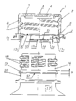
Figure 1 an axial cross-section through a screw closure with a security and
guarantee strip as well as below, the neck
of a PET bottle,
Figure 2 a cross section along line ll-II between the lower edge of the jacket
of the screw closure and the upper edge
of the security strip,
Figure 3 a cross section along line Il-II through the security strip in Figure
I during the screwing on of the lid,
Figure 4 a perspective representation of the closure unit according to Figures
1-3,
Figure 5 a cross section along line III-III between the lower edge of the
jacket of the screw closure and the upper
edge of the security strip in Figure 6,
Figure 6 a perspective representation of a further formation of the invention
with a connected security strip.
DETAILED DESCRIPTION OF THE INVENTION
In the Figures 1 and 2 with the reference numeral I there is schematically
shown a closure unit consisting of
a screw closure 2 and a security strip 3. The closure unit I consists of
thermosplastic plastic and is manufactured by
injection moulding. The screw closure 2 comprises a base 4 on which a sealing
rib 5 running concentrically to the
symmetry axis A may be mounted. To the base 4 there connects a jacket 6 which
on its inner side preferably in
sections carries apportioned thread windings 7. The formation of the screw
closure 2 is generally known and here is
not described in more detail. The seceurity and gurantee strip 3 is connected
to the lower edge 8 of the jacket 6 of the
screw closure 2 by very thin webs 9 of few tenths of a millimeter thick. The
length of the connecting webs 9 or the
Z
CA 02267787 1999-04-06
distance between the upper edge 10 of the security strip is very small and
lies in the size order of a few tenths of a
millimetre.
On the inner jacket surface 1 I of the security strip in the example shown
there are formed two pairs of
retaining cams 12a, 12b; 13a, 13b. The retaining cams 12a and 12b as well as
the retaining cams 13a and 13b lie
diagonally opposite, are displaced by approx 90 and are axially, i.e. with
respect to the axial extension of the
security strip 3, displaced by an amount a. The retaining cams 12a and 12b as
a result lie closer to the lower edge 14
of the security strip 3 than the retaining cams 13a and 13b by the amount a.
The distance a is preferably smaller than
the height b of a circumferential retaining rib 15 on the neck 16 of a bottle
17 e.g. manufactured from PET. On the
neck 16 of the bottle 17 there are visible thread sections 18 prodruding
outwardly from the bottle neck 16, these
being envisaged for coming into engagement with the corresponding thread
sections 7 on the inner side of the jacket
6 of the screw closure 2.
The connecting webs 9 lie, observed in the circumferential direction, between
the retaining ribs 12a, 12b;
13a, 13b. Alternatively to the webs 9 also film-like connections may hold
together the screw closure 2 and the
security strip 3.
The functioning manner of the security strip 3 of the first embodiment example
is subsequently explained
by way of Figure 3. On closing the bottle 17 with the closure unit 1, the
latter is placed from above axially onto the
bottle neck 16, and seen from above, is rotated clockwise. With this firstly
the thread sections 7 on the screw closure
2 come into engagement with the thread sections 18 on the bottle neck 16. On
further rotation and by way of this
axial advance of the closure unit I the two retaining cams 12a and 12b are
pressed radially outwards and
simultaneously the two retaining cams 13a and 13b displaced by approx. 90 are
pulled inwards. The security strip 3
with this assumes an oval shaping and stretches only extremely slightly and at
the most within the elasticity limit. As
soon as the two apexes Si on the retaining cams 12a and 12b as well as the
apex S2 on the retaining rib 15 have slid
over one another, the two retaining cams 12a and 12b are again pulled radially
inwards since at this moment the two
retaining cams 13a and 13b arranged axially displaced now also come into
contact with the retaining rib 15 and
analogously to the two other ribs are forced radially outwards. With this the
cross section of the security strip 3
becomes oval again. Already after a short time also the two retaining cams 13a
and 13b slide over the retaining rib
15 and thereafter are located, as also the two retaining cams 12a and 12b, in
the cylindrical region 20 of the bottle
neck. On closing the bottle 16 the thin connecting webs 9 are only slightly
mechanically loaded, since by way of the
axial pressure the security strip 3 with its upper edge 10 bears on the lower
edge 8 of the jacket and the connecting
webs 9 at the same time are only squeezed.
On opening the screw closure firstly the two retaining cams 13a and 13b lying
diagonally opposite one
another come into contact with the retaing rib 15 on the bottle neck 16. Since
however neither on the retaining cams
13a and 13b nor on the retaining rib 15 do inclined surfaces meet one another
and permit a pushing apart of the two
parts as with screwing on or on closing, but the retaining rib 15 does not let
past the retaining cams 13a and 13b, the
latter are held back and the connecting webs 9 lying laterally of the
retaining cams 13a and 13b are torn in two. On
further rotation for example by a quarter or half turn, then also the
retaining cams 12a and 12b come to bear on the
retaining rib 15. On account of the already torn webs 9 the security strip 3
is again deformed ovally and with this
3
CA 02267787 1999-04-06
pulls the retaining cams 12a, 12b now in engagement under the retaining rib
15. With this the remaining connecting
webs 9 are torn. The security strip 3 remains now in the region 20 below the
retaining rib 15. Without the now torn
off security strip 3 the screw closure 2 for the reclosure of the bottle 17
may be screwed onto its neck 16.
With the formation of the invention according to the Figures 5 and 6 the
security strip 3 in the region (X) is
unreleasabiy connected to the jacket 6 of the screw closure 2. The remaining
circumferential region of the security
strip is tearably fastened by the thin connecting webs 9 on the lower edge 10.
A predetermined breaking location 22
in the form of an incision, a weakening line or a film-like reduction in size
of the wall thickness permits the tearing of
the security strip 3 on opening the screw closure 2. A first retaining cam 12a
lies neighboring the predetermined
breaking location 22 below the connecting region X. Preferably directly
opposite the connection region X there is
formed an individual or a pair of retaining cams l2b lying closely to one
another. Displaced by 90 to this there lies
two further retaining cams 13a, 13b. The retaining cams 13a or 13a and 13b lie
axially further distanced from the
lower edge 14 of the security strip 3 and thus come to bear with the retaining
rib 15 earlier than the retaining cams
12a, l2b. The webs 9 laterally of the retaining cams 13a and 13b as well as
the predetermined breaking location 22
are therefore torn before the remainder.