Note: Descriptions are shown in the official language in which they were submitted.
CA 02268112 1999-04-08
WO 98l15761 PCTlIJS97118142 -
-1-
APPARATUS AND METHOD FOR CALIBRATING FLOAT VALVE
Technical Field
The present invention is related to vapor vent valves
for automotive fuel tanks, and more particularly to a
method and apparatus for calibrating a spring-biased float
member of the type commonly used in such valves.
Background Art
Automotive fuel tanks are often provided with float-
type vapor vent valves, which selectively vent fuel vapor
from the tank to a vapor treatment apparatus such as a
carbon canister. To prevent flooding of the carbon
canister with liquid fuel, vent valves are often controlled
by a spring-assisted float member which rises and falls
with liquid fuel levels to selectively open and close the
valve.
These float members are frequently "balanced" relative
to the density of liquid fuel by adjusting 1} float
density, and 2) the spring assist force on the float
member. Floats accordingly may have a density heavier than
fuel, the same as fuel, or lighter than fuel, with an
appropriate spring assist so that the desired
responsiveness is obtained when the float is submerged.
This process can be complicated by the need to have the
float react appropriately in both upright and rollover
conditions.
CA 02268112 1999-04-08
WO 98/15761 PCT/US97/18142 -
_2_
While the density of the float is fairly easy to
control during the manufacturing process, the relatively
weak springs used in such valves has made them difficult to
calibrate. Thin wire springs in a production lot can vary
sufficiently to create calibration and operating problems
for the valves in which they are installed. Given the
importance of their protective fuel-controlling function
calibration of individual valves is often needed.
Typically, valves are individually calibrated by pre-
stretching or compressing individual springs until the
proper calibration is achieved, or trimming them to length
on an individual basis. Such prior art methods are slow,
inefficient, and inexact, and are therefore subject to
improvement.
Disclosure of Invention
The present invention is an apparatus and method for
calibrating a float valve spring in an automotive fuel
vapor vent valve without altering the spring itself.
Accordingly, variations in the springs among individual
valves do not require adjustments of the springs
themselves. Instead, the valve is provided at its lower
end with a calibration spool or plate which serves as an
axially adjustable rest for the lower end of the spring
(the upper end of the spring is positioned against the
float itself). The calibration plate includes an aperture
for a force measuring probe which can be inserted through
the plate and applied to the float to measure the effective
CA 02268112 1999-04-08
WO 98/15761 PCT/US97/18142
-3-
spring force on the float. To calibrate the individual
valves within desired specifications, the calibration plate
is adjusted up or down to vary the effective combined
spring/float force, and then the calibration plate is fixed
in place, for example by spot welding it to the valve body.
In a further form the invention is a multi-step method
in which 1) a float-type vent valve is provided with a
calibration plate as described above, 2) a force measuring
device is inserted through the calibration plate against
the float to measure force at a desired position
(preferably just prior to valve closure) 3) calibration
plate is adjusted axially to obtain a specified load at a
specified float position, and 4) the calibration plate is
fixed in place so that the valve remains calibrated.
Additional advantages and features of the invention
will become apparent upon reading the following description
of an illustrative embodiment.
B_r,'_ef Description of ~,he Drawings
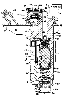
Figure 1 is a side section view of a float vent valve
incorporating the present invention, mounted in the fuel
tank and connected to a carbon canister;
Figure 2 is an exploded assembly view of the main
components of the valve of Figure 1;
Figure 3 is a sectional plan view of the anti-splash
baffle structure in the valve embodiment of Figure 1.
Figures 4 is a detail side view of the pressure relief
valve lips in the valve of Figure 1.
CA 02268112 1999-04-08
WO 98I15761 PCT/IJS97/18142
-4-
Best Mode For Carrying Our the Invention
Referring first to Figure 1, an automotive fuel tank
is shown with a standard filler pipe 12 and a carbon
canister type vapor collecting apparatus 14 for processing
excess fuel vapor released from the tank. A float-type
vent valve 20 incorporating the present invention is shown
mounted to the tank in typical fashion, i.e. mounted to the
top wall 11 of the tank through a suitable aperture sized
to receive the valve. Vent valve 20 extends at least
partially into the interior of the tank to a point designed
to be submerged by relatively high fuel levels in the tank.
Vent valve 20 selectively opens and closes a venting
pathway 13 from the tank to canister 14 in response to fuel
level. For example, as liquid fuel level rises toward a
full level during refueling, liquid fuel rising over vent
valve 20 will progressively force an internal float valve
mechanism 22 upwardly to a closed position, shutting off
the flow of fuel vapor from the tank through valve 20 to
canister 14 via pathway 13.
Vent valve 20 includes a float valve mechanism 22
comprising a float 22a, a spring 22b, a valve assembly 22c
on the upper end of the float, a vent outlet 22d
communicating with vent line 13 to the canister, and a
valve seat 22e which is engaged in sealing fashion by the
valve assembly 22c to close the valve in response to rising
fuel level.
Float valve mechanism 22 can be mass-balanced in known
manner as desired for preferred action in liquid fuel.
CA 02268112 1999-04-08
WO 98/15761 PCT/US97/18142 -
-5-
Some known options include a lighter than fuel float, a
float of neutral buoyancy in fuel, and a heavier than fuel
float. Spring 22b is provided to cooperate with the
desired float density to achieve an appropriate
responsiveness for proper opening and closing under various
operating conditions. The variations in mass balancing the
float/spring combination for different applications are
well known to those skilled in the art, and are not in
themselves part of the present invention.
Adjusting the responsiveness of the float also adjusts
the effective "full" fuel level in the tank if vent valve
20 is used as a fill control valve. For example,
increasing spring force on the float effectively lightens
the float, making it more responsive to fuel level and
lowering the "full" level at which the float closes and
reducing the total fuel capacity of the tank.
The valve assembly 22c on the upper end of the float
may take any known form; the illustrated embodiment of
valve assembly 22c is one of many valve closing mechanisms
which can be applied to the float. The variety of suitable
valve structures will be apparent to those skilled in the
art.
Although the float spring combination in vent valve 20
can be designed for general buoyancy characteristics or
responsiveness in liquid fuel, the combination must be
fine-tuned or calibrated for precise operation. The
present invention provides for just such calibration in a
simple and economical manner.
CA 02268112 1999-04-08
WO 98I15761 PCT/US97/18142 '
-6-
In order to carry out the present invention, vent
valve 20 is provided at its lower end with a float
calibration mechanism 24 comprising a calibration plate
24a. The illustrated calibration plate 24a includes an
upper spring seat 24b, a push-to-calibrate lower surface
24c, a force probe aperture 24d, and a portion or surface
24e which can be fastened to the valve body in permanent or
semi-permanent manner once the calibration is complete, for
example by spot welding to the~valve body.
Referring now to Figures 1 and 3-4, the operation of
the float calibration mechanism 24 will be described.
Calibration plate 24a is axially adjustable within the
lower portion 20b of the vent valve, sliding smoothly up
and down in calibration chamber 20c. The fit between the
outer surface 24e of calibration plate 24a and the inner
surface of the lower valve body chamber housing the
calibration plate is preferably toleranced for a sliding
friction fit such that calibration plate 24a remains in
position, even against the force of spring 22b, when it is
released.
Although the term "plate" is used with reference to
calibration plate 24a, it will be understood from the
drawing that it need not literally be plate-shaped. In the
illustrated embodiment calibration plate 24a takes the
preferred form of a cylindrical symmetrical spool, but
other shapes are possible provided they provide a seat or
support for the spring and a push/pull-to-calibrate
function.
CA 02268112 1999-04-08
WO 98/15761 PCT/US97/18142
The preferred method for calibrating the float
mechanism 22 is to measure the grams of force which the
weight of the float 22a (balanced by spring 22b) exerts
just prior to valve closure, i.e, when seal member 22f of
valve assembly 22c is about to engage valve seat 22e. This
is typically a small distance, for example on the order of
.015 to .020 inches, although this is variable depending on
the functional requirements of the particular valve. In
the present invention this force is measured by inserting
a force probe of known type, for example a strain gauge
type probe, through aperture 24d in calibration plate 24a
against the bottom of float 22a at 22g, and pushing the
float upwardly until it is at the desired point, here just
prior to closure. By measuring the force exerted against
the probe by the spring-balanced float 22a, it can be
determined by one skilled in the art whether the upward
spring force on the float needs to be higher or lower. If
lower, then calibration plate 24a is adjusted downwardly in
chamber 20c, effectively reducing the force of the spring
on the float just prior to closure. If the upward spring
force just prior to closing needs to be increased, then the
calibration plate 24a is moved upwardly in chamber 20c
unt-il the proper force balance is achieved. In this
respect aperture 24d plays a dual role, not only providing
an entry for the force probe, but further providing a
purchase for pulling plate 24a down.
CA 02268112 1999-04-08
WO 98I15761 PCT/US97/18142 -
_g_
Industrial A~plicabilitv
In use the mechanism of the present invention has
been found to achieve accuracies within plus or minus .10
grams at a specified distance and load for calibration.
It will be appreciated by those skilled in the art that
the calibration plate can be adjusted up or down as
desired until the float valve is calibrated as close as
possible to the desired force at specified distance and
load.
Once the valve has been calibrated as described
above, the calibration plate is then fixed in place, for
example in the illustrated embodiment by spot welding a
portion 24e of the outer surface of the plate to the
inner surface of chamber 20c. However, it will be
apparent to those skilled in the art that various known
techniques may be used to fix calibration plate 24a in
place, including different welding techniques, adhesives,
or even mechanical means such as but not limited to pins
or snap-detents.
It will be appreciated that the calibration plate is
preferably centered with respect to the longitudinal axis
of the float mechanism 22, in order to provide accurate
force measurements via the in-line force probe aperture
24d.
The present invention is illustrated in a float-type
vent valve incorporating additional features of an
inventive nature. Referring to Figures 1 and 3, the
presently illustrated vent valve includes an anti-splash
CA 02268112 1999-04-08
WO 98/15761 PCT/US97I18142 '
-9-
baffle structure 26 designed to limit the entry of liquid
fuel through radial ports 26a in the float valve body
which would tend to splash up through vent outlet 22d
before the float mechanism 22 has closed. One or more
radial ports 26a are needed to provide adequate vapor
venting through the valve when the fuel level lies below
them. However, sloshing and splashing of the fuel in the
tank can create surges which break over and through
ports) 26a, threatening to splash liquid fuel through
vent outlet 22d and into the carbon canister. This is
undesirable, because the carbon canister is designed to
handle vapor rather than liquid fuel, and quickly becomes
saturated and its function thereby impaired.
In the illustrated embodiment, baffle structure 26
includes a baffle plate 26b having a width (or
circumferential length) approximately equal to or~greater
than the width (or circumferential length) of window 26a.
While only a single window 26a with a single
corresponding baffle 26b is illustrated, it will be
apparent to those skilled in the art that multiple
baffles 26b can be provided to protect multiple windows.
In the illustrated embodiment, baffle 26b is formed
as an integral, downwardly-depending portion of a unique
baffle plate structure 26c (Figure 2) which also defines
vent outlet 22d and valve seat 22e at an upper end of the
float chamber 22h. It is not necessary for baffle 26b to
be formed as an integral part of baffle plate structure
26c as illustrated, although this is a presently
CA 02268112 1999-04-08
WO 98/15761 PCT/US97/18142 -
-IO-
preferred form. Baffle plate 26b may be fastened or
positioned within the valve body in any known manner to
protect splash-through from radial ports 26a.
Also disclosed in the illustrated vent valve
embodiment is a novel pressure relief assembly 28 located
at the upper end of the valve, comprising a housing 28a,
cover 28b, a relief spring 28c, a relief seal member 28d
with sealing lips 28e, a vent orifice 28f, a weld joint
28g, and a steel stamping 28h which provides seal
protection and spring retainer functions. Referring to
Figures 1 and 4, the pressure relief assembly operates to
selectively open and close venting through a pressure
relief port 28i formed in the side of the upper portion
20a of vent valve 20. Release spring 28c maintains
relief seal member 28d in the closed-position shown in
Figure 1, with sealing lips 28e held firmly against valve
seat 28j to block the flow of vapor from the fuel tank
through pressure relief port 28i to a suitable relief
point (not shown), such as the atmosphere or the carbon
canister. When vapor pressure in the fuel tank rises
above a predetermined safety level, the vapor pressure
will overcome the force of relief spring 28c to force
seal member 28d off its valve seat and open relief
venting through port 28i to the relief point.
Pressure relief assembly 28 includes a number of
individually novel features. Seal member 28d exhibits
sealing lips 28e having a reverse, inwardly-facing
contour which provides an unusually supple (therefore
CA 02268112 1999-04-08
WO 98I15761 PCT/US97/18142
-11-
secure) sealing surface with the valve seat 28j, and
further allows pressure P from the fuel tank to aid the
spring in the sealing action as shown in Figure 4.
Pressure from the fuel tank, illustrated at arrow P,
engages the interior surface of reverse lips 28e to
assist in forcing the lips into sealing engagement with
the valve seat. In this manner vapor pressure from the
tank aids sealing until the lips finally leave the
seating surface.
Another feature of pressure relief assembly 28 is
the secondary spring retainer 28h, in the illustrated
embodiment a resilient steel stamping preferably having a
non-vaportight engagement with housing 28a, or optionally
having a small pressure relief port illustrated at 28j.
Spring retainer 28h is preferably a resilient metal, with
an outer lip portion 28k which engages or "bites " into
the plastic material of the pressure relief housing 28a
when inserted to stay in place. This allows a simple
press-mounting of the spring into housing 28a via the
retainer before the cover 28b is welded into place. The
optional pressure relief port 28j in spring retainer 28h
is relatively small, for example on the order of .010
inches in diameter. The non-vaportight fit between the
retainer 28h and housing 28a, and/or the optional
pressure relief port 28j, prevents pressure buildup
between retainer 28h and cover 28b when the cover is
welded in place. Retainer 28h with its tight press-fit
into the bore of housing 28a additionally prevents weld
CA 02268112 1999-04-08
WO 98/15761 PCT/US97/18142 -
-12-
flash and dust from falling into or contaminating the
resilient rubber pressure relief seal 28d.
It will be apparent to those skilled in the art that
the foregoing description of an illustrated embodiment is
exemplary in nature, and can be modified for various vent
valve applications without departing from the scope of
the invention defined by the following claims.
We claim: