Language selection

Search

Patent 2268148 Summary

Third-party information liability

Some of the information on this Web page has been provided by external sources. The Government of Canada is not responsible for the accuracy, reliability or currency of the information supplied by external sources. Users wishing to rely upon this information should consult directly with the source of the information. Content provided by external sources is not subject to official languages, privacy and accessibility requirements.

Claims and Abstract availability

Any discrepancies in the text and image of the Claims and Abstract are due to differing posting times. Text of the Claims and Abstract are posted:

  • At the time the application is open to public inspection;
  • At the time of issue of the patent (grant).
(12) Patent Application: (11) CA 2268148
(54) English Title: WINCH DRIVE
(54) French Title: DISPOSITIF D'ENTRAINEMENT POUR WINCH
Status: Deemed Abandoned and Beyond the Period of Reinstatement - Pending Response to Notice of Disregarded Communication
Bibliographic Data
(51) International Patent Classification (IPC):
  • B66D 01/74 (2006.01)
  • B66D 01/12 (2006.01)
(72) Inventors :
  • STROM, WILLIAM (Switzerland)
(73) Owners :
  • WILLIAM STROM
(71) Applicants :
  • WILLIAM STROM (Switzerland)
(74) Agent: MARKS & CLERK
(74) Associate agent:
(45) Issued:
(86) PCT Filing Date: 1997-10-07
(87) Open to Public Inspection: 1998-04-16
Examination requested: 2002-10-04
Availability of licence: N/A
Dedicated to the Public: N/A
(25) Language of filing: English

Patent Cooperation Treaty (PCT): Yes
(86) PCT Filing Number: PCT/GB1997/002737
(87) International Publication Number: GB1997002737
(85) National Entry: 1999-04-07

(30) Application Priority Data:
Application No. Country/Territory Date
9620883.0 (United Kingdom) 1996-10-07

Abstracts

English Abstract


A winch drive comprising a portable power tool having a bit (4) shaped to fit
the drive socket (11) at the top of a winch (12). The power tool includes a
self-tailing device (14) and is preferably battery driven.


French Abstract

Dispositif d'entraînement pour winch formée d'un outil de puissance possédant un élément de connexion (4) formé pour s'insérer dans la prise d'entraînement (11) qui se trouve au sommet d'un winch (12). L'outil de puissance comporte de préférence un dispositif d'enroulement automatique (14) et est actionné de préférence par batterie.

Claims

Note: Claims are shown in the official language in which they were submitted.

5
Claims:
1) A winch drive comprising a portable power tool having a bit shaped to fit
the
drive socket at the top of a winch and including a self-tailing device.
2) A winch drive as claimed in Claim 1, wherein the self-tailing device
comprises
two annular discs movable apart against a resilient bias to hold a line passed
therebetween.
3) A winch drive as claimed in Claim 1 or 2, wherein the self-tailing device
includes a line guide for guiding the line between the discs.
4) A winch drive as claimed in any one of the preceding claims, wherein the
shaped bit is integral with the power tool.
5) A winch drive as claimed in any one of the preceding claims, wherein the
power
tool is battery driven.
6) A winch drive as claimed in Claim 5, wherein the power tool has battery
recharging means.
7) A winch drive as claimed in Claim 5 or 6, wherein the power tool has a
detachable battery housing.
8) A winch drive as claimed in any one of the preceding claims, wherein the
power
tool has a handle extending substantially radially to the axis of the shaped
bit for
holding the tool during driving.
9) A winch drive as claimed in Claim 8, wherein the handle is detachable.

6
10) A winch drive as claimed in Claims 7 and 9, wherein the handle constitutes
the
battery housing.
11) A winch drive as claimed in any one of the preceding claims, wherein the
power
tool has means for reversing the direction of drive of the shaped bit thereby,
in use,
changing the speed of winching.
.
12) A winch drive as claimed in any one of the preceding claims, wherein the
power
tool has a torque and/or speed control.
13) A winch drive substantially as herein described with reference to any one
of the
embodiments shown in the accompanying drawings.
14) A method of driving a winch using a winch drive as claimed in any one of
the
preceding claims.

Description

Note: Descriptions are shown in the official language in which they were submitted.


CA 02268148 1999-04-07
WO 98I15488 PCT/G897/02737
Winch Drive
The present invention relates to a winch drive, particularly for a boat or
yacht.
Winches are commonly used on yachts or other boats for tensioning or pulling
running
rigg, usually a line wound around the drum of the winch. The winch is normally
rotated manually, and a standard shaped socket is provided in the top of the
winch into
which the correspondingly shaped end of a handle is inserted. Rotation of the
handle
rotates the winch and tensions the line. Manually rotating the winch can be
difficult
work, particularly under certain conditions, eg with heavy load and/or in bad
weather.
It is known to power some forms of winch by means of an electric motor
situated below
deck immediately under the winch. Such a motor takes up valuable under-deck
space,
and can be difficult to access for servicing.
An object of this invention is to provide a winch drive, which is simple to
operate and
does not occupy under-deck space.
The invention provides a winch drive as claimed in Claim 1.
Although the shaped bit may be retractable, it is preferably integral with the
power tool.
Preferably, the power tool is battery driven, and the batteries are
rechargeable. The
batteries may be accommodated within a handle of the power tool or in a
separate
detachable battery housing.
Embodiments of the invention will now be described with reference to the
accompanying drawings, wherein:
SU~ST1TUTE SHEET (RULE ~6)

n n I
CA 02268148 1999-04-07
WO 98I15488 PCT/GB97/02737
2
Fig. 1 is a perspective view of a first embodiment of a winch drive in
accordance with
the invention but not showing the self-tailing device,
Fig. 2 is a perspective view of a second embodiment of a winch drive in
accordance
with the invention but not showing the self tailing device,
Fig. 3 is a plan view of a winch showing the standard socket for engagement by
the
shaped end of a winch handle,
Figs. 4A, B and C are underside views of shaped bits for the power drives of
Figs. 1
and 2, and
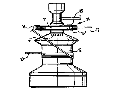
Fig. ~ is a side view of the winch drive of Fig. 1 and showing the self
tailing device.
In Fig. I a winch power drive comprises a body 1 housing an electric motor 2
drivingly
connected via a shaft 3 to a shaped bit 4.
The body I also houses one or more batteries S, which are preferably
rechargeable via a
connection b. The portion 7 of the body 1 housing the battery 5 may be
detachable for
ease of recharging. The body 1 may be provided with finger-shaped recesses 1
'to
facilitate gripping by the operator.
The winch drive has a handle 8, which may be detachable, to prevent rotation
of the
body 1 while the shaped bit 4 is driven by the electric motor 2.
The body i also has a forward and reverse switch 9 as well as a high/low speed
control
button 10.
The self tailing device is described with reference to Fig. 5.

CA 02268148 1999-04-07
WO 98I15488 PCTIGB97/02737
3
The winch drive in Fig. 2 is similar to that shown in Fig. I , but has a
different shape.
The battery or batteries 5 are contained either in a detachable battery
housing 7 or in the
handle 8.
The bit 4 of the winch drive is shaped to engage the standard socket at the
top of a
winch 12, as shown in Fig. 3. The bit 4 may have the shape as shown in Figs.
4A, 4B
or 4C to fit snugly into the socket 11.
In accordance with the invention, and as shown in Fig. 5, the winch drive has
a self
tailing device 14. This comprises two spaced, annular-shaped discs I5, 15',
one of
which (here 151) is resiliently movable away from the other disc against the
bias of a
spring (not shown). The self tailing device 14 also has a line guide 16.
In use the winch drive is placed on top of the winch so that the bit 4 engages
the socket
11 as shown in Fig. 5. The line 13 is wound around the winch 12 and the end 17
of the
line is wound around the line guide 16 and drawn between the discs 15, 15 '
against the
bias of the spring (not shown). Thus, the end 17 of the line 13 is firmly held
by the
self-tailing device 14 to free both hands for operation of the winch drive.
The operator holds the body 1 of the winch drive and the handle securely and
switches
on the electric motor to drive the winch to tension the rope 13 to the
required degree
The winch can be driven at different speeds by operation of the speed control
button 10,
and also by operation of the forward and reverse switch 9. The standard
construction of
a boat winch 12 is such that when the socket 11 is rotated in one direction
the winch
rotates at one speed, whereas when the socket is rotated in the opposite
direction the
winch rotates in the same direction as previously, but at a different speed.
When the line is to be released, the end 17 is merely pulled out from between
the discs
1 S,151 and unwound from the winch 12.

11
CA 02268148 1999-04-07
WO 98115A88 PCTIGB97I02737
4
The self tailing device need not be as shown in Fig. 5 but may be adapted from
any
standard self tailing device normally applied to winches.
Although the winch drive shown in the drawings is battery driven, it could,
for
example, be driven by a wind-up clockwork motor directly, or by a clockwork
motor
via an electric generator.

Representative Drawing
A single figure which represents the drawing illustrating the invention.
Administrative Status

2024-08-01:As part of the Next Generation Patents (NGP) transition, the Canadian Patents Database (CPD) now contains a more detailed Event History, which replicates the Event Log of our new back-office solution.

Please note that "Inactive:" events refers to events no longer in use in our new back-office solution.

For a clearer understanding of the status of the application/patent presented on this page, the site Disclaimer , as well as the definitions for Patent , Event History , Maintenance Fee  and Payment History  should be consulted.

Event History

Description Date
Inactive: IPC from MCD 2006-03-12
Time Limit for Reversal Expired 2005-10-07
Application Not Reinstated by Deadline 2005-10-07
Deemed Abandoned - Failure to Respond to Maintenance Fee Notice 2004-10-07
Letter Sent 2002-11-05
Request for Examination Received 2002-10-04
Request for Examination Requirements Determined Compliant 2002-10-04
All Requirements for Examination Determined Compliant 2002-10-04
Letter Sent 2001-12-10
Inactive: Entity size changed 2001-12-10
Inactive: Office letter 2001-11-20
Reinstatement Requirements Deemed Compliant for All Abandonment Reasons 2001-10-30
Deemed Abandoned - Failure to Respond to Maintenance Fee Notice 2001-10-09
Inactive: Cover page published 1999-06-02
Inactive: Notice - National entry - No RFE 1999-05-13
Inactive: First IPC assigned 1999-05-12
Application Received - PCT 1999-05-07
Application Published (Open to Public Inspection) 1998-04-16

Abandonment History

Abandonment Date Reason Reinstatement Date
2004-10-07
2001-10-09

Maintenance Fee

The last payment was received on 2003-10-07

Note : If the full payment has not been received on or before the date indicated, a further fee may be required which may be one of the following

  • the reinstatement fee;
  • the late payment fee; or
  • additional fee to reverse deemed expiry.

Patent fees are adjusted on the 1st of January every year. The amounts above are the current amounts if received by December 31 of the current year.
Please refer to the CIPO Patent Fees web page to see all current fee amounts.

Fee History

Fee Type Anniversary Year Due Date Paid Date
MF (application, 2nd anniv.) - small 02 1999-10-07 1999-04-07
Basic national fee - small 1999-04-07
MF (application, 3rd anniv.) - small 03 2000-10-10 2000-10-10
Reinstatement 2001-10-30
MF (application, 4th anniv.) - standard 04 2001-10-09 2001-10-30
Request for examination - standard 2002-10-04
MF (application, 5th anniv.) - standard 05 2002-10-07 2002-10-07
MF (application, 6th anniv.) - standard 06 2003-10-07 2003-10-07
Owners on Record

Note: Records showing the ownership history in alphabetical order.

Current Owners on Record
WILLIAM STROM
Past Owners on Record
None
Past Owners that do not appear in the "Owners on Record" listing will appear in other documentation within the application.
Documents

To view selected files, please enter reCAPTCHA code :


To view images, click a link in the Document Description column. To download the documents, select one or more checkboxes in the first column and then click the "Download Selected in PDF format (Zip Archive)" or the "Download Selected as Single PDF" button.

List of published and non-published patent-specific documents on the CPD .

If you have any difficulty accessing content, you can call the Client Service Centre at 1-866-997-1936 or send them an e-mail at CIPO Client Service Centre.


Document
Description 
Date
(yyyy-mm-dd) 
Number of pages   Size of Image (KB) 
Representative drawing 1999-06-01 1 10
Abstract 1999-04-06 1 49
Description 1999-04-06 4 119
Claims 1999-04-06 2 45
Drawings 1999-04-06 2 40
Notice of National Entry 1999-05-12 1 194
Courtesy - Abandonment Letter (Maintenance Fee) 2001-11-05 1 183
Notice of Reinstatement 2001-12-09 1 171
Reminder - Request for Examination 2002-06-09 1 118
Acknowledgement of Request for Examination 2002-11-04 1 176
Courtesy - Abandonment Letter (Maintenance Fee) 2004-12-01 1 176
PCT 1999-04-06 9 313
Fees 2002-10-06 1 39