Language selection

Search

Patent 2268202 Summary

Third-party information liability

Some of the information on this Web page has been provided by external sources. The Government of Canada is not responsible for the accuracy, reliability or currency of the information supplied by external sources. Users wishing to rely upon this information should consult directly with the source of the information. Content provided by external sources is not subject to official languages, privacy and accessibility requirements.

Claims and Abstract availability

Any discrepancies in the text and image of the Claims and Abstract are due to differing posting times. Text of the Claims and Abstract are posted:

  • At the time the application is open to public inspection;
  • At the time of issue of the patent (grant).
(12) Patent Application: (11) CA 2268202
(54) English Title: MILLER CUTTERHEAD WITH TWO CONTINUOUS ROTATIONS AND DIRECT DRIVE
(54) French Title: TETE DE COUPE DE FRAISEUSE A DEUX ELEMENTS DE ROTATION CONTINUE ET A ENTRAINEMENT DIRECT
Status: Deemed Abandoned and Beyond the Period of Reinstatement - Pending Response to Notice of Disregarded Communication
Bibliographic Data
(51) International Patent Classification (IPC):
  • B23C 05/00 (2006.01)
  • B23Q 01/54 (2006.01)
  • B23Q 05/10 (2006.01)
(72) Inventors :
  • SAEZ MARTINEZ, JOSE IGNACIO (Spain)
(73) Owners :
  • INDUSTRIAS ANAYAK, S.A.
(71) Applicants :
  • INDUSTRIAS ANAYAK, S.A. (Spain)
(74) Agent: SWABEY OGILVY RENAULT
(74) Associate agent:
(45) Issued:
(22) Filed Date: 1999-04-07
(41) Open to Public Inspection: 2000-10-07
Availability of licence: N/A
Dedicated to the Public: N/A
(25) Language of filing: English

Patent Cooperation Treaty (PCT): No

(30) Application Priority Data: None

Abstracts

English Abstract


Miller cutterhead with two continuous rotations and direct drive, of the kind
that is comprised of slide, cutterhead and main spindle, where: a)-. the
cutterhead is a modular element and has a first and second supplementary
rotation spindle, to convert a three-spindle grinding centre or milling
machine into a five spindle one; b)-. it has a first motor coupled directly
onto the first supplementary rotation spindle with the stator fixed on the
slide and with its motor fixed on the cutterhead; and c)-. it has a second
motor coupled directly onto the second rotation spindle. The first and second
motors are high torque flat motors with a low speed range; in particular
direct servomotors, without any intermediate transmission or reduction.
Application in machine-tool.


Claims

Note: Claims are shown in the official language in which they were submitted.

5
CLAIMS
1.- Miller cutterhead with two continuous rotations and direct
drive, comprised of a slide, cutterhead and main spindle, characterised
because
the cutterhead is a modular element and has a first and second supplementary
rotation spindle, to convert a three-spindle grinding centre or milling
machine
into a five-spindle one; because it has a first motor coupled directly onto
the
first supplementary rotation spindle with its stator fixed on the slide and
with
its rotor fixed on the cutterhead; and because it has a second motor coupled
directly onto the second rotation spindle.
2.- Miller cutterhead with two continuous rotations and direct
drive, according to above claim, characterised because the first and second
motors are high torque flat motors with a low speed range; in particular
direct
servomotors, without any intermediate transmission or reduction.

Description

Note: Descriptions are shown in the official language in which they were submitted.


CA 02268202 1999-04-07
"MILLER CUTTERHEAD WITH TWO CONTINUOUS
ROTATIONS AND DIRECT DRIVE".
The object of this invention is a cutterhead that provides the
tool with two continuous additional rotations in order to convert a three-
spindle grinding centre or milling machine into a five-spindle one. With this
solution a traditional vertical milling machine can be transformed into a five-
spindle one, all of them in the tool.
Of the two additional rotations that the cutterhead of the
invention provides, one of them is parallel to the table and the other
perpendicular to the table.
Traditionally, these rotations of the tool have been generated
by motors, located on the upper part of the ram, accompanied by some
transmissions that provide the rotation at the tip of the tool.
The solution adopted by this cutterhead is to use high torque
direct motors with relatively low speed ranges, which permits the location or
coupling of the motors directly on the rotation spindle, providing a more
compact solution.
This cutterhead is a modular element that can be considered as
an accessory for the machine.
In this invention high torque flat motors have been used with
low speed ranges; in particular direct servomotors, without any intermediate
transmission or reduction, which produce rotary movements, providing the
assembly with a good control and high dynamics.
The advantages or dynamic features achieved with the
invention both in accelerations and limit speeds represent an increase of up
to
100% respect to the currently known cutterheads.
This invention advocates a miller cutterhead with two
rotations and direct drive, comprised of a slide, cutterhead and main spindle,
and it is characterised because the cutterhead is a modular element and has a

CA 02268202 1999-04-07
2
first and second supplementary rotation spindle, to make a three-spindle
grinding centre or milling machine into a five-spindle one; because it has a
first motor coupled directly on the first supplementary rotation spindle with
its
stator fixed in the slide and with its rotor fixed in the cutterhead; and
because
it has a second motor coupled directly in the second rotation spindle.
It is also characterised because the first and second motors are
high torque flat motors with a low speed range; in particular direct
servomotors, without any intermediate transmission or reduction.
This cutterhead is designed to be applied in medium-sized or
large grinding centres and milling machines, where it is necessary to work
with five spindles. These machines must include numerical controls with high
features and with capacity to interpolate five spindles at the same time.
It will preferably be applied on vertical grinding centres, but it
can be implanted additionally on horizontal centres.
The advantages provided by the proposed solution of the
miller cutterhead with two continuous rotations and direct drive, targeted by
this invention are:
. Simplification of the design on eliminating mechanical
transmissions.
. More compact solution, minimising volume and weight.
. Great rigidity of the cutterhead opposed to traditional
solution.
. Greater reliability inherent to the reduction of the number of
components.
. Elimination of the transmission chains
. Elimination of the mechanical hysteresis.
. High angular acceleration because this corresponds directly
with that of the motor.
. Reduction of the inertia.

CA 02268202 1999-04-07
3
To reach a better understanding of the object of this invention,
a preferential form of practical execution is represented on the drawings,
susceptible to accessory changes that will not change the basic design.
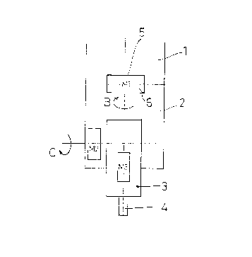
Figure 1 is a schematic representation of a practical execution
of the cutterhead targeted by this invention.
Below an example of a practical execution of this invention is
described, but it is not limiting.
In figure 1 the slide (1), cutterhead (2) and main spindle (3)
have been represented in a coaxial mode.
Milling machines with a slide ( 1 ) equipped with movement on
three spindles and a cutterhead (2) with movement on another two
supplementary spindles (B) (C) are already known.
For the movement of the supplementary spindle (B)
traditionally there is a first motor (M'2) (not represented) placed on the
slide
( 1 ) and a second motor (M'2) (not represented) placed on the cutterhead (2),
requiring a transmission complex between them both and the relative rotation
spindles for the tool (4) to achieve the desired movements.
Figure 1 shows that, in accordance with the invention, the first
motor (Ml) to achieve the supplementary rotation (B) has its stator (5) fixed
to
the slide (1) and the rotor (6) fixed to the cutterhead (2) and on the spindle
(B)
of the supplementary rotation.
The second motor (M2) is placed on the cutterhead (2) in a
coaxial fashion and on the spindle itself ( C) of the supplementary rotation
to
be achieved.
It can be seen that with this arrangement the transmissions
disappear so the dynamic features of the machine are substantially improved.
The first and second motors (M 1 ), (M2) are high torque flat
motors with a low speed range which, as already mentioned, are coupled

CA 02268202 1999-04-07
4
directly onto the relative rotation spindle (B), (C) providing a more compact
solution.
In particular, the first and second motors (M1), (M2) are
direct servomotors and the speed ranges used are relatively low, up to 120
r.p.m.
Of the two supplementary rotations or spindles (B) ( C), one
of them is parallel to the work table (not represented) and the other is
perpendicular to it. As a result, the servomotors (M 1 ), (M2) are located
coaxially and radially with the electric boring bar.
It has also been arranged for the main motor (M3) or electric
boring bar to be placed coaxially to the main spindle (3).

Representative Drawing
A single figure which represents the drawing illustrating the invention.
Administrative Status

2024-08-01:As part of the Next Generation Patents (NGP) transition, the Canadian Patents Database (CPD) now contains a more detailed Event History, which replicates the Event Log of our new back-office solution.

Please note that "Inactive:" events refers to events no longer in use in our new back-office solution.

For a clearer understanding of the status of the application/patent presented on this page, the site Disclaimer , as well as the definitions for Patent , Event History , Maintenance Fee  and Payment History  should be consulted.

Event History

Description Date
Inactive: IPC from MCD 2006-03-12
Application Not Reinstated by Deadline 2002-04-08
Time Limit for Reversal Expired 2002-04-08
Deemed Abandoned - Failure to Respond to Maintenance Fee Notice 2001-04-09
Application Published (Open to Public Inspection) 2000-10-07
Inactive: Cover page published 2000-10-06
Inactive: First IPC assigned 1999-05-26
Letter Sent 1999-05-11
Inactive: Filing certificate - No RFE (English) 1999-05-11
Application Received - Regular National 1999-05-07

Abandonment History

Abandonment Date Reason Reinstatement Date
2001-04-09

Fee History

Fee Type Anniversary Year Due Date Paid Date
Registration of a document 1999-04-07
Application fee - standard 1999-04-07
Owners on Record

Note: Records showing the ownership history in alphabetical order.

Current Owners on Record
INDUSTRIAS ANAYAK, S.A.
Past Owners on Record
JOSE IGNACIO SAEZ MARTINEZ
Past Owners that do not appear in the "Owners on Record" listing will appear in other documentation within the application.
Documents

To view selected files, please enter reCAPTCHA code :


To view images, click a link in the Document Description column (Temporarily unavailable). To download the documents, select one or more checkboxes in the first column and then click the "Download Selected in PDF format (Zip Archive)" or the "Download Selected as Single PDF" button.

List of published and non-published patent-specific documents on the CPD .

If you have any difficulty accessing content, you can call the Client Service Centre at 1-866-997-1936 or send them an e-mail at CIPO Client Service Centre.

({010=All Documents, 020=As Filed, 030=As Open to Public Inspection, 040=At Issuance, 050=Examination, 060=Incoming Correspondence, 070=Miscellaneous, 080=Outgoing Correspondence, 090=Payment})


Document
Description 
Date
(yyyy-mm-dd) 
Number of pages   Size of Image (KB) 
Representative drawing 2000-10-01 1 4
Abstract 1999-04-06 1 21
Drawings 1999-04-06 1 6
Description 1999-04-06 4 146
Claims 1999-04-06 1 23
Courtesy - Certificate of registration (related document(s)) 1999-05-10 1 116
Filing Certificate (English) 1999-05-10 1 165
Reminder of maintenance fee due 2000-12-10 1 112
Courtesy - Abandonment Letter (Maintenance Fee) 2001-05-06 1 182