Note: Descriptions are shown in the official language in which they were submitted.
CA 02268410 1999-04-09
WO 98/16699 PCT/AU97/00681
-1-
BUILDING ELEMENTS
TECHNICAL FIELD
This invention relates to the construction industry; more
particularly, this invention relates to certain building
elements useful in construction, especially for the building of
internal walls and partitions, although the invention is not
necessary limited to this application.
BACKGROUND ART
For many years it has been the normal practice in the
construction industry to construct internal walls from
plasterboard, attached to wooden or metal studs. To install
plasterboard walls with an acceptably smooth finish, and to
set the joints between adjacent plasterboard panels, it is
necessary to employ skilled plasterboard "setters". This not
only increases costs, but influences the building timetable; to
achieve maximum efficiency, a building should be prepared to
the stage where all plasterboard walls can be installed at one
time, so that the setters are on site for the minimum time
necessary. A significant cost drawback is the fact that it is
unavoidable that this work must be carried out on site.
Once the plasterboard walls have been installed, they need to
be sanded before being painted. The sanding procedure creates
a significant amount of gypsum dust, with a consequent effect
on all articles and material on the site. Moreover, because it
is necessary to paint plasterboard, the cost of painting is a
significant part of building.
Should it become necessary to repair a plasterboard wall, if a
professional finish is required, it is necessary to call in a
plasterboard setter and to endure the dust created during the
sanding procedure. In addition, it is necessary to repaint the
wall after repair.
= CA 02268410 1999-04-09
WO 98/16699 PCT/AU97/00681
There is a further problem associated with plasterboard walls,
which arises during demolition. Demolition of internal
plasterboard walls is frequently necessary in commercial
buildings, for example, when a tenant leaves the building.
Demolition of plasterboard walls is usually also necessary
during refurbishment. Plasterboard walls cannot be dismantled
without substantial damage to the plasterboard, to the extent
that the plasterboard is not reusable. Even more
significantly, substantial gypsum dust is created. It is
believed that the inhalation of gypsum dust may have a
deleterious effect on health. Consequently, in some
jurisdictions, safe work practices require that adjacent areas
are evacuated during the demolition of plasterboard walls. This
can result in loss of rent for a landlord and interruption of
business and loss of profits for a tenant.
After plasterboard walls have been demolished, the plasterboard
has a"negative" value in that it is necessary to pay for its
removal and disposal. Plasterboard and its framing is not
recyclable on an economic basis. It is an aim of the present
invention to provide a construction system which can avoid the
use of plasterboard panels and hence the difficulty and cost
involved in construction, repair and demolition involving
plasterboard panels.
It is a further object of this invention to provide a building
system which can permit wall panels to be reusable.
It is a further object to provide, in one aspect of the
invention, a system which can use wall panels already finished
in the factory, so that painting on site is not required.
When wall panels, plasterboard or otherwise, are transported to
a building site, damage frequently occurs. In many cases, the
damage is relatively minor, and one side of the panel is
usable.
It is an object of this invention, in one aspect, to provide a
building element which will permit a panel to be erected with
SUBSTITUTE SHEET (RULE 26)
CA 02268410 2008-01-18
- 3 -
either side outermost.
During occupation of buildings, damage is occasionally
caused to wall panels. Rather than obtain a replacement
panel, it would be desirable to be able to detach the panel
and reverse it so that the damaged side is concealed in the
wall cavity. This invention, in one aspect, aims to
provide that capability.
It is yet a further object of this invention to provide a
building system which can be integrated with furniture,
especially office furniture, such as work stations.
DISCLOSURE OF THE INVENTION
Accordingly, this invention provides a stud comprising a
first set of channels parallel to and spaced from a second
set of channels by spacing means, wherein:
each channel in each of the first set of channels
and the second set of channels is adapted to receive
a cooperating means for the purpose of mounting a
panel or bracket on the stud, and the first set of
channels includes a first base and the second set of
channels includes a second base;
each of the first set of channels is defined by the
first base and a pair of side walls and each of the
second set of channels is defined by the second base
and a pair of side walls; and
each pair of adjacent channels in each of the first
set of channels and the second set of channels share
a side wall.
CA 02268410 2008-01-18
-3a-
According to another aspect of the present invention, there
is provided a stud comprising:
a first set of three or more channels and a second
set of three or more channels, each channel in each
set being adapted to receive a cooperating means for
mounting a panel or a bracket on the stud, the first
set of channels being parallel to and spaced from
the second set of channels by spacing means, wherein
the spacing means provides a direct connection
between the first set of channels and the second set
of channels, the spacing means being located inboard
of an outer two channels of each set, and wherein
each channel is formed by a base and side walls, the
bases of the channels being aligned, and an opening
for each channel is located between the side walls,
the openings of the channels of the first set facing
outwardly in an opposite direction to the openings
of the channels of the second set.
The cross-sectional shape of each channel can be determined
by the way in which it is intended to receive the
cooperating means. In one preferred embodiment, rather
than being "U" shaped, it is preferred that each channel is
formed with return rims, so that the channel is "C" shaped
in cross-section; however, it is greatly preferred that the
base of the channel is flat..
The stud may be manufactured from any suitable material; it
has been found that aluminium is acceptable, and has the
added advantage that aluminium is recyclable. However, the
study may be made from other materials.
CA 02268410 2002-11-21
PCT/AU97/00681
Received 24 December 1998
-4-
The co-operating means for mounting panels or brackets to the
stud is preferably a joining clip, which is also novel.
Consequently, this invention also provides a building element
being a joining clip adapted to mount a panel or bracket to the
stud of the invention, wherein the joining clip includes the
cooperating means and also includes means for connecting the
joining clip to the panel or bracket, characterised in that the
cooperating means include a pair of resilient arms.
In a preferred embodiment, the joining clip is made of plastic
such a polyvinyl chloride (PVC) or other suitable material. If
desired, the joining clip may have parts of varying
resiliency, formed for example by multi-moulding.
Certain preferred configurations of the cooperating means are
illustrated in the accompanying drawings, but the invention is
not necessarily limited to these configurations.
As will be seen from the examples in the drawings, the joining
clip can perform the function of providing a neat finish to
the ends of panels. The clip preferably extends along the
length of an edge of each panel for this reason and also to
provide maximum strength and stability to the assembled wall.
The means for connecting the clip to a panel may follow, inter
alia, either of two methods of construction. In the first
method, the panel may be provided with a longitudinal groove
in at least one edge (preferably also in the edge opposite the
first), in which case the joining clip may have a protrusion,
especially a saw-toothed protrusion, which is a push-fit into
the groove. This method is illustrated in the drawings. In the
second method, the panel end is tapered or shaped to fit within
a complementary channel formed in the joining clip. In both
cases, it is intended that the material of the clip and the
close fit with the panel provides a stable arrangement under
normal conditions, but that the use of appropriate force will
separate the clip from the panel when required, for example, so
that the panel can be reversed.
AMENDED SHEET - IPEA/AU
CA 02268410 2008-08-12
-5-
It is to be understood, however, that it is not an essential
part of this invention that the joining clip can be removed
from the panel, bracket or the like. In some applications, for
example, in wet areas, the panel may be waterproof on one side
only and there will be no need to be able to strip the joining
piece from the panel.
In addition, the means for connecting the joining clip to a
panel may be adhesive, or other suitable means.
In the case of panels around internal or external corners, a
new joining element has been devised, which also forms part of
the present invention. The joining element of the invention is
adapted to annex a first panel to a second panel, each of the
first and second panels having a pair of opposing faces
surrounded by edges, the joining element having first means for
connecting the joining element to the first panel, second means
for connecting the joining element to the second panel and
hinge means located between the first and second connection
means, the hinge means comprising a resilient bridge,
characterised in that the first connecting means is adapted to
connect the joining element to the first panel via an edge of
the first panel and the second connecting means is adapted to
connect the joining element to the second panel via and edge of
the second panel.
The connection means may be any of those described in relation
to the joining clip, or any other suitable means.
The joining element may also perform the function of providing
a neat and functional finish to the ends of panels, like the
joining clip. The joining element preferably extends along the
length of each panel end for this reason and can also provide
maximum strength and stability to the assembled wall.
As indicated, a channel of the stud of the invention may be
adapted to receive a cooperating means for the purpose of
mounting a bracket, rather than a panel, on the stud. The
bracket in turn may serve to connect furniture or panels to
the stud, or may be used for other purposes.
^ I~ 1
CA 02268410 1999-04-09
WO 98/16699 PCT/AU97/00681
-6-
Preferably, the bracket to be used in this context takes one of
two forms. Both are provided by this invention.
Accordingly, this invention provides in one form a bracket for
mounting on the building element, being a stud, of the present
invention, the bracket comprising a screw-threaded shaft and a
sleeve therefor, the sleeve having at one end a cooperating
means adapted to be inserted in a channel of the stud, the
channel having first and second ends, wherein the cooperating
means is shaped so as to be capable of insertion in the channel
at any location between the first and second ends and capable
of manipulation to a position where the cooperating means
cannot be withdrawn from the channel except at the first or
second end, and wherein screwing of the shaft within the sleeve
in a direction towards the channel is adapted to lock the
bracket in the channel.
Preferably, the channel of the stud is "C" shaped in cross-
section, except that it has a flat base. In this context, the
cooperating means is preferably generally rectangular in
cross-sectional shape, except that one pair of opposing
corners of the rectangle are cut off or one corner is rounded
off.
The longer dimension of the rectangle complements the width of
the base of the channel. The shorter dimension of the
rectangle enables the cooperating means to be inserted in the
channel between the upstanding arms and flanges forming the
channel with the base. Rotation of the cooperating means
through 90 degrees, so that the longer dimension of the
rectangle lies transversely to the length of the channel
prevents withdrawal of the bracket from the channel. The
cut-off corners (or the single rounded off corner) of the
rectangle permit this rotation to take place. The bracket may
then be locked into position in the channel by screwing the
shaft in a direction towards the base of the channel.
In another form, this invention provides a bracket for mounting
CA 02268410 1999-04-09
WO 98/16699 PCT/AU97/00681
-7-
on the building element, being a stud, of the present
invention, the bracket comprising a shaft having first and
second arms forming an angle between them, the first arm
having at one end a cooperating means adapted to be inserted in
a channel of the stud, the channel having first and second
ends, wherein the cooperating means is shaped so as to be
capable of insertion in the channel at any location between the
first and second ends and capable of manipulation to a position
where the cooperating means cannot be withdrawn from the
channel except at the first or second end, and wherein the
first arm is adapted to fit substantially within the channel.
With this form of the bracket, it is also preferred that the
channel of the stud is "C" shaped in cross-section, except
that it has a flat base. In this context, the cooperating means
is preferably generally rectangular in cross-sectional shape,
except that one corner of the rectangle is rounded off. The
longer dimension of the rectangle complements the width of the
base of the channel. The shorter dimension of the rectangle
enables the cooperating means to be inserted in the channel
between the upstanding arms and flanges forming the channel
with the base. Rotation of the cooperating means through 90
degrees, so that the longer dimension of the rectangle lies
transversely to the length of the channel prevents withdrawal
of the bracket from the channel. The rounded off corner of the
rectangle permits this rotation to take place. As an
alternative to rounding off a corner, a pair of opposing
corners may be cut off, as in the case of the first embodiment
of the bracket described above.
In order to permit the first arm to lie substantially within
the channel, it is preferred that the cooperating means is
curved in the longitudinal direction as shown in the drawings.
The first arm may also have an 0-ring of rubber or other
resilient material to assist a tight fit of the first arm in
the channel.
When the first arm lies substantially within the channel and a
CA 02268410 2002-11-21
PCT/AU97/00681
Received 24 December 1998
-8-
force is exerted on the second arm, in a direction away from
the first arm, the bracket in this embodiment locks into the
channel.
It will be appreciated that, with either form of the bracket of
the invention, items such as furniture may be hung from the
stud.
The brackets of the invention have substantial advantages over
prior art brackets, because they may be inserted in a channel
of the stud at any point along its length, whereas prior art
brackets must enter a channel at one end thereof. This creates
problems in changing furniture, for example. In addition,
using the brackets of the present invention, it is possible to
insert new brackets above or below existing brackets without
having to remove the existing brackets from the channel.
Further, removal of any bracket is a simple task, in contrast
to the prior art.
The present invention also provides a ceiling track which may
be used in conjunction with the building elements of the
present invention. Accordingly, this invention provides a
track adapted to be hung from a horizontal surface, the track
having a gutter adapted to receive a connecting clip attached
to an end of a panel, a channel adapted to receive a masking
clip adapted to conceal the end of the panel, and a flat
portion for attachment to the horizontal surface, characterised
in that the channel is located closer to the flat portion than
the gutter.
The horizontal surface may be a ceiling or a beam or joist, for
example. The track of the invention may be hung from the
horizontal surface by any suitable means, such as by screws,
nails or other fixing means.
The connecting clip preferably is shaped to complement the
shape of the gutter. The connecting clip may be attached to the
end of the panel by any desired method, an example of which is
gluing.
AMENDED SHEET - IPEA/AU
CA 02268410 1999-04-09
WO 98/16699 PCT/AU97/00681
-9-
The channel adapted to receive the masking clip is preferably
shaped so as to provide a good friction fit with the clip.
Preferably, the track of the invention has two gutters and two
channels adapted to receive masking clips.
BRIEF DESCRIPTION OF THE DRAWINGS
The invention will now be described in connection with the
accompanying drawings, in which:
Figure 1 is a cross-sectional plan view of the stud of the
invention with wall panels affixed and one version of the
joining clip of the invention;
Figure 2 is a cross-sectional plan view of the stud of the
invention, showing a second version of the joining clip of the
invention;
Figure 3 shows a cross-sectional plan view of the stud of the
invention, showing a third version of the joining clip of the
invention;
Figure 4 shows a detail of the joining clip of Figure 3;
Figure 5 illustrates a fourth version of the joining clip of
the invention;
Figure 6 shows in cross-sectional plan view the joining clip of
Figure 5 in conjunction with the stud of the invention (in
slightly modified form);
Figure 7 illustrates a fifth version of the joining clip of the
invention;
Figure 8 shows a cross-sectional plan view of the stud of the
invention (as per Figure 6), in conjunction with the joining
clip of Figure 7;
^ I~ 1
CA 02268410 1999-04-09
WO 98/16699 PCT/AU97/00681
-10-
Figure 9 shows a sixth version of the joining clip of the
invention;
Figure 10 shows in cross-sectional plan view the stud of Figure
6 in conjunction with the joining clip of Figure 9;
Figure 11 shows detail of a cover trim;
Figure 12 is a cross-sectional plan view of the stud of Figure
6, illustrating the use of the joining clip of Figure 7 as well
as a seventh version of the joining clip of the invention;
Figure 13 is a cross-sectional plan view of the stud of Figure
6, illustrating the use of the joining clip of Figure 7, and
showing how the gap between panels may be treated;
Figure 14 is a cross-sectional plan view of the stud of Figure
6, illustrating the use of the joining clip of Figure 7,
showing a different treatment of the gap between panels;
Figure 15 shows how wall panels can be integrated with a glass
panel, using a suitably shaped decorative extrusion, the
joining clip being similar to that in Figure 1;
Figure 16 is similar to Figure 15, except that the joining clip
is that in Figure 2;
Figure 17 shows integration of the wall panels with a door,
once again, using a suitable decorative extrusion;
Figure 18 illustrates in cross-section an assembly of the stud
and joining clips of the invention at a corner and including a
glass panel;
Figure 19 illustrates in cross-section an assembly of the stud
and joining clips of the invention at a wall end and including
two glass panels;
CA 02268410 1999-04-09
WO 98/16699 PCT/AU97/00681
Figure 20 shows an assembly including door jambs;
Figure 21 is a vertical section of a door top, showing how the
track of the invention may be utilised as a lintel;
Figure 22 shows one embodiment of the joining element of the
invention,
Figure 23 shows in cross-sectional plan view the joining
element of Figure 22 joining panels around an external corner;
Figure 24 shows a second embodiment of the joining element of
the invention;
Figure 25 shows in cross-sectional plan view the joining
element of Figure 24, joining panels around an internal corner;
Figure 26 shows in vertical section the track of the invention
used to hang panels, with masking clips top and bottom;
Figure 27 is similar to Figure 26, except that the masking clip
at the bottom of the panels is different;
Figure 28 is a side elevation of one form of a bracket
according to the invention;
Figure 29 is a plan view, in direction A, of the bracket of
Figure 28;
Figure 30 shows a plan view of the bracket of Figure 28, in
direction B, after initial insertion in a channel of the stud
of the invention;
Figure 31 shows a plan view of the bracket of Figure 28, in
direction B, locked into a channel of the stud of the
invention;
^ CA 02268410 1999-04-09
WO 98/16699 PCT/AU97/00681
-12-
Figure 32 is a side elevation of a second form of bracket
according to the invention;
Figure 33 is an end view of the bracket of Figure 32, in
direction C;
Figure 34 is a top view of the head of the bracket in Figure
32; and
Figure 35 shows the bracket of Figure 32 locked into a channel
of a stud of the invention.
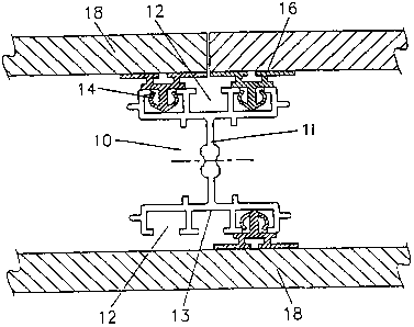
In the drawings, especially Figures 1 to 3, stud 10 has two
sets of three identical channels 12, each being "C" shaped, but
with a flat base 13. Channels 12 are shaped so that each
cooperating means 14 on joining clip 16, with relatively
resilient arms 14a and 14b (refer Figure 4), forms a hermetic
seal when pushed into channel 12.
In Figure 1, clip 16 is attached to panel 18 by gluing or other
suitable means. In Figure 2, however, clip 16 is attached to
panel 18 by pushing protrusion 20 into groove 22 in panel 18.
Extension 24 on clip 16 closes off gap 28 between panels 18.
Extension 24 may be of a softer material than the rest of clip
16.
Leg 30 on clip 16 (see Figure 3, for example) serves to space
panel 18 from stud 10.
In Figures 5 and 6, joining clip 116 has, as well as protrusion
20 and extension 28, cooperating means 15 with angled arm
portions 15a and 15b, designed to clip into channel 12, as
seen in Figure 6.
The joining clip 216 in Figures 7 and 8 is similar to clip 16
in Figure 1, in that it is attached to panels 18 by gluing
along surfaces 17. However, clip 216 in Figure 7 has the same
cooperating means 15 as clip 116 in Figure 5.
CA 02268410 1999-04-09
WO 98/16699 PCT/AU97/00681
-13-
The joining clip 316 in Figures 9 and 10 is particularly
suitable for imparting a finished appearance to abutting panels
18 and can provide added stability through extension 19.
Cooperating means 15 is the same as that in Figures 5 and 7.
Figures 11 and 12 show trim 21 with extension 25 which works
with extension 24 on clip 116 (see Figure 12) to close off gap
29 between panel 18 and extrusion 32. In addition, trim 21 fits
into gap 31 of decorative extrusion 32.
Figure 13 details how base 13 of centre channel 12 may be
painted; base 13 can be seen between panels 18 and its painted
colour may tone or contrast with that of panels 18.
Figure 14 shows the insertion of a moulding 23 in the gap
between panels 18.
In Figures 15 and 16, decorative extrusion 32 neatly ends the
wall system and provides a fixing facility for glass panel 34.
Figure 17 shows door 36 integrated with the wall system of the
invention but includes extrusion 38 which carries a channel 40
for a felt (not shown) or other insulating strip.
In Figure 18, panels 18 form a wall end with end panel 54. It
will be noted in this drawing that clips 216 are offset
relative to each other; this illustrates the versatility of the
stud of the present invention.
Figure 19 shows merely one arrangement of wall end and glass
panels 34.
Figure 20 illustrates how door 36 may be mounted between walls
using the system of the invention. Felt 62 is shown in channel
40 of extrusion 38.
Figure 21 shows how the same extrusion 38 may be used to
provide a rest at the top of door 36, in the form of felt or
^ 1
CA 02268410 1999-04-09
WO 98/16699 PCT/AU97/00681
-14-
rubber 62 in channel 40. Track 60 is attached to ceiling 61 and
also secures extrusion 38 and provides a mount for masking
clips 64. Each masking clip 64 has an arm 58 which is a push
fit into channel 57 in track 60.
In Figures 22 and 23, joining element 42 has protrusions 20
which fit into grooves 22 of panels 18. Joining element 42
permits panels 18 to form an external corner, so that faces 43
and 44 provide a neat finished appearance.
Hinge 46 connects faces 43. Because hinge 46 is resilient, it
allows panels 18 to adopt a configuration that is other than 90
degrees. This is useful to form both normal corners and unusual
angles; even normal corners are rarely at exactly 90 degrees,
and the joining element of the invention accommodates this
discrepancy.
In Figures 24 and 25, joining element 50 has protrusions 20
which fit into grooves or channels 22 in panels 18, which can
form an external corner. Hinge 52 connects faces 53. In the
external corner formed, hinge 52 provides a neat finished
appearance.
Figure 26 shows the same track 60 as in Figure 21, but this
time. panels 18 are supported by track 60, by hooking
protrusions 63 into gutters 59. The top ends 26 of panels 18
are covered by masking clips 64, with arms 58 push-fitted into
channels 57.
The lower ends 27 of panels 18 are also covered by masking
clips 64, arms 58 of which are a push-fit into channels 56 of
track 51. Track 51 is attached to floor 55.
Figure 27 has the same top arrangement as that in Figure 26.
However, the arrangement at the lower ends 27 of panels 18 is
different, in that instead of masking clips 64, skirting
extrusion 65 is attached to panels 18, either by gluing on
surface 66 or by screwing through notch 67.
, .__._. . ... . .._.....,...._T .. . , ., .. . . ... .......
CA 02268410 1999-04-09
WO 98/16699 PCT/AU97/00681
-15-
Turning now to Figures 28 to 31, bracket 70 is made of metal or
other suitable material or combinations of material, and has
shaft 71 inserted in sleeve 72. Shaft 71 is screw threaded for
all or the lower part of its length contained within sleeve 72.
Shaft 71 has a screw head 74 containing a slot 75 to accept the
blade of a screwdriver or other suitable tool.
Sleeve 72 has at one end cooperating means 73 and at the other
end a flange 76. As may be seen in Figure 29, cooperating
means 73 is shaped in end view to resemble a rectangle except
that one pair of opposing corners is cut off (refer 77 and 78).
Flange 76 has the same cross-sectional shape as cooperating
means 73.
As can be seen in Figure 30, cooperating means 73 can be
inserted horizontally into channel 12 of a stud 10, and then
rotated through 90 degrees to be retained in channel 12 as
shown in Figure 31. Screwing of shaft 71 towards base 13 of
channel 12 (by using a blade inserted in slot 75) will lock
bracket 70 into channel 12. Furniture components or other
items, including panels, may then be attached to shaft 71, as
desired.
The cross-sectional shape of flange 76 echoes that of
cooperating means 73, so that the orientation of cooperating
means in channel 12 can be ascertained.
Turning now to Figures 32 to 35, metal bracket 80 has two arms,
81 and 82, forming between them a right angle 83. Arm 81 has
cooperating means 84. Arm 82 has screw threaded extension 85,
for attaching furniture components or other building
components, as desired.
0-ring 86 mounted on arm 81 helps to ensure a snug fit of arm
81 within channel 12 (refer Figure 35).
Cooperating means 84 is generally rectangular in shape, except
that one corner is rounded off at 87. The purpose of this is
^ ^ i
CA 02268410 1999-04-09
WO 98/16699 PCT/AU97/00681
-16-
so that cooperating means 84 may be inserted in channel 12 of a
stud 10, in a similar manner to cooperating means 73 of bracket
70, then rotated horizontally through 90 degrees with the
assistance of rounded off corner 87, trapping bracket 80 in
channel 12. Bracket 80 may then be rotated vertically through
90 degrees, so that arm 81 is caused to lie substantially
within channel 12, o-ring 86 serving to wedge arm 81 in this
position.
It will be appreciated by one skilled in the art that a load
placed on arm 82 will enhance the locking of bracket 80 in
channel 12.
It will be readily appreciated by one skilled in the art that
cooperating means 14 in the embodiment shown in some of the
drawings (such as Figures 1, 2 and 3) has the considerable
advantage of sealing panel 18 hermetically, for the length of
the panel 18. This means that the system of the invention can
provide substantial insulation against transmission of noise
and the conductivity of heat and cold. There are also obvious
advantages in dealing with "wet" areas, such as bathrooms.
INDUSTRIAL APPLICABILITY
The building elements, brackets and track of the invention are
clearly a substantial advance in the art. The examples
referred to herein are illustrative and are not to be regarded
as limiting the scope of the invention.