Note: Descriptions are shown in the official language in which they were submitted.
CA 02269141 1999-04-26
._1_
NEGATIVE PRESSURE CONTROL APPARATUS FOR BRAKE
BOOSTER
BACKGROUND OF THE INVENTION
1. Field of the Invention
The present invention relates to a negative pressure
control apparatus for a brake booster, and particularly to a
negative pressure control apparatus for controlling negative
pressure of a brake booster which assists a brake operation by
using intake manifold negative pressure of a direct-injection
engine as a power source.
2. Description of the Related Art
Conventionally, as disclosed in Japanese Laid-Open
Patent Application No. 5-208663, a braking apparatus having a
brake booster is known. The brake booster is a mechanism which
assists a brake operation by using an intake manifold negative
pressure as a power source so that a larger braking force can
be generated.
Generally, in a case of a regular engine which
controls an opening of a throttle valve in accordance with an
acceleration operation, when a driver intends to decelerate a
vehicle, that is, when an accelerator pedal is not depressed,
the throttle valve is closed so that a relatively large intake
manifold negative pressure is generated. Thus, when the driver
performs a brake operation, the brake booster can be positively
operated.
The above-mentioned conventional braking
apparatus has a function of performing an automatic brake
control for generating a braking force irrespective of whether
or not a brake operation is performed when an obstacle is
detected ahead of the vehicle. In the above-mentioned
conventional braking apparatus, the brake booster is
CA 02269141 1999-04-26
- -2-
constructed so that it can generate a required braking force
when no brake operation is performed. However, if the automatic
brake control is performed when the driver intends to accelerate
the vehicle, that is, when the throttle valve is opened, the
intake manifold negative pressure is decreased. In this case,
the negative pressure in the brake booster may become
insufficient and the brake booster in the automatic brake
control may not generate the required braking force . In order
to avoid such a problem, the above conventional braking
apparatus generates an intake manifold negative pressure which
is sufficient for performing the automatic brake control by
forcibly closing the throttle valve when an establishment of
a condition for starting the automatic brake control is
predicted.
Conventionally, a direct-injection engine is known
which has a fuel injector disposed inside a combustion chamber
and directly injects fuel in the combustion chamber. According
to the direct-injection engine, fuel economy can be improved
by fully opening a throttle valve so that a pumping loss of the
engine is reduced when, for example, the engine is operating
under a low load. Thus, in the direct-injection engine, the
intake manifold negative pressure may be decreased by the
throttle valve being fully opened when an acceleration
operation is not being performed. Consequently, in a vehicle
having the direct-injection engine, the negative pressure in
the brake booster may become insufficient when the driver
intends to decelerate the vehicle.
However, the above-mentioned conventional braking
apparatus is adapted to be applied to the regular engine in which
a sufficient intake manifold negative pressure is generated by
the throttle valve being closed when a vehicle is decelerated.
Therefore, if the above-mentioned conventional braking
apparatus is applied to the direct-injection engine, a.t is
CA 02269141 1999-04-26
-3-
possible that a sufficient braking force cannot be generated
due to insufficient negative pressure in the brake booster when
the driver performs a brake operation.
SiJMMARY OF THE INVENTION
It is an object of the present invention to provide
a negative pressure control apparatus for a brake booster which
can always maintain a required negative pressure in the brake
booster in a system which includes a direct-injection engine.
The above object of the present invention can be
achieved by a negative pressure control apparatus for a brake
booster for controlling negative pressure in a negative
pressure chamber of the brake booster which can be connected
to an intake pipe of an engine at a position downstream of a
throttle valve, the comprising:
a brake operation predicting part for predicting
execution of a brake operation by a driver; and
a booster negative pressure controller for
controlling the negative pressure in the negative pressure
chamber to be a required value when execution of a brake
operation is predicted.
In this invention, negative pressure in the negative
pressure chamber of the brake booster is controlled to be a
required value when execution of a brake operation is predicted.
Thus, it is possible to maintain a sufficient negative pressure
in the negative pressure chamber of the brake booster for
assisting a brake operation in a system which includes a
direct-injection engine. Therefore, according to the
invention, a sufficient braking force can always be generated
when a brake operation is performed.
In this case, when a vehicle is running on a downhill
road, it can be judged that a driver is likely to perform a brake
operation so as to suppress an increase in a vehicle speed. Thus ,
CA 02269141 1999-04-26
_4_
the brake operation predicting part may predict execution of
a brake operation when a vehicle is running on a downhill road.
Additionally, when a vehicle behavior control such
as a vehicle stability control ( VSC ) or a traction control ( TRC )
for controlling a behavior of a vehicle is being performed, it
can be judged that a driver is likely to perform a brake operation
so as to decelerate the vehicle. Thus, the brake operation
predicting part may predict execution of a brake operation when
the vehicle behavior control is being performed.
Additionally, when a between-car time to a car
running ahead (that is, a value obtained by dividing a distance
to a vehicle running ahead by an approaching speed relative to
that car) is small, it can be judged that the driver is likely
to perform a brake operation so as to avoid a contact with the
car running ahead. Thus, the brake operation predicting part
may predict execution of a brake operation when the between-car
time to a car running ahead is smaller than a predetermined
value.
Additionally, when a vehicle is running towards a
crossing or a freeway exit, it can be judged that a driver is
likely to decelerate the car. Thus, the brake operation
predicting part may predict execution of a brake operation when
a vehicle is running towards a crossing or a freeway exit
Additionally, a driver performs a shift-down
operation when he intends to decelerate a car. In this case,
it can be judged that the driver is likely to perform a brake
operation. Thus, the brake operation predicting part may
predict execution of a brake operation when a driver performs
a shift-down operation.
Similarly, a driver releases a depression of an
accelerator pedal at a high speed when he intends to decelerate
a vehicle. Thus, the brake operation predicting part may
predict execution of a brake operation when a depression of an
CA 02269141 1999-04-26
-5-
accelerator pedal is being released at a speed greater than a
predetermined value.
Further, when a driver shifts a shift lever to a
neutral position or shifts a select lever to an N range, it can
be judged that the driver is likely to intend to stop a vehicle.
Thus , the brake operation predicting part may predict execution
of a brake operation when the shift lever is in a neutral position
or the select lever is in an N range.
Additionally, the negative pressure in an intake
passage downstream of a throttle valve changes in accordance
with an opening of the throttle valve. Thus, the negative
pressure controller may control the negative pressure in the
negative pressure chamber of the brake booster by changing the
opening of the throttle valve.
Other objects and further features of the present
invention will be apparent from the following detailed
description when read in conjunction with the accompanying
drawings.
BRT_EF DESCRIPTION OF THE DRAWINGS
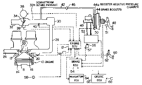
Fig.l is a system structure diagram of an embodiment
of the present invention;
FIG.2 is a flowchart of an example of a routine
performed by a brake ECU in the present embodiment;
FIG.3 is an example of a map referred to by the brake
ECU so as to determine a required-negative-pressure value; and
FIG.4 is a flowchart of an example of a routine
performed by an engine ECU in the present embodiment.
nFSC'RTpTTON OF THE PREFERRED EMBODIMENTS
FIG.1 shows a system structure diagram of an
embodiment according to the present invention. The system of
the present embodiment is provided on a vehicle. As shown in
CA 02269141 1999-04-26
4
-6-
FIG.1, the system includes an engine 10. The engine 10 is
controlled by an engine ECU 12. The engine 10 has a cylinder
block 13. A cylinder 14 is formed inside the cylinder block
13. The engine 10 has a plurality of cylinders and only one
cylinder 14 is shown in FIG.1.
A piston 16 is disposed in the cylinder 14. The
piston 16 can move vertically in the cylinder 14. A combustion
chamber 18 is defined inside the cylinder 14 above the piston
16. An injection port of a fuel injector 20 is exposed in the
combustion chamber 18. The fuel injector 20 injects fuel in
the combustion chamber 18 in response to a control signal
supplied by the engine ECU 12. That is, the engine 10 of the
present embodiment is a direct-injection engine.
An exhaust pipe 24 is connected to the combustion
chamber 18 via an exhaust valve 22. Additionally, an intake
manifold 28 is connected to the combustion chamber 18 via an
intake valve 26. A surge tank 30 is connected to an upstream
side of the intake manifold 28. Further, an intake pipe 32 is
connected to an upstream side of the surge tank 30.
A throttle valve 34 is disposed in the intake pipe
32. The throttle valve 34 is connected to a throttle motor 36.
The throttle motor 36 is electrically connected to the engine
ECU 12 . The throttle motor 36 changes an opening of the throttle
valve 34 (hereinafter referred to as a throttle opening SC) in
response to a control signal supplied by the engine ECU 12. A
throttle-opening sensor 38 is disposed near the throttle valve
34. The throttle-opening sensor 38 delivers an electric signal
in accordance with the throttle opening SC to the engine ECU
12. The engine ECU 12 detects the throttle opening SC based
on the signal delivered by the throttle-opening sensor 38.
An intake-pressure sensor 40 is disposed in the
intake pipe 32 at a position downstream of the throttle valve
34. Hereinafter, this part of the intake pipe 32 is referred
CA 02269141 1999-04-26
_7_
to as a downstream intake passage 32a. The intake-pressure
sensor 40 delivers an electric signal to the engine ECU 12 in
accordance with a negative pressure in the downstream intake
passage 32a (hereinafter referred to as an intake manifold
negative pressure PM). The engine ECU 12 detects the intake
manifold negative pressure PM based on the signal delivered by
the intake-pressure sensor 40.
One end of a negative pressure supply passage 42 is
connected to the downstream intake passage 32a. The other end
of the negative pressure supply passage 42 is connected to a
negative pressure chamber of a brake booster 44. Hereinafter,
the negative pressure chamber of the brake booster 44 is referred
to as a booster negative pressure chamber 44a.
A check valve 46 is disposed in the negative pressure
supply passage 42. The check valve 46 is a one-way valve which
permits a flow of air only in a direction from the booster
negative pressure chamber 44a to the downstream intake passage
32a. Thus, when the intake manifold negative pressure PM is
larger than a negative pressure in the booster negative pressure
chamber 44a (hereinafter referred to as a booster negative
pressure PB), the booster negative pressure PB is increased
until it is equalized with the intake manifold pressure PM. On
the other hand, when the intake manifold negative pressure PM
is smaller than the booster negative pressure PB, air is
prevented from flowing from the downstream intake passage 32a
to the booster negative pressure chamber 44a, and thus the
booster negative pressure PB is prevented from being decreased.
It should be noted that , in the present specification,
a "negative pressure" is represented by a pressure difference
relative to the atmospheric pressure. Thus, an expression that
"a negative pressure is large" means that the pressure
difference relative to the atmospheric pressure is large, that
is, an absolute pressure is low.
CA 02269141 1999-04-26
_8_
The brake booster 44 is connected to a brake pedal
48 and a master cylinder 49. The brake booster 44 assists an
operation of the brake pedal 48 by using the booster negative
pressure PB as a power source so that a higher fluid pressure
is generated in fluid chambers of the master cylinder 49.
Hereinafter, the fluid pressure generated in the fluid chambers
of the master cylinder 49 is referred to as a master cylinder
pressure PM,c
A booster pressure sensor 50 is disposed in the
booster negative pressure chamber 44a. The booster pressure
sensor 50 delivers an electric signal to the engine ECU 12 in
accordance with the booster negative pressure PB. The engine
ECU 12 detects the booster negative pressure PB based on the
signal delivered by the booster pressure sensor 50.
A brake switch 51 is disposed near the brake pedal
48. The brake switch 51 delivers an ON signal to the brake ECU
54 only when the brake pedal 48 is depressed. The ECU 54
determines whether or not a brake operation is performed based
on the signal delivered by the brake switch 51.
A hydraulic actuator 52 is connected to the fluid
chambers of the master cylinder 49. The hydraulic actuator 52
is controlled by the brake ECU 54. Wheel cylinders 56 provided
to the respective wheels are connected to the hydraulic actuator
52. Wheel speed sensors 57 are disposed near the respective
wheels . In FIG .1, only the wheel cylinder 56 and the wheel speed
sensor 57 for one of the wheels are shown. Each of the wheel
speed sensors 57 delivers a pulse signal to the brake ECU 54
in accordance with a wheel speed VW. The brake ECU 54 detects
the wheel speed VW based on the signals delivered by the wheel
speed sensors 57. The brake ECU 54 calculates a wheel
acceleration DVW based on a change rate of the wheel speed VW.
Further, the brake ECU 54 calculates a vehicle speed V based
on the wheel speed VW.
CA 02269141 1999-04-26
The hydraulic actuator 52 can perform a regular brake
control for generating a braking force in accordance with a brake
operation and a vehicle behavior control for generating a
braking force in accordance with a behavior of a vehicle
regardless of the brake operation. In the present embodiment,
the regular brake control is achieved by supplying the master
cylinder pressure P"~~ to the wheel cylinders 56. On the other
hand, the vehicle behavior control is achieved by appropriately
operating solenoid valves provided to the hydraulic actuator
52 so as to supply a required fluid pressure to each of the wheel
cylinders 56. It should be noted that the vehicle behavior
control includes a vehicle stability control (VSC) and a
traction control (TRC).
The VSC is a control for stabilizing a behavior of
a vehicle. The brake ECU 54 starts the VSC when an unstable
behavior of the vehicle is detected based on information such
as a steering angle, a lateral acceleration of each wheel, a
yaw rate, a deceleration, and a slip rate of each wheel. In
the VSC, the brake ECU 54 controls the hydraulic actuator 52
to provide an appropriate braking force to each wheel so that
the behavior of the vehicle is stabilized.
The TRC is a control for preventing a slip due to
an excessive driving torque of a wheel (hereinafter referred
to as a driving slip). The brake ECU 54 starts the TRC when
a driving slip is detected. In the TRC, the brake ECU 54 controls
the hydraulic actuator 52 to provide an appropriate braking
force to each wheel so that the driving slip is cancelled.
As shown in FIG.1, a revolution sensor 58 is provided
to the engine 10. The revolution sensor 58 delivers a pulse
signal to the engine ECU 12 in accordance with a rotational speed
Ne of the engine 10. The engine ECU 12 detects the rotational
speed Ne based on the signal delivered by the revolution sensor
58.
CA 02269141 1999-04-26
-10-
A shift-position sensor 59 is electrically connected
to the brake ECU 54. The shift-position sensor 59 delivers an
electric signal to the brake ECU 54 in accordance with a position
of a shift lever (or a select lever, in case of a automatic
transmission vehicle ) of the vehicle . The brake E.CU 54 detects
the position of the shift lever (or a range of the select lever)
based on the signal delivered by the shift-position sensor 59.
An accelerator-opening sensor 62 is provided near
an accelerator pedal 60. The accelerator-opening sensor 62
delivers an electric signal to the engine ECU 12 in accordance
with a stroke of the accelerator pedal 60 (hereinafter referred
to as an accelerator opening AC). The engine ECU 12 detects
the accelerator opening AC based on the signal delivered by the
accelerator opening sensor 62.
A navigation ECU 64 is electrically connected to the
engine ECU 12. The navigation ECU 64 is a control unit for
controlling an automobile navigation system provided on the
vehicle. The navigation ECU 64 transmits information regarding
a current position of the vehicle to the engine ECU 12.
Additionally, a cruise ECU 66 is electrically
connected to the brake ECU 54. The cruise ECU 66 is a control
unit for controlling a radar cruise of the vehicle. A radar
unit 68 is electrically connected fio the cruise ECU 66. The
radar unit 68 is a distance sensor such as an ultrasonic sensor
or an optical sensor for sensing a distance to a vehicle running
ahead. The cruise ECU 66 detects the distance to the vehicle
running ahead based on an output signal of the radar unit 68
and transmits information regarding the detected distance to
the brake ECU 54.
In the present embodiment, the engine 10 operates
in one of a stoichiometric combustion mode and a stratified
charge combustion mode in accordance with a load thereof. In
the stoichiometric combustion mode, a stoichiometric
CA 02269141 1999-04-26
~- 11-
combustion is achieved in the combustion chamber 18 by changing
the throttle opening SC based on the accelerator opening AC so
that the volume of air supplied to the combustion chamber 18
is controlled in accordance with the acceleration opening AC.
In the stratified charge combustion mode, a stratified charged
combustion is achieved in the combustion chamber 18 by fully
opening the throttle valve 34 so that a large volume of air is
supplied to the combustion chamber 18 and by injecting a quantity
of fuel corresponding to the accelerator opening AC during
compression strokes of the engine 10.
According to the stratified charged combustion mode,
a fuel economy is improved because a larger air-fuel ratio is
achieved in the combustion chamber 18 as compared to a case of
the stoichiometric combustion mode. Additionally, the fuel
economy is further improved in the stratified charge combustion
mode because a pumping loss of the engine 10 is reduced by the
throttle valve 34 being fully opened. Therefore, from a
viewpoint of improving the fuel economy, it is desirable to
operate the engine 10 in the stratified charge combustion mode.
However , when a load of the engine 10 ( that is , the
acceleration opening AC) is increased, a quantity of fuel
injected by the fuel injector 20 becomes large. In this case,
the stratified charge combustion can no longer be achieved when
the injection quantity exceeds a certain value, because a volume
of air supplied to the intake pipe 32 ( that is , a specific volume
of intake air Q) becomes too small as compared to the injection
quantity even if the throttle valve 34 is fully opened.
For the above reasons , the engine ECU 12 calculates
the injection quantity based on the accelerator opening AC and
determines whether or not the stratified charge combustion can
be achieved with the calculated injection quantity. When it
is determined that the stratified charge combustion can be
achieved, the engine ECU 12 achieves the stratified charge
CA 02269141 1999-04-26
-12-
combustion mode by fully opening the throttle valve 34 and
controlling the injector 20 to inject a quantity of fuel
corresponding to the accelerator opening AC during compression
strokes of the engine 10 . On the other hand, if it is determined
that the stratified charge combustion cannot be achieved, the
engine ECU 12 achieves the stoichiometric combustion mode by
setting the throttle opening SC to be a value corresponding to
the accelerator opening AC and controlling the injector 20 to
inject a quantity of fuel corresponding to the throttle opening
SC during intake strokes of the engine 10.
As mentioned above, in the stratified charge
combustion mode, the throttle valve 34 is fully opened
regardless of the accelerator opening AC. When the throttle
valve 34 is fully opened, the negative pressure generated in
the downstream intake passage 32a ( that is , the intake manifold
negative pressure PM) becomes small. Additionally, the brake
booster 44 assists a brake operation by using the booster
negative pressure PB as a power source, and thus the booster
negative pressure PB is decreased more as the braking force
becomes larger. Therefore, in the stratified charge combustion
mode, since a sufficient negative pressure cannot be supplied
from the downstream intake pipe 32a to the booster negative
pressure chamber 44a, the booster negative pressure PB is
gradually decreased in association with the brake operation.
For this reason, if a brake operation is performed when the
engine 10 is operating in the stratified charge combustion mode,
it is possible that the brake booster 44 cannot sufficiently
assist the brake operation due to the insufficient booster
negative pressure PB.
According to the present embodiment, in order to
avoid such a problem, in a situation where no brake operation
is performed and a brake operation is expected to be performed,
the throttle opening SC is reduced and, if necessary, the
CA 02269141 1999-04-26
' -13-
operation mode of the engine 10 is switched from the stratified
charge combustion mode to the stoichiometric combustion mode,
so that a brake booster negative pressure PB required to
positively operate the brake booster is obtained.
When the throttle opening is reduced, the intake
manifold negative pressure PM is increased. Additionally, when
the throttle opening is reduced, it is possible that the
stratified charge combustion cannot be maintained since the
specific volume of intake air Q may be decreased so as to be
insufficient for the injection quantity. As mentioned above,
in the stoichiometric combustion mode, the throttle opening SC
is controlled to be a value corresponding to the accelerator
opening AC. Thus, when the stratified charge combustion cannot
be maintained, the intake manifold negative pressure PM can be
increased by switching the operation mode of the engine 10 to
the stoichiometric combustion mode, because the throttle
opening SC is reduced as long as the accelerator pedal 60 is
not fully depressed.
In this way, it is possible to always maintain a
sufficient booster negative pressure PB by reducing the
throttle opening SC or switching the operation mode of the engine
10 to the stoichiometric combustion mode so that the intake
manifold negative pressure PM is increased. Hereinafter, the
above control for increasing the intake manifold negative
pressure PM is referred to as a booster negative pressure
control.
It should be noted that, if the booster negative
pressure control is executed while a brake operation is being
performed, the brake pedal 48 is pulled into the brake booster
44 due to a rapid increase in the booster negative pressure PB.
In this case, an excessive deceleration may be generated. To
avoid such a problem, in the present embodiment, the booster
negative pressure control is executed only in a situation where
CA 02269141 1999-04-26
- 14-
no brake operation is performed and a brake operation is expected
to be performed.
In the present embodiment , when no brake operation
is performed and a brake operation is expected to be performed,
the brake ECU 54 transmits a negative-pressure-requiring signal
to the engine ECU 12 indicating a value of negative pressure
to be supplied to the booster negative pressure chamber 44a
(hereinafter referred to as a required-negative-pressure value
Pr~). When the engine ECU 12 receives the negative-
pressure-requiring signal from the brake ECU 54, it performs
the booster negative pressure control so as to generate an intake
manifold negative pressure PM equal to the required-
negative-pressure value Pr~. Additionally, the engine ECU 12
transmits a signal indicating the booster negative pressure PB
and the accelerator opening AC to the brake ECU 54 at appropriate
timings. Further, the brake ECU 54 transmits a maximum-
negative-pressure-requiring signal to the engine ECU 12 when
a failure has occurred in a brake system of the vehicle.
Now, a detailed description will be given of the
processes performed by the brake ECU 54 and the engine ECU 12
so as to achieve the above-mentioned booster negative pressure
control. First, a description will be given of the process
performed by the brake ECU 54 with reference to FIG.2. FIG.2
is a flowchart of an example of a routine performed by the brake
ECU 54 so as to transmit the negative-pressure-requiring signal
to the engine ECU 12. The routine shown in FIG.2 is repeatedly
started every time when one process cycle thereof is finished.
When the routine shown in FIG.2 is started, the process of step
100 is performed first.
In step 100 , it is determined whether or not a failure
has occurred in the brake system. If a failure has occurred
in the brake system, it is determined that a booster negative
pressure PB as large as possible should be generated. In this
CA 02269141 1999-04-26
-15-
case, the maximum-negative-pressure-requiring signal is
transmitted to the engine ECU 12 in step 101, and then the present
routine is ended. On the other hand, if no failure has occurred
in the brake system, then the process of step 102 is performed.
In step 102 , it is determined whether or not a brake
operation is being performed based on the output signal of the
brake switch 51. If a brake operation is being performed, it
is determined that the booster negative pressure control should
not be performed, and then the present routine is ended. On
the other hand, if no brake operation is being performed in step
102, then the process of step 103 is performed.
In step 103, the booster negative pressure PB is
detected based on the signal transmitted from the engine ECU
12.
In step 104, it is determined whether or not the
booster negative pressure PB is smaller than a predetermined
value P0. The predetermined value PO is a minimum value of the
booster negative pressure PB which should always be maintained.
Thus, if it is determined that PB is smaller than P0, then in
step 105, the required-negative-pressure value Pr~ is set to
be the predetermined value P0. On the other hand, if it is
determined that PB is not smaller than P0, then in step 106 and
subsequent steps, processes are performed for determining
whether or not a brake operation is expected to be performed.
In step 106, it is determined whether or not the
vehicle is running on a downhill road. When a vehicle is running
on a downhill road, a larger acceleration is generated for a
constant engine power as compared to a case where the vehicle
is running on a flat or uphill road. Thus, the brake ECU 54
uses the accelerator opening AC and the wheel acceleration DVW
as values representing the engine power and the vehicle
acceleration, respectively, and if the wheel acceleration DVW
is larger than a reference value corresponding to the
CA 02269141 1999-04-26
-16-
accelerator opening AC, the brake ECU 54 determines that the
vehicle is running on a downhill road. When the vehicle is
running on a downhill road, it can be judged that the driver
is likely to perform a brake operation so as to suppress an
increase in the vehicle speed V . Thus , if it is determined that
the vehicle is running on a downhill road in step 106, it is
judged that a brake operation is expected to be performed, and
then the process of step 108 is performed. On the other hand,
if it is determined that the vehicle is not running on a downhill
road in step 106, then the process of step 110 is performed.
In step 110 , it is determined whether or not the VSC
or the TRC is being performed. As mentioned above, the VSC is
performed when an unstable behavior has occurred in the vehicle .
When an unstable behavior has occurred in the vehicle, it can
be judged that the driver is likely to perform a brake operation
so as to stabilize the behavior of the vehicle . Additionally,
the TRC is performed when a driving slip is generated due to
an excessive driving torque. Thus, when the TRC is being
performed, it can be judged that the VSC is likely to be started
due to an unstable behavior of the vehicle caused by the driving
slip. Thus, if it is determined that the VSC or the TRC is
performed in step 110, it is judged that a brake operation is
expected to be performed and then the process of step 108 is
performed. On the other hand, if neither the TRC nor the VSC
is being performed in step 110, the process of step 112 is
performed.
In step 112, it is determined whether or not a
decreasing rate AV of the accelerator opening AC is greater than
a predetermined value AVO . When a depression of the accelerator
pedal 60 is being rapidly released, it can be judged that the
driver intends to decelerate the vehicle due to, for example,
an occurrence of an obstacle ahead of the vehicle. Thus, if
it is determined that AV is greater than AVO , it is judged that
CA 02269141 1999-04-26
:17_
a brake operation is expected to be performed and then the
process of step 108 is performed. On the other hand, if AV is
not greater than AVO in step 112 , then the process of step 114
is performed.
In step 114, it is determined whether or not a
between-car time Tc is smaller than a predetermined value T0.
The between-car time Tc is a value obtained by dividing a
distance to a car running ahead by a relative approaching speed
to that car. That is, the between-car time is a time until a
contact with the car running ahead occurs when the current
relative approaching speed is maintained. When the between-car
time Tc becomes small, it can be judged that the driver is likely
to perform a brake operation so as to avoid a contact with the
car running ahead. Thus, if Tc is smaller than TO in step 114,
it is judged that a brake operation is expected to be performed,
and then the process of step 108 is performed. On the other
hand, if Tc is not smaller than T0, then the process of step
116 is performed.
In step 116, it is determined whether or not the
vehicle is running towards a crossing or a freeway exit and the
vehicle speed V is greater than or equal to a predetermined value
V0. The determination whether or not the vehicle is running
towards a crossing or a freeway exit is performed based on the
position information transmitted by the navigation ECU 64.
When the vehicle is running towards a crossing or a freeway exit
with a speed greater than a certain speed, it can be judged that
the driver is likely to perform a brake operation so as to
decelerate the vehicle. Thus, if it is affirmatively
determined in step 116 , it is judged that a brake operation is
expected to be performed and then the process of step 108 is
performed. On the other hand, if it is negatively determined
in step 116, then the process of step 118 is performed.
In step 118, it is determined whether or not a
CA 02269141 1999-04-26
-18-
shift-down operation is performed by the driver. Generally,
a shift-down operation is performed when a driver intends to
decelerate the vehicle. Therefore, when a shift-down operation
is performed, it can be judged that the driver is likely to
perform a brake operation. Thus, if it is determined that a
shift-down operation is performed in step 118, it is judged that
a brake operation is expected to be performed and then the
process of step 108 is performed. On the other hand, if it is
determined that the shift-down operation is not performed in
step 118, then the process of step 120 is performed. It should
be noted that the shift-down operation in the present invention
includes a shift-down operation in an automatic transmission
(AT) car (for example, an operation of shifting a select lever
from a D3 range to a D2 range) as well as a shift-down operation
in a manual transmission (MT) car.
In step 120, it is determined whether or not a shift
lever is in a neutral position (or a select lever is in an N
range in case of an AT car) and the vehicle speed V is greater
than or equal to a predetermined value Vl. Generally, when a
shift lever is shifted to a neutral position or a select lever
is shifted to an N range, it can be judged that the driver is
likely to intend to stop the vehicle. Thus, if it is
affirmatively determined in step 120 , it is judged that a brake
operation is expected to be performed and then the process of
step 108 is performed. On the other hand, if it is negatively
determined in step 120, this means that it is negatively
determined in all of steps 106 and 110 to 120. In this case,
it is judged that a brake operation is not expected to be
performed and the present routine is ended.
In step 108, it is determined whether or not the
vehicle speed V is greater than a predetermined value Vc . The
predetermined value Vc is a maximum value of such a vehicle speed
V that, once the booster negative pressure PB equal to the
CA 02269141 1999-04-26
-19-
minimum value PO is generated, the brake booster 44 can continue
to assist a brake operation until the vehicle stops, in a
situation where the throttle opening SC is not further decreased.
Thus, when V is not greater than Vc, it is determined that the
booster negative pressure control need not be performed and the
present routine is ended. On the other hand, if V is greater
than Vc in step 108, then the process of step 122 is performed.
In step 122, the required-negative-pressure value
P=te is set . The required-negative-pressure value P=te is set to
be a minimum value of the booster negative pressure PB which
is sufficient for the brake booster 44 to assist a brake
operation until the vehicle stops in a situation where no
negative pressure is supplied to the booster negative pressure
chamber 44a.
FIG.3 shows an example of a map which is referred
to by the brake ECU 54 so as to set the required-negative-
pressure value Pr~ based on the vehicle speed V in step 122.
As mentioned above, the booster negative pressure
PB is consumed as a braking force increases. Additionally, a
braking force, which is generated at a time when the vehicle
is to stop, becomes larger as the vehicle speed V becomes higher.
Thus, as the vehicle speed becomes higher, the booster negative
pressure PB is consumed to a greater extent until the vehicle
stops. In other words, as the vehicle speed becomes higher,
a value of the booster negative pressure PB is increased, which
value should be maintained so as to operate the brake booster
44 to assist a brake operation until the vehicle stops without
supplying a.ny negative pressure to the booster negative
pressure chamber 44a. For this reason, as shown by a curve in
FIG.3, when the vehicle speed V is smaller than or equal to a
predetermined value Vc, the required-negative-pressure value
Preq is set to be equal to the reference value P0, and when the
vehicle speed V exceeds the predetermined value Vc, the
CA 02269141 1999-04-26
-20-
required-negative-pressure value Pr,q is set to be a greater
value as the vehicle speed V increases.
After the required-negative-pressure value P=eQ is
set in step 122 or 105, the negative-pressure-requiring signal
indicating the required-negative-pressure value.Pr,q is
transmitted to the engine ECU 12 in step 124. When the process
of step 124 is finished, the present routine is ended.
Now, a description will be given of a process
performed by the engine ECU 12 in the present embodiment . FIG. 4
shows a flowchart of an example of a routine performed by the
engine ECU 12 so as to achieve the booster negative pressure
control in the present embodiment. The routine shown in FIG.4
is repeatedly started every time when one cycle process thereof
is finished. When the routine shown in FIG.4 is started, the
process of step 150 is performed first.
In step 150, it is determined whether or not the
engine 10 is operating in the stratified charge combustion mode .
If it is negatively determined, that is, if the engine 10 is
operating in the stoichiometric combustion mode, it is judged
that the booster negative pressure control cannot be performed
without decreasing the power of the engine 10. In this case,
no further process is performed thereafter and the present
routine is ended. On the other hand, if the engine 10 is
operating in the stratified charge combustion mode in step 150,
then the process of step 151 is performed.
In step 151, it is determined whether or not the
maximum-negative-pressure-requiring signal is transmitted by
the brake ECU 54. If the maximum-negative-pressure-requiring
signal is transmitted, then the operation mode of the engine
10 is switched to the stoichiometric combustion mode in step
152. As mentioned above, when the operation mode of the engine
10 is switched to the stoichiometric combustion mode, the
throttle opening SC is reduced and a larger intake manifold
CA 02269141 1999-04-26
-21-
negative pressure PM is generated. When the process of step
152 is finished, the present routine is ended. On the other
hand, if the maximum-negative-pressure-requiring signal is not
transmitted in step 151, then the process of step 154 is
performed.
In step 154, it is determined whether or not the
engine 10 is being warmed up. As mentioned above, the throttle
opening SC is reduced when the booster negative pressure control
is performed. Thus, if the booster negative pressure control
is performed during the warm-up of the engine 10, the engine
10 cannot be adequately warmed up. Thus, if the engine 10 is
being warmed up in step 154, the engine ECU 54 determines that
the booster negative pressure control should not be performed
and ends the present routine, giving priority to the warm-up
of the engine 10. On the other hand, if the engine 10 is not
being warmed up in step 154, then the process of step 156 is
performed .
In step 156, it is determined whether or not the
negative-pressure-requiring signal is being transmitted from
the brake ECU 54. If the negative-pressure-requiring signal
is not being transmitted, then the present routine is ended.
On the other hand, if the negative-pressure-requiring signal
is being transmitted in step 156 , then the process of step 158
is performed.
In step 158, a value of the throttle opening SC for
generating an intake manifold negative pressure PM equal to the
required-negative-pressure value PrgQ (hereinafter, this value
of the throttle opening SC is referred to as a target throttle
opening SCc) is determined. The intake manifold negative
pressure PM increases as the specific volume of intake air Q
becomes smaller and the rotational speed Ne becomes greater.
Additionally, the specific volume of intake air Q is
substantially proportional to the throttle opening SC. Thus,
CA 02269141 1999-04-26
. , -22-
in step 158, the target throttle opening SCc is determined based
on the rotational speed Ne and the required-negative-pressure
value Pry. When the process of step 158 is finished, then the
process of step 160 is performed.
In step 160, a value QO of the specific volume of
intake air Q corresponding to the target throttle opening SCc
is calculated. In the subsequent step 162, a value F of the
injection quantity corresponding to the accelerator opening AC
in the stratified charge combustion mode ( that is , a value of
the injection quantity which is necessary to achieve the engine
power required by a driver) is calculated. It should be noted
that an injection quantity necessary to achieve a constant
engine power increases when the throttle opening SC is decreased
to the target throttle opening SCc due to an increase in the
pumping loss. In step 162, such an influence of the increase
in the pumping loss is taken into consideration in calculating
the injection quantity F. When the process of step 162 is
finished, then the process of step 164 is performed.
In step 164, it is determined whether or not the
stratified charge combustion mode can be maintained with the
specific volume of intake air QO and the injection quantity F
while maintaining the current rotational speed Ne. If it is
determined that the stratified charge combustion can be
maintained, then in step 166, the throttle opening SC is
decreased to the target throttle opening SCc. After the process
of step 166 is performed, the intake manifold negative pressure
PM starts being increased toward the required-negative-
pressure value Pr~. In the subsequent step 168, it is determined
whether or not the intake manifold negative pressure PM has
reached the required-negative-pressure value P=eQ. If it is
negatively determined in step 168 , then the process of step 168
is performed again. On the other hand, if it is affirmatively
determined in step 168, then the process of step 170 is
CA 02269141 1999-04-26
- ~ -23-
performed .
In step 170, the throttle valve 34 is fully opened
again and the injection quantity is decreased by a value
corresponding to a decrease in the pumping loss due to the
increase in the throttle opening SC . When the process of step
170 is finished, then the present routine is ended.
On the other hand, if, in step 164, it is determined
that the stratified charge combustion mode cannot be maintained,
then the operation mode of the engine 10 is switched to the
stoichiometric combustion mode in step 172. In the
stoichiometric combustion mode, a larger intake manifold
negative pressure PM is generated as compared to a case of the
stratified charge combustion mode because the throttle opening
SC is decreased to a value corresponding to the accelerator
opening AC. Therefore, after the process of step 172 is
performed, the intake manifold negative pressure PM starts
being increased.
In the subsequent step 174 , it is determined whether
or not the intake manifold negative pressure PM has reached the
required-negative-pressure value PrgQ. If it is negatively
determined in step 174 , then the process of step 174 is performed
again. On the other hand, if it is affirmatively determined
in step 174, then the process of step 176 is performed.
In step 176 , the operation mode of the engine 10 is
returned to the stratified charge combustion mode. When the
process of step 176 is finished, the present routine is ended.
According to the routine shown in FIG.4, an intake
manifold negative pressure equal to the required-negative-
pressure value P~ can be generated. As mentioned above, the
required-negative-pressure value Prgq is set to be a minimum
value of the booster negative pressure PB which can positively
operate the brake booster 44 until the vehicle stops in a
situation where no negative pressure is supplied to the booster
CA 02269141 1999-04-26
. - 24 -
negative pressure chamber 44a from the downstream intake
passage 32a. Thus, once the intake manifold negative pressure
PM equal to the required-negative-pressure value Pr~ is
generated and this negative pressure is supplied to the booster
negative pressure chamber 44a, the brake booster 44 can
positively assist a brake operation until the vehicle stops.
In this way, when a brake operation is expected to
be performed, it is possible to obtain a booster negative
pressure PB which is required to operate the brake booster 44
until the vehicle stops. Thus, according the present
embodiment, it is possible to generate a sufficient braking
force until the vehicle stops in the system including the engine
10 constructed as a direct-injection engine.
It should be noted that the negative pressure supply
passage 46 may be connected to the surge tank 30 or the intake
manifold 28 instead of the downstream intake passage 32a.
Further, the present invention is not limited to the
embodiment, but variations and modifications may be made
without departing from the scope of the present invention.