Note: Descriptions are shown in the official language in which they were submitted.
CA 02269230 1999-04-19
WO 98/19846 PCT/CA97/00827
1
APPARATUS FOR AND METHOD OF INJECTION MOLDING
FIELD OF THE INVENTION
This invention relates to an apparatus for and a method of injection
molding articles from plastic, and more particularly is concerned with the
molding of high quality articles requiring an accurate hole or aperture
through the article, without any weld lines. This invention is more
particularly intended for use in molding generally circular articles such as
optical or magnetic discs, or precision gears.
BACKGROUND OF THE INVENTION
The molding of objects with apertures or holes, for example, gears,
wheels, etc. with a central hole, has always presented problems. Often,
such a part is molded by injecting plastic from at least one side of a mold
cavity. This will often result in weld lines being formed of plastic material,
as when the molten plastic flows through the cavity and around the
metallic core that forms a hole or aperture in the object. For many
purposes, this can be tolerated, and by appropriate selection of injection
conditions, the effect of weld lines can be minimized and accepted.
More recently, there are new classes of articles, for which much
higher tolerances and uniformity are required. In particular, there is a
growing demand for optical discs. These have a disc substrate formed
from a synthetic resin, such as a light-transmitting polycarbonate resin. A
read only disc has a spiral track with a series of recesses and lands
encoding desired information, which can be a musical sound signal, an
optical image, or digital information. A reflective film, produced for
example, by vacuum deposition of aluminum is provided. The information
is read by reflection of a laser beam from the recesses and lands. This
requires the disc not only to have uniform mechanical properties but also
to have extremely uniform optical properties. In current discs for recording
musical sound and the like, known as compact discs or CDs, the pits have
a certain size. More recently, it has been proposed to use the same
technique for digitally encoding video signals, with pits having a much
smaller dimension to enable more information to be encoded, and such
CA 02269230 1999-04-19
WO 98/19846 PCT/CA97/00827
2
discs are known as Digital Versatile (Video) Discs (DVDs), which may be
double sided. With such small dimensions, it is essential to have
consistent and uniform optical characteristics.
More particularly, any variation in the refractive index is wholly
unacceptable. This can result from material used to manufacture any
individual disc having a wide variety of shear history throughout. Also,
weld lines can cause birefringence problems, which again are
unacceptable. Similar considerations apply to a magneto-optical disc,
capable of rewriting information signals.
This problem has been recognized, at least for recording discs of
the type described above. A common feature of proposals for molding
such discs is to inject the plastic through a nozzle located on the axis of
the disc. Plastic first flows axially and then turns 90° at a gate to
flow
radially outwardly. The intention is that the plastic will fill the cavity
uniformly, avoid weld lines, and avoid complex and non-uniform shear
history in the material. However, these characteristics have not always
been obtained to date, and often other problems are generated.
RELATED ART
The disclosures of all references mentioned in this description are
incorporated herein by reference.
US Patent 2,698,464 issued to Wilson describes a double cavity
mold to form record discs having a central hole. This design shows a
freely moving pin element that has two functions: it seals the machine
injection nozzle and it creates the hole during its back move towards the
machine nozzle. This pin element of Wilson '464 does not act as a mold
core, does not act as a mold gate and does not guide or direct the flow of
the molten resin radialiy or in any other manner towards the cavity. As a
major drawback, the movement of the pin element backward after injection
will redirect the injected material from the mold main channel back into the
already filled mold cavities and also back into the machine nozzle. This
approach is unacceptable when molding information carrier discs as the
extra material will create weld lines with the initially filled material. Also
the
CA 02269230 1999-04-19
WO 98/19846 PCT/CA97/00827
mold injection nozzle of Wilson '464 is stationary and does not have a tip
portion with a gating portion to form a circular gate of a certain thickness
in
cooperation with the movable pin. The sealing function of the pin element
of Wilson '464 can be implemented by using a lateral sliding valve gate
while the hole creation function can be performed by the plunger 26.
A further hot bushing technique is taught in U.S. Patent 5,324,190
(Frei) assigned to GPT Axxicon B.V. This provides a movable valve gating
element having several functions: to split the incoming flow of molten resin
into several streams, to maintain the molten resin hot, to form the mold
gate of a fixed thickness, to shut-off the gate and to form the hole in the
molded article. Frei's design inherently introduces unacceptable weld lines
by splitting the melt around the valve gate element and by delivering the
melt into the cavity through several radial gates.
One proposal can be found in U.S. Patent 3,989,436 (McNeely et
al.) of which the assignee of the present invention is a joint assignee. This
discloses an apparatus for producing injection molded and centrally
apertured recording discs, more particularly optical discs. The method
disclosed is generally known as a cold bushing injection molding method.
This provides a spree bushing with a conical opening. An injection nozzle
opens into one, small end of the bushing, and a wider end of the bushing
opens into the disc cavity. As a cold bushing is used, plastic in the spree
bushing cools and solidifies, similarly to the plastic in the mold cavity.
Immediately after the plastic is cooled, but before it has cooled down to
ambient temperature and is very rigid, a central, circular portion of the disc
is cut away, together with the spree. This is then pushed out by a
mechanical puncher and removed by a robot tool.
White this method provides high quality optical discs with almost no
birefringence, it has some significant drawbacks. Firstly, the spree
represents a waste of expensive plastic material. Secondly, the overall
cycle time is increased due to additional time required to cut and then to
remove the spree. Thirdly, some tension or stress can be created in the
material immediately adjacent the hole during cutting of the spree. In
CA 02269230 1999-04-19
WO 98/19846 PCT/CA97/00827
4
most instances the quality of the surface of the hole and its dimensional
tolerances vary and do not meet acceptance criteria. Finally, the
equipment is complicated and expensive since there is the additional
requirement for a robot designed to extract and remove the sprue.
A very recent development that uses a cold sprue method is
disclosed in the U.S. Patent 5,552,098 of Kudo et al. assigned to Sony
Corporation. The description suggests that the movable member is first
withdrawn from the position forming the through hole in the disc, the disc
substrate is cured within the mold, and the substrate is then removed from
the mold cavity. The manner in which the mold can be opened and the
disc removed is somewhat unclear, while the cold sprue is removed
separately in an undisclosed manner.
An alternative approach is disclosed in U.S. Patent 4,340,353
(Mayer) assigned to Discovision Associates. Here, a second general
method known as a hot bushing injection molding method is described. In
this method, a bushing immediately adjacent the central aperture of a disc
is maintained heated, so that the plastic in this bushing is at all times
molten. This avoids formation of a sprue when plastic in the cavity cools.
Closing off the cavity from the still molten plastic is achieved in U.S.
Patent 4,340,353 by means of a spring-biased poppet valve. A hydraulic
ram is provided for urging this poppet valve into a closed position, in
addition to a compression spring. When plastic is injected into the mold,
the hydraulic ram is displaced away, and the injection pressure is
sufficient to displace the poppet valve from its seat against the spring
action. The poppet valve provides a short, frusto-conical seat. The
dimensions are such as to provide a fairly abrupt change in flow cross-
section from channels of the nozzle assembly past the poppet valve seat
into the cavity. With the filling process complete, the poppet valve is
closed by means of a hydraulic ram, assisting the compression spring.
Thus, in closing the valve, the head of the poppet valve effectively travels
through just the opening in the disc and seats on its valve seat so as to be
immediately adjacent the disc and the hole in the disc.
CA 02269230 1999-04-19
WO 98/19846 PCT/CA97100827
There are various problems in this arrangement. Firstly, the closed
valve is immediately adjacent the inner edge of the disc, so that there is a
conflicting requirement to maintain the nozzle tip and plastic within it in a
molten state, while enabling the disc immediately adjacent it to cool and
solidify. More importantly, the main problem with this type of valve
assembly relates to obstructions in the path of the flowing molten resin
that create a complex shear history pattern. This patent shows a complex
flow path for the resin, so the different portions of the resin would be
subject to quite different shear effects. A particular problem with the
provision of a poppet valve is that necessarily an actuating shaft of a
poppet must pass through the channel along which the plastic flows. As
this patent shows, this results in a complex design for the poppet shaft.
This includes outwardly extending arms to guide the shaft, further arms
defining axial openings, separate elements bolted together, and a heater.
All of this creates a complex flow path generating a complex shear history
for the material, which will cause undesirable shear heating and viscous
dissipation. This creates a birefringence pattern, observable with
polarized light. Such a pattern is wholly unacceptable, as it disturbs the
reading accuracy of the disc.
A further U.S. Patent 4,391,579 (Morrison) also assigned to
Discovision Associates discloses a hot spree valve assembly for an
injection molding machine. Here a movable valve member moves between
an advanced position for molding a disc and a retracted position in which
resin flow is shut off and an aperture is formed. However the valve
member includes a rather complex flow path. Necessarily, it includes
spacer flights around which the resin must flow. This will result in separate
flows combining just before entry into the mold and will result in formation
of weld lines and birefringence.
Another U.S. Patent 4,412,805 (Morrison) assigned to Discovision
Associates, teaches the provision of two hot spree assemblies that do not
comprise movable valve members. In both embodiments a stationary
spree bushing cooperates with a stationary die plug secured to the second
CA 02269230 1999-04-19
WO 98/19846 PCT/CA97/00827
6
mold half to form the central hole in the molded article. Taking into
account that no means are used to shut-off the gate after injecting the
resin, the holes will leave residual sprues that are not acceptable. More
than that, in both embodiments weld lines will appear in the molded article
as a result of splitting the molten resin into several streams by mechanical
obstacles and then recombining the flows. In the first embodiment of Fig.
1, there are spacer flights that divide injected molten resin into separate
radial channels formed between a dispersion head and a mounting block.
In the second embodiment of Fig. 5, the mechanical obstacles are the
divisions between a large number of extrusion passages.
Another attempt to inject plastic articles with a central hole using a
hot sprue and no movable valve members is disclosed in the US Patent
5,219,593 (Schmidt et al.) assigned to the assignee of the current
invention. In the embodiment of Fig. 7, Schmidt teaches an inner plug that
has a tapered end portion that fits into a corresponding tapered bore
located in an opposed mold half to form a hole with no residual sprue. This
method uses thermal gating to shut-off the gate, but it is still not
acceptable for some applications, taking into account that the molded
article will inherently show weld lines caused by splitting the flow of resin
into several streams around the nozzle body. This design will also
generate a visible circular residual sprue caused by the width of the gate
which remains open after injection and cooling of the resin.
The assignee of the present invention, in U.S. patent application
Serial Number 08/690,411 filed July 25, 1996 (Teng) discloses an
improved hot bushing valve gate and method of eliminating unidirectional
molecular orientation and weld lines from solidified resin used for forming
molded articles. A novel design for a valve stem is disclosed that has
different areas and zones intended to split, homogenize and mix the
molten resin. The valve stem slides to form the hole and acts as a gate
closure. While this technique has numerous advantages over the previous
hot bushing methods, it still requires the presence of a movable valve
stem extending through the channel of the mold injection nozzle.
CA 02269230 1999-04-19
WO 98/19846 PCT/CA97/00827
Finally, there is a brochure published recently by Altech that
roughly shows a CD mold design where the melt flow is tubular and
reaches the cavity space with no mechanical obstructions. The schematic
does not provide any information regarding the gate area, the mold nozzle
and the injection sequence.
Accordingly, it is desirable to mold parts with through holes,
particularly circular parts such as discs and gears, and even more
particularly, information carrier molded substrates such as magnetic hard
discs, writable and non-writable digital compact discs (CDs) and digital
versatile (video) discs (DVDs), in a manner which avoids the
disadvantages of the known techniques.
SUMIIA~ARY OF THE INVENTION
In one aspect the present invention provides an improved injection
molding apparatus for forming articles including an aperture therethrough,
the apparatus including a first mold half having a first bore; a second mold
half having a second bore substantially aligned with the first bore, wherein
the first mold half and the second mold half form a mold cavity space in
the mold closed position, said mold cavity space having a thickness T1
adjacent said first bore, the improvement comprising a slidable mold
injection nozzle located inside said first bore having a molding position
and a post molding position, said nozzle including an inlet in fluid
communication with a molten material supply means; an outlet including a
nozzle tip, said nozzle tip having a gating portion and being in
communication with said mold cavity space when the nozzle is in said
molding position; and an unobstructed nozzle melt channel between said
inlet and said outlet to guide the flowing molten material from the supply
means towards the mold cavity space in tubular flow up to the outlet;
independently movable sliding valve gating means located in said second
bore and having a molding position therein and a post molding sealing
position in said first bore, said valve gating means including mold core
means to form a hole in the article to be molded, means for converting the
flow of molten material from tubular to radial in the mold closed position,
CA 02269230 1999-04-19
WO 98/19846 PCT/CA97/00827
8
and nozzle channel sealing means to prevent leakage of molten material
in the mold opened position; a circular mold gate of a adaptable thickness
T2, said mold gate being formed in the mold closed position between the
gating portion of the nozzle tip and said valve gating means, said mold
gate having no mechanical obstructions, whereby the maximum thickness
T2 of said gate is substantially equal to the thickness T1 of the mold cavity
space; first motive means to slide the mold injection nozzle inside the first
bore between said molding and said post molding positions; and second
motive means to slide the valve gating means at least partially from said
molding position inside the second bore to said post molding sealing
position inside the first bore.
In a narrower form, the present invention provides an injection
nozzle valve gating apparatus, for use in injection molding equipment
including first and second separable mold halves which together define a
mold cavity for molding an article including a hole, which first and second
mold halves include respective first and second guide bores opening into
the mold cavity and aligned with one another, the injection nozzle valve
gating apparatus comprising:
a mold injection nozzle slidably mountable in the first bore and
defining a nozzle channel for supplying a homogenous flow of resin which
nozzle channel has a nozzle inlet for connection to a machine injection
nozzle and a nozzle outlet adjacent the mold cavity, wherein the nozzle
outlet includes a tip portion and is mountable for sliding movement in the
first bore between a molding in which tip portion is adjacent the mold
cavity and a second position in which the tip portion is spaced away from
mold cavity;
an independent shuttling plug slidably mountable in the second
bore facing the nozzle outlet, wherein the tip portion and the shuttling plug
include first surfaces which face one another to form a mold gate; and
displacement means for displacing the shuttling plug relative to the
CA 02269230 1999-04-19
WO 98/19846 PCT/CA97/00827
9
tip portion for varying the spacing between the first surtaces to vary the
width of the mold gate, said displacement means being mountable in the
second mold half and being separate from the shuttling plug.
In more general terms, the present invention provides an injection
molding apparatus and method that is capable of providing molded parts
that are free from weld lines, that show minimum birefringence and that
have accurate through holes. Unlike the known cold sprue methods, the
current invention provides a hot sprue method and apparatus that produce
quality molded parts having accurate holes, without forming any residual
plastic sprue.
Further, the technique provides an adjustable mold gate the
thickness and position of which in the mold cavity space are adjustable
functions in accordance with the molding conditions and material to be
molded, while enabling the flow rate to be controlled. For this purpose,
the width of the gate can be adjusted before the injection process begins
to allow formation of different articles in the same mold, even when using
different resins; different injection molding machines; and/or different
injection cycling parameters. The method is sprueless, so as to avoid the
complexity and wastage associated with forming and discarding plastic
sprues. The method makes advantageous use of back pressure at the
gate entrance to reduce filling speed of the resin into the cavity. The
design leaves the bushing or duct for injecting the resin unobstructed by
any mechanical means, while at the same time providing for secure and
reliable shut-off of the gate.
The shut-off method is such as to permit ready separation of the
mold halves with no leakage of resin that has to remain in a molten state
inside the nozzle and with no material left on the gating means after the
injection that may be injected during a subsequent molding operation in
the mold. The configurations of the mold bushing or mold injection nozzle
and the valve gating means or shuttling plug enable them to be readily
customized to accommodate various molding variables and resins.
CA 02269230 1999-04-19
WO 98/19846 PCT/CA97/00827
For many applications, the bores will be circular and have the same
diameter as dictated by the outer diameter of the shuttling plug that
creates the hole in the molded article. The mold injection nozzle can
include an elongated nozzle housing comprising a cylindrical body portion
for sliding movement within the first bore. The shuttling plug preferably
includes a main cylindrical body portion for sliding movement in the first
and second bores. For some applications that do not require circular
holes, the body portion may have other desired cross-sectional geometry
such as non-circular (ellipse, etc.) or polygonal (square, pentagon, etc.)
More preferably, the shuttling plug includes a head portion including
the first surface of the shuttling plug, and the tip portion and the head
portion include second, complementary, sealing surfaces and the
displacement means is adapted to displace the second sealing surface of
the head portion against the second sealing surface of the tip portion to
shut off the mold gate. Further, to form the hole, the first and second
bores are advantageous coaxial with one another, and the shuttling plug
then includes a body portion having a cross-section corresponding to the
cross-section of the hole in the article and to the cross-sections of the
first
and second bores, for passing through the article and from the first bore
into the second bore, to form the hole under the action of the
displacement means.
The cylindrical, or other body portion of the shuttling plug, is then
partly located in the cavity mold and thus acts as a core during the
injection of the molten resin. The shuttling plug also can include an upper
portion that may have various geometrical shapes as dictated by optimum
guiding requirements of the flow of the molten resin entering the cavity
mold. This upper portion of the shuttling plug also comprises first and
second surfaces which cooperate with first and second surfaces of the
injection nozzle to provide several different functions: firstly to act as a
core; secondly, to create the mold gate that may have an adjustable
thickness or height and thirdly to securely shut-off the flow of molten resin
CA 02269230 1999-04-19
WO 98/19846 PCT/CA97/00827
11
achieved by the movement of the shuttling plug towards the injection
nozzle tip, causing the second surfaces to abut one another.
The nozzle channel of the mold injection nozzle is conveniently
provided in the elongate nozzle housing and extends generally axially
towards the cavity mold. The mold injection nozzle may comprise several
functional portions that have to cooperate and thus have to match the
features of the machine injection nozzle, the features of the mold and the
features of the shuttling plug.
The nozzle outlet is then provided at a free end of the elongate
nozzle housing and comprises a surface that is continuous with the nozzle
channel and, in section, curves from an axial direction to a substantially
radial direction. This surface, in section, is preferably generally rounded.
This ensures that the resin flows smoothly without adverse shear
conditions being generated and without forming weld lines in the finished
article.
Preferably, the plug has a head portion, corresponding to the profile
of the nozzle outlet surface and, in section, providing a curved, concave
head surface, the concave surface of the head portion abutting the nozzle
outer surface at peripheries of the nozzle outlet and head surfaces. The
nozzle head and outlet surfaces are such as to create a circular mold gate
passage that tapers progressively down in height or thickness from the
axis of the nozzle channel to the periphery of the mold gate passage. As
the mold gate passage reduces in height, the circumference of the
passage increases so that there need be little variation in the flow velocity
of the resin through the passage.
Preferably, the apparatus includes a plunger and an actuating unit,
mounted in the second mold half, with the actuation unit connected to the
plunger for displacement of the plunger, the plunger being mounted to
drive the plug from the second bore through the mold cavity into the first
bore.
The plug can have a variety of different shapes for the head portion
thereof. This head portion can be a generally domed, spherical surface.
CA 02269230 1999-04-19
WO 98/19846 PCT/CA97/00827
12
Alternatively, it can include a planar top surface, or the head
surface may be conical. The head portion of the plug can have a height
that is greater than half the radius of the main cylindrical body portion of
the plug.
In accordance with another aspect of the present invention, there is
provided, in combination: injection molding equipment comprising a first
mold half, a second mold half, a first bore extending through the first mold
half and a second bore, aligned with the first bore and extending through
the second mold half, the first and second mold halves defining a mold
cavity for molding an article including a hole; and an injection nozzle
apparatus comprising:
a mold injection nozzle defining a nozzle channel for resin which
nozzle channel has a nozzle inlet for connection to a machine injection
nozzle and a tip portion for communication with the mold cavity, the mold
injection nozzle mounted for sliding movement in the first bore between a
molding position adjacent the second mold half and a second position
spaced away from the second mold;
an independent shuttling plug slidably mounted in the second bore
facing the tip portion, wherein the tip portion and the shuttling plug include
first surfaces facing one another to form a mold gate; and
displacement means secured to the second mould half and being
for displacing the shuttling plug relative the tip portion for varying the
spacing between the first surfaces to vary the width of the mold gate, said
displacement means being mounted in the second mold half separate
from the shuttling plug.
In yet another aspect the present invention provides an injection
molding method for forming articles including an aperture therethrough,
comprising bringing together first and second mold halves to a closed
position to form a mold cavity space of thickness T1;
placing an injection molding nozzle comprising an uninterrupted
melt channel, a tip provided with gating means and located inside a bore
in the first mold half, in its molding position;
CA 02269230 1999-04-19
WO 98119846 PCT/CA97100827
13
moving an independently sliding gate valve means located in a
bore in the second mold half to its molding position until thickness T2, of a
circular mold gate formed in cooperation with the gating means of the
nozzle, corresponds to the thickness T1 of the mold cavity space;
allowing molten material from a supply means to flow through the
nozzle melt channel in tubular flow;
converting the tubular flow to annular flow as it encounters the
sliding valve gating means located at least partly in the first bore;
further converting the annular flow into radial flow when it
encounters the circular mold gate and thereafter enters the mold cavity
space;
forming an aperture in the article with mold core means associated
with the sliding gate valve means;
and after the cavity has been filled with resin and the resin is at
least cooled to form a molded article, moving the nozzle to its post
molding position and the valve gate means to its post molding sealing
position to seal the nozzle channel to prevent leakage of molten material
in the mold opened position.
In another aspect the invention provides a method of injection
molding sprueless articles with no weld lines and having a through hole
using a valve gated mold injection nozzle and a mold having a first
stationary platen and a second platen forming a mold cavity space in the
mold closed position, comprising the steps of:
injecting a molten material through the melt channel of the mold
injection nozzle from an inlet portion in communication with a source of
material and up to an outlet portion in communication with the mold cavity
comprising a central mold element, wherein the melt has a tubular flow
pattern;
converting said tubular flow pattern, into an annular flow pattern at
the outlet portion of the nozzle through the use of said mold element
located at least partially inside the melt channel;
CA 02269230 1999-04-19
WO 98/19846 PCT/CA97/00827
14
further converting said annular melt flow pattern into a radial melt
flow pattern entering the mold cavity space through a circular gate
substantially free of mechanical obstructions, said radial flow pattern being
generated by said mold element;
shutting-off the flow of molten material by completely moving said
mold element from its core position in the movable mold platen towards
the mold injection nozzle in the stationary mold platen;
cooling the mold, opening the mold and releasing a molded article.
A further aspect of the present invention provides a method of
injection molding an article in a mold comprising first and second mold
halves, which are movable between an open position in which a molded
article can be removed from a mold cavity and a closed position defining
the mold cavity, the first mold half having a.first bore and the second mold
half having a second bore, which second bore is aligned with the first bore
at least in the closed position, a mold injection nozzle slidably mounted in
the first bore for movement between a molding position adjacent the
second mold half and a second position spaced away from the second
mold half, and a plug slidably mounted in the second bore, the method
comprising the mold injection nozzle and the shuttling plug including
facing first surfaces that define a mold gate, the method comprising the
steps of:
(1 ) bringing the first and second mold halves together to the closed
position to form the cavity with the mold injection nozzle in the molding
position;
(2) controlling the position of the plug relative to the injection
nozzle, to vary the width of the mold gate formed between the first
surfaces;
(3) injecting resin through the mold injection nozzle and the mold
gate to fill the mold cavity;
(4) after the cavity has been filled with resin and the resin at least
cooled to form a molded article, opening the cavity to and removing the
molded article.
CA 02269230 1999-04-19
WO 98/19846 PCT/CA97/00827
Preferably, the injection nozzle and the shuttling plug are controlled
to maintain the mold gate at a desired location within the cavity.
After molding, the injection pressure is cut-off and the machine's
injection nozzle is then retracted and the mold is opened. Spring biasing
means provided for the mold injection nozzle then maintain the nozzle tip
portion in the second position and in tight contact with the shuttling plug
with no leakage of resin. The article can then be ejected from the mold
using known ejection means and then removed out of the mold area using
known robotics means. Additionally, with the resin flow shut off, this
ensures that the shuttling plug is retained in the first bore closing off the
mold injection nozzle.
After the article has been removed, the first and second mold
halves are returned to the closed position forming the mold cavity. The
machine injection nozzle is advanced again, causing the mold injection
nozzle to return to the molding position and driving the shuttling plug back
into its initial position, more exactly partly inside the mold cavity and also
partly inside the second bore. Simultaneously, according to a preferred
aspect of the current invention, a fluid powered mechanism for displacing
the plug is retracted in its initial position.
To control flow of resin into the mold cavity, the position of the plug
relative to the nozzle outlet is controllable in real time and could be
adjusted to define the width of a mold gate passage function of the plastic
resin to be used, the actual injection machine operating the mold and the
injection molding parameters. It has to be mentioned that the mold
according to the current invention and the molding method are operable
using a broad range of plastic materials to produce a variety of weld line
free plastic articles having accurate holes, using either horizontal or
vertical injection molding machines. The present invention provides cold
sprue quality melt flow, but without the wasted cold sprue and the
equipment needed to eliminate it from the part.
CA 02269230 1999-04-19
WO 98/19846 PCT/CA97/00827
16
BRIEF DESCRIPTION OF THE DRAWINGS
For a better understanding of the present invention, and to show
more clearly how it may be carried into effect, reference will now be made,
by way of example, to the accompanying drawings which show preferred
embodiments of the present invention and in which:
Figure 1 is a vertical, sectional view of a first embodiment of an
apparatus in accordance with the present invention;
Figure 1 a is a detail of a second embodiment of a motive means
used to actuate a shuttling plug.
Figure 2 is a sectional view similar to Figure 1, showing a nozzle
gate assembly in closed position;
Figure 3 is a sectional view similar to Figure 2, showing separation
of mold halves;
Figures 4a and 4b are detailed, sectional views, showing one
profile for a nozzle bushing and a shuttling plug;
Figures 5a to 51 show schematic views, showing a number of
alternative profiles for the nozzle bushing and the shuttling plug as shown
in the previous Figure;
Figure 6 shows a vertical sectional view through a further variant of
the closure plug;
Figure 7 shows a vertical sectional view through a further variant of
the shuttling plug;
Figure 8 shows a plan view of a disc with a non-circular central
hole;
Figures 9a and 9b show a side view of a shuttling plug for forming a
non-circular hole and a plan view of the closure plug for forming a non-
circular hole;
Figures 10 and 11 show plan views of circular articles showing
different profiles of non-circular through holes; and
Figure 12 shows an alternative mechanism for retaining a shuttling
plug in second position when the mold is opened.
CA 02269230 1999-04-19
WO 98/19846 PCT/CA97/00827
17
DETAILED DESCRIPTION OF THE PREFERRED EMBODIMENTS
MOLD DESIGN
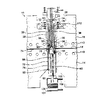
Referring first to Figure 1, a mold assembly in accordance with the
present invention is indicated generally by the reference 10. The mold
assembly 10 includes, in known manner, a first mold half 14 and a second
mold half 16. The mold halves 14, 16 define a mold cavity space 18.
It will be appreciated that, for convenience, the mold assembly 10 is
shown in a vertical position in Figure 1. However, the mold can be
oriented in any suitable way, which will often be governed by the particular
injection molding equipment used. Thus the mold could be arranged
horizontally. Also, either one or both of the mold halves, 14, 16 can be
movable, although in this embodiment the mold half 14 is movable.
At the top of the mold half 16 there is a substantial recess 26 which
continues into a bore extending through the mold half 16, the bore
comprising a first bore portion 28 of relatively wide diameter and a second
bore portion 30 of relatively small diameter.
A slidable mold injection nozzle 32 has a nozzle head portion 34
providing a shoulder that abuts against the mold plate 16. The nozzle
head 34 also includes an outer sleeve 35 that slidably engages the first
bore portion 28. Outside of the sleeve 35, there is an annular slot 36, and
a compression spring 37 acts between the nozzle head 34 and the mold
plate16.
The injection nozzle 32 further comprises a nozzle housing 38
having an axial nozzle melt channel 40 for feeding the molten resin into
the mold cavity space, the nozzle 32 further having a nozzle inlet portion
42.
A machine injection nozzle 44 abuts this nozzle inlet 42. The
spring 37 maintains the head portion 34 of the mold injection nozzle and
the machine injection nozzles 44 in sealed contact and in fluid
communication with one another, and has a spring rate and size such that,
contact between them is maintained without drool during the injection
process. The machine injection nozzle 44 and consequently the mold
CA 02269230 1999-04-19
18
injection nozzle 32 are moved in known manner by means not shown
between an injection position shown in Figure 1 and a post injection
position shown in Figure 2.
As shown in more detail in Figure 4a, the free end of the elongate
s nozzle housing 38 continues into a nozzle tip portion 50. The tip portion 50
comprises a gating portion 52, that cooperates with the plug 90 described
below, to define a mold gate 98.
The tip portion 50 further comprises an outer sliding surface 54. In
one embodiment, within the fixed mold half 16 and facing the mold cavity
to 18, there is a second cylindrical bore 56 that faces downwardly.
According to one aspect of this current invention, within this bore
56, there is a sleeve 58 made of a suitable thermal insulating material
(such as titanium or titanium alloys) defining an internal cylindrical bore
60,
as part of the second bore portion 30, along which the cylindrical surface
is of the nozzle tip 54 slides, and the shuttling plug 90 slides.
Turning now to Figure 1 for further details of the mold 10, a bore 72
extends through the movable mold half 14, and includes, adjacent the
mold cavity 18, a portion of enlarged diameter. The mold according to this
invention may be used to form "blank" discs with no pits that can be later
20 on bonded to an information carrier discs to form a certain type of DVD or
other type of molded disc. In this case the mold does not comprise a
stamper plate 74 and means to retain and eject the stamper plate. In a
preferred embodiment and in known manner, a stamper plate 74 known in
the art is mounted inside the cavity space located on the moveable mold
2s half 14 and is secured by a retention cylinder 76, which is fixed in
position.
The retention cylinder 76 defines an internal bore within which an
ejection cylinder 78 is slidably mounted. An actuation unit (not shown) is
provided for driving the ejection cylinder 78 upwardly to eject a molded
disc in known manner.
~o The ejection cylinder 78 defines an internal bore 80 having a first
bore section 82 of relatively small diameter and a second bore section 84
of relatively large diameter. In one embodiment, a fluid drive unit 86 is
AMENDED SHEET
CA 02269230 1999-04-19 ~~_ :~~
. " . , .,
l9
connected to a plunger 88 for displacing a shuttling plug 90, which is an
innovative and very accurate component of the mold design in accordance
with the present invention. The plunger 88 simply abuts the plug 90 and is
not secured to the plug 90. As further shown schematically in Fig. 1 a) in
s some detail, the actuation of the plunger 88 can be effected by other
constructions, for example in a more accurate and secure manner by a
wedge mechanism 105 actuated by fluid 103 or other suitable means. The
movement of the wedge 105 is limited by a movable pin (spring (111)-
biased) 107 operated by fluid actuating means 109 during the injection
io step. Means not shown are used to keep the plunger 88 in permanent
contact with the wedge.
During the sealing process of the nozzle by the shuttling plug 90,
the wedge is further moved by passing the pin 107 up to a second stop pin
101 that is stationary. Means not shown, but known in the art may be used
Is to monitor from outside the mold the position of the wedge or/and of the
plunger and the position of the mold injection nozzle in order to determine
exactly the thickness of the gate. Functions of the molding conditions and
the thickness and the position of the gate can be adjusted without
interrupting the molding process with high accuracy.
2o SHUTTLING PLUG DESIGN
The shuttling plug 90 is initially located in the movable mold half
and serves several critical functions, as detailed below, namely to form in
conjunction with the nozzle tip a circular mold gate with no mechanical
obstructions, to guide the incoming tubular flow of molten material and
2s change it from a tubular flow into a radial flow filling the mold cavity
space,
to act at least partially as a core and thus form at least partially a through
hole in the of a disc and finally to seal off the mold gate through its move
into the stationary mold half, at least partially, until it makes a seal
contact
with the nozzle tip portion of the movable mold injection nozzle.
~o According to the current invention, the position of the circular gate
relative to the mold cavity space and its thickness can vary, as dictated by
the actual injection molding parameters and by the specific material to be
AMENDED SHEET
CA 02269230 1999-04-19
.~ .. .,
molded. Details of one variant of the plug 90 are shown in Figures 4a and
4b. As shown in Figures 4a and 4b, the plug 90 has a sliding and coring
body portion 92, a passive portion 91 facing plunger 88 and a gating
portion 94 facing the injection nozzle tip. In one preferred embodiment,
s plug 90 is formed as a body of revolution and the upper gating portion 94
comprises an apex 96. This apex engages the incoming tubular flow of
resin before it reaches the nozzle tip portion to facilitate the smooth
conversion from a tubular flow to a radial flow while having for a short
distance an intermediate and transitional annular flow between the tubular
to and radial flow patterns.
As shown in Figures 1 and 4a, in cross section, upper portion 94 of
plug 90 comprises in one embodiment a curved surface of revolution. This
curved surface is shaped to cooperate with the gating portion 53 of the
nozzle tip portion 50 so that together they form a melt channel terminating
is with the circular mold gate 98 of a thickness T or h2 as it is also
referred to
later in this description.
Upper portion 94 can actually have various shapes depending on
the specific molding application as shown in more detail in Figs. 5a to 5j.
The shape of this surface is always selected based on computerized melt
2o flow analysis in such a manner as to serve several functions: e.g., seal
the
gate in conjunction with the nozzle tip, transform the incoming tubular flow
into an annular flow and finally converting it into a radial flow entering the
cavity space through a circular gate with no turbulence.
In most instances it is desirable to achieve a minimum contact area
2s between the nozzle tip gating portion 53 and the shuttling plug gating
portion 94, and preferably that area is reduced to a circle. This allows for
improved sealing and also minimum contact between the two abutting
surfaces that contribute to rapid disengagement of the plug and the nozzle
prior to each injection step. Also by having minimum contact, substantially
~o no material is left on either the plug or the nozzle after each injection
step.
As shown in more detail in Fig. 4b, the angular difference between
the gating surfaces of the plug and nozzle tip provides the benefit that
AMENDED SHEET
CA 02269230 1999-04-19
21
substantially no molding material is returned into the melt channel of the
nozzle by the movement of the plug to seal the gate. This is a critical
requirement especially when molding information carrier substrates used
with light based readers. As further shown in Fig. 4a the nozzle tip and the
s upper portion of the plug 94 form a "virtual" and circular mold gate 98 that
has no mechanical obstruction. This is a unique feature not contemplated
by the prior art whereby the resin flows in a tubular flow completely
unobstructed through an injection nozzle located into a first mold half up to
the nozzle tip where it is converted first into an annular flow and then into
a
to completely unobstructed radial flow that is further injected through a
circular mold gate into a cavity space and wherein the flow of resin is
interrupted after filling the cavity space by a valve gating means located
outside the nozzle melt channel that is movable against the nozzle tip and
wherein the nozzle tip and the valve gating means form said unobstructed
is circular mold gate. Substantially no molding material is removed by the
displacement of the shuttling plug inside the cavity space during its
movement towards the nozzle tip to shut-off and seal the gate after the
injection step.
The nozzle housing 38, in the advanced or molding position, is
20 located so that the tip portion 50 is positioned a distance h1 below the
top
of the mold cavity 18. The gate passage 98, at its outlet, is formed
between tip portion 50 and upper gating portion 94 that is positioned at a
height h2 in the mold cavity space. A unique feature of the present
invention is that both the position and the thickness of the gate 95 within
2s the cavity can be adjusted before or during the molding process by
independently displacing nozzle 38 and/or plug 99 to vary height h1 andlor
height h2.
As shown in Figure 4b, the plug 90 can be brought into abutment
with the tip surface 52, to close off the tip portion 50. Due to the tapered
~o profile of the mold gate passage 98, sealing occurs at the outer periphery
of the head surface 94 and the tip portion 50, along second sealing
surfaces generally indicated at 100. These second sealing surfaces 100
AMENDED SHEE1
CA 02269230 1999-04-19 -- w
21a
can either be essentially a nominal line contact, or the surfaces can be
configured to provide sealing surfaces having a desired radially extent, i.e.
being generally annular.
As detailed below, the plug 90 is displaced by the plunger 88 driven
s by the fluid drive unit 86. The drive unit 86 comprises a cylinder defining
a
AMENDED SHEET
CA 02269230 1999-04-19
WO 98/19846 PCT/CA97/00827
22
first chamber 102 and a second chamber 104 separated by a piston 106,
which is connected to the plunger 88. Appropriate connections 108 are
provided for connection to a fluid supply, for operation of the piston 106 in
known manner. The piston 106 works in conjunction with the movement of
the machine nozzle 44 and has two functions. One function is to move the
plug 90, which shuttles back and forth, and the other function is to form an
adjustable stop, i.e. to oppose the molding pressure to the molten resin
and the resistance of the actual spring 48 when the plug 90 travels within
the guide bushing 58. As shown in Figure 1 a, the same function can be
achieved by using a wedge design.
The mold assembly 10 can be heated and cooled in known
manner. Thus, for this purpose, the fixed and movable mold halves 14, 16
are provided with cooling channels 110. Similarly, an elongate cylindrical
heating element 112 is provided around the elongate nozzle housing 38,
and other heaters can be provided, to maintain resin within the mold
injection nozzle 32 molten.
In use, the mold assembly 10 is in the closed position at the start
of a cycle as shown in Figure 1, with the mold injection nozzle 32 in the
molding position, namely with the tip portion 50 adjacent the cavity 18, as
maintained by the mechanical pressure of the machine nozzle applied to
the mold nozzle. The molten resin is injected under pressure from the
machine injection nozzle 44, through the nozzle channel 40 and the mold
gate passage 98 into the mold cavity 18. It can be noted that the
combination of the various channels provides a smooth, continuous
channel, which has no abrupt changes in section and which shows no
obstructions in the channel. This design avoids problems due to varying
shear history within the material and the generation of weld lines which
can result in birefringence. The circular mold gate passage 98 can be
such as to create a back pressure and reduce the velocity of the molten
resin filling the mold cavity 18.
As shown in Figure 4a, during filling of the mold cavity 4a, the
piston 106 with the plunger 88 can be operated to maintain the plug 90 in
CA 02269230 1999-04-19
WO 98/19846 PCT/CA97/00827
23
a desired location, so as to control the width or height h2 of the mold gate
passage 98. Thus, the mold gate passage 98 can be varied in section,
depending on variations in various parameters. For example, the viscosity
of the resin will vary with temperature and the pressure which resin is
delivered will vary. The width of the mold gate passage 98 can be varied
to ensure a uniform.and desired filling rate of the mold cavity 18. Again, if
the mold cavity 18 is filled too quickly, the problems with weld lines and
birefringence can occur. As shown in Figure 1 a, the same function can be
achieved by using a wedge design.
As shown in Figure 4a, the width of the mold gate passage 98 is
measured by the axially spacing h2 at the outer circumferential periphery
of the mold gate passage 98. At all times, the heating element 112 is
operated to maintain resin within the nozzle channel 40 molten.
After injection of molten resin is stopped by switching off the
injection molding machine, the plug 90 is displaced by the piston 106 and
plunger 88. The plug 90 travels through the distance h2, to complete the
formation of a central hole 116 in the disc, indicated at 114, this hole
having a diameter corresponding to the diameter of the cylindrical body
portion 92 of the plug 90. The plug 90 then abuts and seals off the tip
surface 52, as shown in Figure 4b.
The plug 90 is continuously displaced by the piston 106 until it has
been displaced a further distance L (see Figures 2,3 and 4b).
Simultaneously, the mold injection nozzle 32 and machine injection nozzle
44 are displaced backwards by the same distance L, to allow the plug to
enter fully over its full length within the guiding sleeve or bushing 58, as
shown in Figure 2. The injection nozzle 32 has then reached the second
position, in which the tip portion 50 is spaced from the mold cavity 18.
Aiso, the machine injection nozzle is retracted, so it is not urging the mold
injection nozzle into the molding position.
The spring 37 ensures that the mold and machine injection nozzles
32, 44 are always in contact with one another. The mold 10 is cooled to
solidify the disc 114. During this time, the outlet or tip portion 50 is
CA 02269230 1999-04-19
WO 98/19846 PCT/CA97/00827
24
maintained closed. This has a number of advantages. Firstly, the mold
injection nozzle 32, which is maintained hot is displaced away from the
mold cavity 18, where cooling of the disc continues. This ensures that
resin at the tip of the nozzle can be maintained hot ready for the next
cycle, without being affected by further cooling of the disc just formed.
Throughout this motion the good seal created between the plug 90 and tip
surface 52 is maintained. This prevents contamination of the next shot of
material into the mold cavity.
With the disc 114 fully solidified, the mold is then opened as shown
in Figure 3. The plunger 88 is then retracted to clear the hole 116 in the
disc 114. As the machine injection nozzle 44 has been retracted, the mold
injection nozzle 32 is maintained in the second position by the spring 37.
A significant feature of this opening step is that the plug 90 cannot drop
since it is kept inside the guiding sleeve 58 by frictional forces and also
due to the gluing effect exercised by the thin film of molten resin in the
tapered area between the plug and the nozzle. In another embodiment,
shown in Figure 12 and described below, some mechanical means is used
to securely maintain the plug inside the guiding sleeve 58. As the resin
supply is shut off, the plug 90 cannot drop since there is no path to permit
air to break the seal between the plug 90 and the resin within the conduit
40. The mold is open by a distance D, greater than the distance L, to
provide room for a part removal robot. With the mold open, the disc 114
can be removed by a robot arm or the like in known manner.
The mold halves 14, 16 are then closed again. The piston 106 is
again controlled to form a mold gate passage 98 with a desired gate
height h2. Another disc 114 can then be molded as above.
An important aspect of the present invention is the configuration of
the tip portion 50 and the head surface 94 of the plug 90. As shown in
other figures, the head surface 94 can have a variety of configurations,
and correspondingly, the tip surface 52 can have a number of different
configurations. Generally, these include first surfaces that define the mold
gate, and second sealing surfaces for abutting one another to close the
CA 02269230 1999-04-19
WO 98/19846 PCT/CA97/00827
gate. The sealing surfaces provide either a nominal line contact or an
annular sealing surface, which preferably extends radially inwards from
the outer peripheries of the tip portion 50 and the plug 90.
Referring first to Figure 5a, there is shown a combination of a plug
90a and tip surface 52a, where the plug 90a has a head portion 94a that
shows concave surfaces, in section as the earlier embodiment. Here, the
head portion has a height that is substantially greater than the diameter of
the shuttling plug 90a, so as to extend a long way into the channel 40.
This is done so as to provide a particularly smooth transition from the axial
flow in the channel 40 to the radial flow from the gate passage 98.
Figure 5b shows a version of the plug indicated at 90b with a tip
surface 52b, which have complementary concave and convex surfaces.
Here, the plug 90b is shown with a height H1, a diameter D1 and a head
portion 94b having a height K1 and a radius for the concave portion, in
section, of R1. The various dimensions H1, D1, K1 and R1 would be
related as desired. Thus, K1 could either be less than or greater than D1
as required; it will be appreciated that in the Figure 5a version, the
dimension K1 can be a significant multiple of the dimension D1.
A shuttling plug 90c, in Figure 5c has a generally convex or domed
shape with a head portion having a height K2. This cooperates with a tip
surface 52c which correspondingly shows convex surfaces. These
surfaces are configured to provide a nominal, sealing line, in the closed
position, at the periphery of plug 90c and tip surface 52c.
Figure 5d shows a further variant, where a shuttling plug 90d again
has a domed or rounded head surface. Here, this cooperates with a tip
surface 52d having a complementary concave, curved surface, so that
sealing is achieved over a substantial area.
A plug 90e in Figure 5e has a concave, curved head surface or
portion indicated at 94e. Here, this cooperates with an tip surface 52e
showing concave surfaces. This has the advantage of producing a large
internal volume adjacent the gate, which may reduce shear effects
immediately preceding the gate and be desirable for some uses.
CA 02269230 1999-04-19
WO 98/19846 PCT/CA97/00827
26
Figure 5f shows a combination of a shuttling plug 90f showing a
configuration similar to Figure 4a, with concave surfaces, and a tip surface
52f showing a rounded, concave end surface. These surfaces would
again be configured to provide sealing at the radially outward peripheries
thereof.
In Figure 5g, a plain, cylindrical plug 90g has a height or axially
length H2 and a diameter D2, which would be related as desired. A tip
surface 52g shows convex surfaces, and somewhat like Figure 5e, this
would provide a large flow area immediately adjacent the gate.
Figure 5h shows a shuttling plug 90h, generally similar to plug 90g,
in cooperation with a tip surface 52h generally similar to the tip surface
52f, i.e. with a curved, concave lower surface. Again, this would provide a
sealing at the radial outer periphery.
Complementary conical profiles are shown in Figure 5i. Here, a
shuttling plug 90i has a generally conical head surface 94i with a height
K3. Correspondingly, a tip surface 52i is a complementary conical surtace
to provide sealing over the full extent of the surface.
Figure 5j shows a variation of this conical arrangement. Here, a
shuttling plug 90j again has a conical surface, but with a lower height. The
tip surface 52j corresponds to the tip surface 52i, so that a gate passage is
provided that decreases in height in the radially outward direction, and
sealing is provided at the outer peripheries of the plug 90j and tip surface
52j.
in Figure 5k, a shuttling plug 90k is generally cylindrical, as in
Figure 5g, and is shown in conjunction with a tip surface 52k showing a
conical surface, again as in Figures 5i and 5j.
Finally, in Figure 51, there is shown a simple cylindrical plug 901, in
conjunction with a tip surface 521 showing a planar end surface, so that an
outlet passage of uniform height would be formed, as shown.
Thus, it will be appreciated that a variety of shapes can be provided
for the plug and the tip portion of the nozzle. Each of the plug and the
nozzle can have any of a planar surface; a conical surface; a variety of
CA 02269230 1999-04-19
WO 98/19846 PCT/CA9710(1827
27
convex surtaces; and a variety of concave surfaces. Further, the surfaces
of each can show combinations of concave portions, convex portions,
planar portions and other profiles. The configuration could be such as to
provide either a nominal line contact around the edge or at some other
location, or sealing over a substantial radial extent. In all cases, the
location of the tip portion determined by the dimension H1 in Figure 4a,
can be varied, as can the height of the outlet passage 98, i.e., the
dimension h2.
To optimize the performance of the plug, it can be provided with
means to heat the plug, and also can be formed from materials which
provide insulating and/or conductive capabilities. For this purpose, the
plug can be made from two or more separate parts.
The plug can also be made using a high wear resistance material,
such as tungsten carbide or other powder injection molded material. The
plug may be replaced by manual or automatic means after a certain
number of molding cycles. In a preferred embodiment, the plug can be
removed using the same robot means (not shown} that may be used to
change the stamper plate.
Thus, with reference to Figure 6, a plug 140 comprises a body part
142 forming most of the cylindrical body and a head part 144 forming the
head and part of the cylindrical body. The body part 142 could be formed
from an insulating material, such as titanium or a ceramic so as to
maintain it cooler than the head portion, since it is remote from the molten
resin. On the other hand, the head part 144, forming the head portion can
be formed from a highly conductive material, such as copper-beryllium, so
as to maintain a uniform, high temperature in the resin at all times. This
should maintain a uniform temperature in the resin as it flows into the
cavities. Also, when flow of resin is interrupted but a disc is cooling and
the mold is opened etc., this helps to ensure that resin at the outer edge of
the mold gate passage 98 is maintained at a temperature close to that of
the resin in the nozzle channel 40, to maintain uniform properties in the
resin.
CA 02269230 1999-04-19
WO 98/19846 PCT/CA97/00827
28
Additionally or as well, appropriate coatings can be provided to
enhance these effects. Thus, an insulating layer 146 can be provided
around the cylindrical body portion 92 and a conductive layer 148 can be
provided on the top of the head portion.
With reference to Figure 7, a further plug 150 is shown. This plug
150 comprises a central part 152 defining an internal recess 154 and also
the surfaces of the head portion indicated at 156. The cylindrical body
portion 92 is defined by an outer part 158. The central and outer parts
152, 158 can be formed, respectively, from conductive and insulating
materials, as detailed above.
Here, a heating element 160 is placed within the recess 154. It is
provided with contact pins 162 and a thermocouple 164 is also mounted
within the recess 154 and correspondingly has its own contact pins 166.
Thus, when the plug 150 is in the retracted position of Figure 1, the
contact pins 162, 166 will contact corresponding pins. The abutting pairs
of contact pins are provided with sufficient resiliency to accommodate the
movement of the plug 150 as required to vary the gate height h. This
ensures that the heating element 160 can be continuously operated during
filling of the cavity 18.
To applicant's knowledge, this combination of materials, provision
of a heating element and a thermocouple for temperature control are
wholly new in this art. They are selected to ensure that the resin is
delivered to the cavity uniformly, and at a constant temperature, and with
minimum shear disturbance. This will all contribute to the formation of an
accurate and stress-free hole in the of the disc or other molded article.
For some applications, it may be necessary for the hole formed in
the of the article to have a shape other than a circular shape. For
example, in the case of a gear, it may be desirable to form a hole with
various splines for torque transfer to or from the gear. Such an
arrangement is shown in Figures 8, 9a and 9b. In Figure 8, a disc or other
circular article 170 has a hole 172 which includes four approximately
square extensions 174. For this purpose a plug 176, having an
CA 02269230 1999-04-19
WO 98/19846 PCTICA97100827
29
appropriate profile is provided with four square protrusions 178. In use,
the plug 176 would slide into the sleeve or bushing 58. However, the
protrusions 178 extend beyond the diameter of the sleeve 58 and would
be located in the mold cavity during the molding process, so as to form the
extensions 178 of the hole 172.
Figure 10 shows another variation. Here, a gear 180 has a single
slot 182 for a key or spline to secure the gear to a shaft. In Figure 11,
there is shown a gear 184 with numerous splines or threads 186 again for
attachment to a shaft.
With reference to Figure 12, there is shown a mechanism for
assisting in retaining the plug in the first or movable mold half 16. Here,
the plug, indicated at 90a, is provided with an annular channel or waist
portion 188. Spring-biased retaining pins 190 engage the plug 90a in the
second position, i.e. as in Figure 3, to assist in holding the plug 90a in
this
position when the mold is opened.
According to the current invention, the shuttling plug 90 performs
the additional mold core and the gating functions without displacing molten
material back into the cavity space and the mold injection nozzle. Also, the
mold injection nozzle is movable towards the machine injection nozzle to
allow the shuttling plug to remain, at least partially inside the cavity
space,
and to allow for changing of the mold gate thickness and its position.
According to the current invention, the shuttling plug does not travel inside
the melt channel of the mold injection nozzle, as taught by Wilson ' 464,
but inside the bore which guide the movement of the mold injection
nozzle.
It will be apparent to the reader that various changes and
modifications may be made to the constructions of the present invention
without departing from the spirit and scope of the invention as set out in
the subsequent claims. All such changes are encompassed by the claims.