Note: Descriptions are shown in the official language in which they were submitted.
CA 02269279 2001-05-03
DOOR SYSTEM FOR TRANSIT VEHICLE
FIELD OF THE INVENTION
The present invention relates, in general, to an operator
for a passenger transit type vehicle door system and, more
particularly, the present invention relates to an operator for
biparting slide glide and swing type door systems for passenger
transit vehicles.
BACKGROUND OF THE INVENTION
The design of passenger transit vehicle doors is crucial
for the safety of the travelling public. As is well known in
the transit industry, these doors must function in a relatively
hostile environment which at least include heavy usage,
temperature extremes, vibration and acceleration loads. They
must open and close quickly and they must meet conflicting
requirements such as being securely closed when they are in the
closed position and yet they must be capable of being opened
manually to provide emergency egress of passengers.
One known prior art system is described in United States
Patent number 5,332,279, which is entitled POWER DOOR OPERATOR
FOR MULTI-PASSENGER MASS TRANSIT VEHICLES.
The operator described in the referenced patent has an
electrical motor attached to a transmission. The transmission
has an output power shaft which engages drive arms connected to
rods which open and close the doors. A spring loaded clutch
1
CA 02269279 1999-04-16
plate includes a pair of pins engaging a collar attached to the
drive arms to maintain the drive arms in engagement with the
output power shaft of the transmission.
To provide emergency egress when the doors are closed, a
plunger pushes the clutch plate to disengage the drive arms
from the transmission output power shaft so that the doors can
be opened. Difficulties have been experienced with this prior
art design because the pin and collar combination tends to bind
if it is not perfectly aligned. Additionally, when the doors
are opened and closed, the pins slide in a groove in the collar
and experience excessive wear. This is because the pins
continually exert a force on the collar to bias the drive arms
into engagement with the output power shaft of the
transmission.
SUMMARY OF THE INVENTION
In a first embodiment, the present invention provides an
operator for a mass transit vehicle door system having a pair
of biparting doors. It includes a base for attachment to the
mass transit vehicle and a motive power source. It also
includes a transmission connected to receive motive power from
the motive power source. Such transmission includes a
transmission output power shaft. Either the motive power
source or the transmission is attached to the base. The
operator further includes a teeter plate having a shaft
engaging portion for engaging the shaft. The shaft has a
teeter plate engaging portion for engaging the operator teeter
2
CA 02269279 1999-04-16
plate. A thrust bearing is in mechanical contact with a hub
portion of the teeter plate and a spring is in mechanical
contact with the thrust bearing to exert a first axial thrust
thereon. Such thrust bearing communicating the first axial
thrust to the teeter plate so that the shaft engaging portion
of the teeter plate engages the teeter plate engaging portion
of the shaft. The operator further includes a release member
having mechanical contact with the hub portion of the teeter
plate for exerting a second axial thrust on the teeter plate.
This second axial thrust being opposed to the first axial
thrust so that the teeter plate may be disengaged from the
shaft by the release member. A pair of drive rod pivots are
attached to the teeter plate. The pair of drive rod pivots are
connected to a pair of drive rods for opening and closing the
pair of biparting doors.
In a second embodiment, the present invention provides
a biparting swing door system for a mass transit vehicle. Such
biparting swing door system includes an operator which has a
base for attachment to the mass transit vehicle and a motive
power source. The biparting swing door system, also, includes
a transmission which is connected to receive motive power from
the motive power source. Such transmission having a
transmission output power shaft. Either the motive power
source or the transmission is attached to the base. The
operator has a teeter plate having a shaft engaging portion for
engaging the shaft and the shaft has a teeter plate engaging
3
CA 02269279 1999-04-16
portion for engaging the teeter plate. A thrust bearing is in
mechanical contact with a hub portion of the teeter plate and
a spring is in mechanical contact with the thrust bearing to
exert a first axial thrust thereon. Such thrust bearing
communicating the first axial thrust to the teeter plate so
that the shaft engaging portion of the teeter plate engages the
teeter plate engaging portion of the shaft. Further, the
operator has a release member having mechanical contact with
the hub portion of the teeter plate for exerting a second axial
thrust on the teeter plate. The second axial thrust being
opposed to the first axial thrust so that the teeter plate may
be disengaged from the shaft by the release member. A pair of
drive rod pivots are attached to the teeter plate and a pair of
drive rods are attached to the drive rod pivots. The system
includes a pair of biparting swing doors and the drive rods are
attached to door drive pivots connected to the biparting swing
doors to move the doors between open and closed positions.
In a third embodiment, the instant invention provides a
biparting slide glide door system for a mass transit vehicle.
This system includes an operator which has a base for
attachment to the mass transit vehicle and a motive power
source. It also has a transmission connected to receive motive
power from the motive power source. The transmission includes
a transmission output power shaft. Either the motive power
source or the transmission is attached to the base. The
operator further includes a teeter plate having a shaft
4
CA 02269279 1999-04-16
engaging portion for engaging the shaft. The shaft has a
teeter plate engaging portion for engaging the teeter plate.
A thrust bearing is in mechanical contact with a hub portion of
the teeter plate and a spring is in mechanical contact with the
thrust bearing to exert a first axial thrust thereon. Such
thrust bearing communicating the first axial thrust to the
teeter plate so that the shaft engaging portion of the teeter
plate engages the teeter plate engaging portion of the shaft.
The operator further includes a release member having
mechanical contact with the hub portion of the teeter plate for
exerting a second axial thrust on the teeter plate. This
second axial thrust being opposed to the first axial thrust so
that the teeter plate may be disengaged from the shaft by the
release member. A pair of drive rod pivots are attached to the
teeter plate and a pair of drive rods are attached to the drive
rod pivots. The system has a pair of biparting slide glide
door panels and the drive rods are attached to door drive
pivots connected to the biparting slide glide doors to move the
doors between open and closed positions.
OBJECTS OF THE INVENTION
It is, therefore, one of the primary objects of the
present invention to provide an operator for biparting
passenger transit vehicle doors which may be disengaged so that
the doors may be opened.
CA 02269279 1999-04-16
Another object of the present invention is to provide a
transit vehicle door operator having a teeter plate which
undergoes less wear than prior art designs.
Still another object of the present invention is to
provide a biasing means for a teeter plate in a transit vehicle
door system which uses a thrust bearing to reduce wear.
Yet another object of the present invention is to provide
a biasing means for a teeter plate in a transit vehicle door
system which reduces binding.
A further object of the present invention is to provide a
biasing means for a teeter plate in a transit vehicle door
system which is highly reliable.
It is an additional object of the present invention to
provide a biasing force for a teeter plate in a transit vehicle
door system which can be manually overcome to provide emergency
egress of passengers.
Still yet another object of the present invention is to
provide a biasing means for a teeter plate in a transit vehicle
door system which can readily be retrof fitted into the prior art
system.
An additional object of the present invention is to
provide a biparting transit vehicle door system having a stop
to control compression of the door seals when the doors are
closed.
Another object of the present invention is to provide a
biparting transit vehicle door system having an adjustable stop
6
CA 02269279 1999-04-16
to control compression of the door seals when the doors are
closed.
Also, an object of the present invention is to provide a
stop to precisely limit the closure of the doors to prevent
locking of the drive mechanism.
In addition to the various objects and advantages of the
present invention which have been generally described above,
there will be various other objects and advantages of the
invention that will become more readily apparent to those
persons who are skilled in the relevant art from the following
more detailed description of the invention, particularly, when
the detailed description is taken in conjunction with the
attached drawing figures and with the appended claims.
BRIEF DESCRIPTION OF THE DRAWINGS
Figure 1 is a front elevation view of a biparting swing
door system for a passenger transit vehicle according to the
present invention.
Figure 2 is a top view of a biparting swing door system
for a passenger transit vehicle according to the present
invention.
Figure 3 is a front elevation view of a transit vehicle
door actuator according to the present invention.
Figure 4A is a top view of the transit vehicle door
actuator, illustrated in Figure 3, with the release member in
normal and release positions.
7
CA 02269279 1999-04-16
Figure 4B is a sectional detail of a thrust bearing used
to bias the teeter plate into engagement with the output power
shaf t .
Figure 5A is a side elevation view of the teeter plate.
Figure 5B is a sectional detail of the hub of the teeter
plate showing a circumferential groove and a recess for the
thrust bearing.
Figure 6 is a front elevation view of the release member.
Figure 7A is a front elevation view of the teeter plate.
Figure 7B is a front elevation view of the end of the
transmission output power shaft which shows the teeter plate
engaging portion.
Figure 8 is a front elevation view of a biparting slide
glide passenger transit vehicle door system according to this
invention.
Figure 9 is a top view of the biparting slide glide
passenger transit vehicle door system, illustrated in Figure 8,
according to this invention.
BRIEF DESCRIPTION OF THE PRESENTLY
PREFERRED AND VARIOUS ALTERNATIVE
EMBODIMENTS OF THE INVENTION
Prior to proceeding to the much more detailed description
of the present invention, it should be noted that identical
components which have identical functions have been identified
with identical reference numerals throughout the several views
illustrated in the drawing figures for the sake of clarity and
understanding of the invention.
8
CA 02269279 1999-04-16
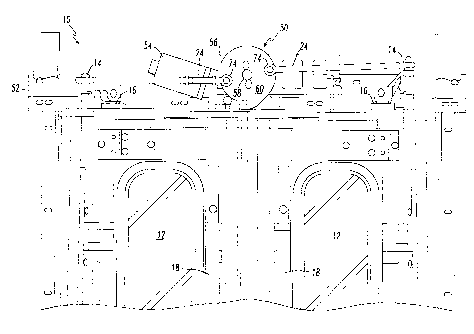
Reference is now made, more particularly, to Figures 1 and
2. Illustrated therein is a biparting passenger transit
vehicle swing door system, generally designated 10, according
to one presently preferred embodiment of the invention.
The swing door system 10 includes an operator, generally
designated 50. Operator 50 includes a base 52 and a motive
power source 54 which drives a transmission 56. Additional
detail with respect to the operator 50 is provided in Figures
3, 4A, 4B, 5A, 5B, 6, 7A and 7B.
It is presently preferred that the transmission 56 be
attached to base 52. The transmission 56 has an output power
shaft 58 which engages a teeter plate 60. A pair of drive rods
24 are attached to drive rod pivots 74 disposed on such teeter
plate 60. Such drive rods 24 are attached to door drive pivots
14 to open and close the doors 12. Doors 12 are shown closed
in Figures 1 and 2, and their open positions are shown in
phantom. Touch bars 18, which may be used by a passenger to
open doors 12 when the vehicle (not shown} is stopped, are
provided. The doors 12 are pivoted about door pivots 16 and,
preferably, such doors 12 are provided with door seals 20 and
22.
Illustrated in Figures 8 and 9 is a presently preferred
biparting slide glide door system, generally designated 30,
according to an alternative embodiment of the invention.
The presently preferred operator 50 may be used for
various biparting door systems, including the swing door system
9
CA 02269279 1999-04-16
having biparting swing doors 12 or such slide glide door
system 30 having biparting slide glide doors 32. Operator 50
has the base 52 for attachment to the passenger transit vehicle
(not shown) and a motive power source 54.
In the presently preferred embodiment, motive power source
54 is an electric motor. In this embodiment of the invention,
the operator 50 also includes a transmission 56 connected to
the motive power source 54 in order to receive motive power
therefrom. The transmission 56 having a transmission output
power shaft 58. It is presently preferred that the
transmission 56 not be back drivable so that the transmission
56 acts as a lock to prevent inadvertent opening of the doors
12 or doors 32 when they are closed. Either the motive power
source 54 or the transmission 56 is attached to the base 52.
Operator 50 includes a teeter plate 60 having a shaft
engaging portion 100 for engaging the shaft 58 and the shaft 58
includes a teeter plate engaging portion 110 for engaging the
teeter plate 60. In the presently preferred embodiment shown,
the teeter plate engaging portion 110 of the shaft 58 includes
at least one substantially radially oriented member 82,
preferably a shaft. Also, it is presently preferred that the
shaft engaging portion 100 of the teeter plate 60 include a
central opening 78 and two slots 80 which are oriented
substantially radially. Slots 80 are for receiving the
radially oriented members) 82 to provide a rotary connection
between teeter plate 60 and shaft 58. Teeter plate 60 slides
CA 02269279 1999-04-16
on the shaft 58 to engage and disengage radially oriented
members) 82 with slot 80.
A thrust bearing 66 is in mechanical contact with a hub
portion 68 of the teeter plate 60 and a spring 70 is in
mechanical contact with the thrust bearing 66 to exert a first
axial thrust on thrust bearing 66. The thrust bearing 66
communicates the first axial thrust to the teeter plate 60 so
that the shaft engaging portion 100 of the teeter plate 60
engages the teeter plate engaging portion 110 of the shaft 58.
It is presently preferred that the hub portion 68 of such
teeter plate 60 have an annular recess 67 for receiving such
thrust bearing 66. Preferably, the spring 70 is a coil spring
disposed concentric with the shaft 58 and with the shaft 58
disposed inside the spring 70.
The operator 50 includes a release member 72 disposed in
mechanical contact with the hub portion 68 of the teeter plate
60 for exerting a second axial thrust on the teeter plate 60.
Such second axial thrust being opposed to the first axial
thrust so that the teeter plate 60 may be disengaged from the
shaft 58 by such release member 72.
In the presently preferred embodiment, such release member
72 is a lever pivoted at release lever pivot 84 and includes a
teeter plate engaging portion 85. Hub portion 68 has a release
lever engaging portion 86 which preferably is a circumferential
groove formed in hub portion 68. It is also preferred that
such release member 72 have a pair of pins 88 for engaging with
11
CA 02269279 1999-04-16
circumferential groove 86. Additionally, release member 72
preferably has a motion receiving portion 90 which preferably
is attached to a plunger 92 having a knob 94 to be manually
activated.
When the doors 12 or the doors 32 are closed and held in
the closed position by the transmission 56, a person may open
these doors by pressing knob 94 to move the plunger 92 to
rotate such release member 72 which moves hub portion 68 and
hence such teeter plate 60 in order to disengage such teeter
plate 60 from shaft 58. When this is done, teeter plate 60 is
free to rotate about shaft 58 and the doors 12 or 32 may be
opened.
There are a pair of drive rod pivots 74 attached to the
teeter plate 60. Such pair of drive rod pivots 74 are
connected to a pair of drive rods 24 or 48 for opening and
closing the pair of biparting doors 12 or 32. It has been
found to be desirable to attach braces 75 to the drive rod
pivots 74, as shown in Figures 3 and 5A.
It is presently preferred that the teeter plate 60 have a
teeter plate stop 96 which provides precise control of the
closed positions of doors 12 or 32 and, also, the compression
of the door seals 20 and 22 or 44 and 46. If a control system
failure permitted the doors to be closed beyond the normal
position, by excessive compression of the seals, the door drive
pivots 14 or 34 would move to a locked position in which the
doors could not be opened.
12
CA 02269279 1999-04-16
In the preferred embodiment shown, teeter plate stop 96 is
a step in the perimeter 97 of teeter plate 60. Teeter plate
stop 96 is for engagement with base stop 98. Preferably, base
stop 98 has a position which is adjustable so that the
compression of the door seals 20 and 22 or 44 and 46 may be
adjusted to a desired level. In the presently preferred
embodiment, drive rod pivots 74 are located approximately at
diametrically opposed positions as shown, for example, in
Figure 3.
Figures 8 and 9 show a slide glide door system 30
according to the invention. Operator 50 has teeter plate 60
which moves drive rods 48 which are connected to door drive
pivots 34. Movement of such drive rods 48 causes rotation of
the door drive pivots 34 which rotate outer door suspensions 42
which are attached to the doors 32. Doors 32 are also
suspended by inner door suspensions 38 which roll in tracks 40.
Figure 9 shows the doors 32 in a closed position in which the
door seal 44 engages door seal 46. This figure also shows, in
phantom, the doors 32 in the open position. J-arms 31 are also
attached to doors 32 to support doors 32. Such J-arms 31 are
attached to door pivots 36 and follow conventional practice in
the art of slide glide doors.
While a presently preferred and various additional
alternative embodiments of the instant invention have been
described in detail above in accordance with the patent
statutes, it should be recognized that various other
13
CA 02269279 1999-04-16
modifications and adaptations of the invention may be made by
those persons who are skilled in the relevant art without
departing from either the spirit of the invention or the scope
of the appended claims.
14