Note: Descriptions are shown in the official language in which they were submitted.
CA 02269303 1999-04-19
. 'Y r
JUNCTION BOX COVER
Field of the Invention
In general, the present invention relates to flooring covers. And, in
particular, the
present invention relates to a junction box cover for releasably installing in
an access port
of a junction box disposed under a floor.
Background
Typical junction box covers, which are primarily used in the floors of casinos
and
financial institutions for allowing access to underfloor junction boxes, are
undesirable for
the following reasons. The covers are difficult to install because they
require a number
of screws to be inserted through the top of the cover and into the junction
box.
Moreover, because the screws are accessible from the top of the cover, they
can be
undesirably loosened by individuals walking, or carts rolling, over the cover.
It is also
possible that unauthorized individuals could gain access to the junction box
by loosening
the screws. It is also common for installers to misplace or loose the screws,
thereby
allowing easy access to the junction box.
These covers are also not adjustable to accommodate various thicknesses of
flooring material, such as carpet, rubber mat, linoleum, or tile. Typical
covers also
consist of a relatively thin "pizza pan" type design that includes a
peripheral flange that
abuts the surrounding flooring material. When a heavy apparatus, such as a
cart of coins,
2
CA 02269303 1999-04-19
is rolled over one of these covers, the flange is bent into the flooring
material, damaging
it and further making the cover more difficult to remove. Therefore, this non-
sturdy
design, which easily deforms, is also unacceptable.
Summary of the Invention
The present invention eliminates the above difficulties and disadvantages by
providing a junction box cover for an access port that is disposed in a
junction box
adapted to be received at least partially within a floor having a flooring
material laid
thereon. The junction box cover includes a ring that has a lower surface and a
plurality
of threaded bosses extending downward therefrom. The access port has an outer
annular
member with an inner surface and an upper surface, an inner annular member
with an
inside surface, a support surface, a retention surface, and at least one slot
disposed within
the inner annular member.
The cover further includes a substantially solid and annular junction box lid
that
has a first disc with a contact surface, a resting surface, and a plurality of
bores extending
therethrough. The contact surface abuts the inner surface of the outer annular
member,
while the resting surface is supported by the upper surface of the inner
annular member
when the cover is installed in the access port. Preferably, a plurality of
recesses are
disposed in the lid for receiving, at least partially, one of the threaded
bosses therein.
Each of the recesses are in axial alignment with the associated one of the
plurality of
bores. The lid further includes a second disc that is integrally formed with
the first disc
3
CA 02269303 1999-04-19
. . ....
and has an outer surface that abuts the inside surface of the inner annular
member when
the cover is installed in the access port.
The lid further comprises at least one extension that is integrally formed
with the
second disc and protrudes therefrom for insertion through the at least one
slot when the
S cover is installed in the access port. The slot, and a ramp formed on the
inner member
retention surface, form a keyway. The extension includes an engagement surface
such
that during installation when the extension is inserted through the slot and
the cover is
rotated clockwise, the engagement surface will contact the retention surface
and the
extension abuts a tang formed on the inner member such that the cover non-
threadably
engages the access port and becomes releasably secured therein. The tang,
therefore,
provides a positive locking feature such that minimal rotation of the cover is
required for
securing.
A ramp is disposed between the slot and tang for gradually tightening the
cover
into the access port during rotation.
The cover also includes a substantially annular section of the flooring
material
disposed between the ring and the junction box lid, which has a given
thickness and is in
contact with the lower surface of the ring. The section of the flooring
material preferably
has a plurality of notches cut therefrom, each receiving one of the threaded
bosses
therethrough. After the cover is assembled, the section of the flooring
material is
partially exposed through the junction box cover and is in a parallel plane
with the
flooring material covering the floor.
4
CA 02269303 1999-04-19
The cover further includes a plurality of securing means each having a set
length
and being inserted through one of the plurality of bores and corresponding
recesses to
screwingly engage one of the corresponding plurality of threaded bosses prior
to the
cover being installed in the access port to complete assembly of the cover.
The plurality
of securing means are unaccessible when the cover is installed in the access
port.
Moreover, increasing and decreasing the set length of the plurality of
securing
means enables differing thiclcnesses of the section of flooring material to be
used in the
cover.
"- CA 02269303 2002-03-20
Brief Description of the Drawings
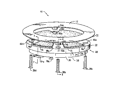
FIG. 1 is a perspective view of a junction box cover of the present invention.
FIG. 2 is a perspective view of a junction box lid of the cover of the present
invention.
FIG. 3 is a plan view of a junction box.
FIG. 4 is a cross sectional view of a ring and flooring material installed in
the
junction box cover of the present invention.
FIG. 5 is a plan view of the bottom of the junction box lid and two extensions
formed therewith of the cover of the present invention.
FIG. 6 is a cross sectional view of the cover installed in a junction box
taken along
sight Line 6-6 of FIG. 1.
FIG. 7 is a cross sectional view of the cover installed in the junction box
showing
one of the extensions taken along sight Line 7-7 of FIG. 1.
FIG. 8 is a side elevational view of a stop flange and a tang of the present
invention.
FIG. 9 is a side elevational view of two tangs of the present invention.
Detailed Description of the Preferred Embodiments)
The above and other features, aspects, and advantages of the present invention
will
now be discussed in the following detailed description and appended claims
while
2 0 considered in conjunction with the accompanying drawings in which
identical reference
characters designate like elements throughout the views. Shown in FIG. 1 is a
junction
bo:K cover 10 for an access port 42, as shown in FIGS. 2,3,6, and 7, which is
disposed
in
6
CA 02269303 1999-04-19
.4 . .
a junction box 40 adapted to be received at least partially within a floor
having a flooring
material 16a laid thereon, as shown in FIGS. 4, 6, and 7.
The junction box cover 10 includes a ring 12 that has a lower surface 32 and a
plurality of threaded bosses 14a, 146, 14c, and 14d extending downward
therefrom, as
shown in FIGS. 1 and 6. The ring 12 is substantially solid and preferably
constructed of
brass or steel for increased strength and durability and to thereby withstand
the forces of
heavy carts or machinery being rolled over top of the ring 12. The threaded
bosses 14a,
14b, 14c, and 14d of the ring 12 are for receiving screws 38a, 38b, 38c, and
38d or bolts
therein during assembly of the cover 10, as shown in FIGS. 1 and 6, and as
will be
discussed in greater detail below.
The access port 42, as shown in FIGS. 2, 3, 6, and 7, which allows access to
the
contents of the junction box 40, forms, in combination with the cover 10, a
junction box
cover assembly. The access port 42 has an outer annular member 48 with an
inner
surface SO and an upper surface 52. The access port 42 further includes an
inner annular
member 54 with an inside surface 56, a support surface 58 or mating surface,
and a
retention surface 46. At least one slot, but preferably two slots 44a and 44b
are disposed
in the inner annular member 54 and through which a portion of the cover 10 is
inserted
upon installation into the access port 42.
As shown in FIGS. 2 and 8, the slots 44a and 44b partially form a keyway 70,
which also includes a ramp 64 integrally formed on the inner annular member 54
and
extending from the slot 44a and the retention surface 46 as will be discussed
in greater
7
CA 02269303 1999-04-19
w ~ S
detail below. The access port 42 and associated junction box 40, in which the
port is
disposed, are preferably constructed of an aluminum, cast metal material for
increasing
strength and durability, but other material, whether cast or not, and whether
metal or not,
are equally suitable if the particular application warrants such. For
instance, a durable
plastic could also be used or metal material such as iron or steel.
As shown in FIGS. 1, 5, 6, and 7, the cover 10 further includes an annular
junction box lid 20, which is preferably substantially solid and also
constructed of cast
aluminum for increased strength and durability. The lid includes a first disc
22 with a
contact surface 24, a resting surface 26, and a plurality of bores 1 Sa, 15b,
15c, and 15d as
shown in FIGS. 6 and 7, extending therethrough. During installation of the
cover 10, the
contact surface 24 abuts the inner surface 50, of the outer annular member 48
and
simultaneously the resting surface 26 becomes supported by the support surface
58 of the
inner annular member 54, as is shown in FIGS. 6 and 7. The resting surface 26
forms a
first outer periphery.
A plurality of recesses 60a, 64b, 60c, and 60d are disposed in the first disc
22, as
best shown in FIGS. 1, 5, and 6, for each receiving, at least partially, one
of the threaded
bosses 14a, 14b, 14c, and 14d therein. Each of the recesses 60a, 60b, 60c, and
60d are
in axial alignment with one of the plurality of bores 1 Sa, 1 Sb, 1 Sc, and 1
Sd as shown in
FIG. 6. The cover 10 also includes a plurality of securing means, which
preferably
include screws 38a, 38b, 38c, and 38d or bolts as discussed above and shown in
FIGS. 1
and 6, but could also include any other threaded fasteners used in the
industry.
8
CA 02269303 1999-04-19
Each of the screws 38a, 38b, 38c, and 38d have a set length and are inserted
through one of the plurality of bores 15a, 1 Sb, 15c, and 1 Sd and
corresponding recesses
60a, 60b, 60c, and 60d to screwingly engage one of the corresponding plurality
of
threaded bosses 14a, 14b, 14c, and 14d for assembly of the cover 10. This
insertion is
prior to the cover 10 being installed in the access port 42. The plurality of
securing
means are unaccessible when the cover 10 is installed in the access port 42,
thereby
preventing the screws 38a, 38b, 38c, and 38d from loosening as heavy carts of
machinery
are rolled over the cover 10 and preventing the screws 38a, 38b, 38c, 38d from
being
unwantingly removed by an individual.
The cover 10 further includes a second disc 28 that is integrally formed with
the
first disc 22 and which has an outer surface 30 that abuts the inside surface
56 of the
inner annular member 54 when the cover 10 is installed in the access port 42 ,
as shown
in FIGS. 2 and 6. The outer surface 30 forms a second outer periphery that is
preferably
smaller in diameter than the first outer periphery of the first disc 22.
At least one extension, but preferably two extensions 34a and 34b, are
integrally
formed with the second disc 28 and protrude therefrom, as shown in FIGS. 1, S,
and 7.
During installation of the cover 10 in the access port 42, the extensions 34a
and 34b are
inserted through slots 44a and 44b, respectively. A stop flange 62 extends
downward
from the inner member 54 and prevents the cover 10 from being rotated in the
counterclockwise direction because one of the extensions 34a and 34b will abut
the stop
flange 62 upon insertion of the cover into the access port 42. The extensions
34a and
9
CA 02269303 1999-04-19
34b include an engagement surface 36 and as stated above, the ramp 64 extends
downward from the slot 44a such that when the extensions 34a and 34b are
inserted
through the slots 44a, 44b, respectively, and the cover 10 is rotated
clockwise, the
engagement surface 36 will contact the retention surface 46 of the inner
annular member
54 such that the cover 10 non-threadably engages the access port 42.
When the cover 10 is rotated, the ramp 64 gradually forces the cover 10 into
the
access port 42 and creates a tight fit between the two. The slot, or
preferably slots 44a
and 44b, as the case may be, the associated retention surface 46 of the access
port 42, and
the ramp 64 form the keyway 70 such that the cover 10 can be easily installed
into the
junction box 40 by being inserted and rotated in the keyway 70 only one way
and
similarly easily removed therefrom.
As best shown in FIG. 8, the inner annular member 54 further includes a tang
66
spaced from the slot 44a and formed therefrom, which prevents the cover 10
from being
excessively rotated in the clockwise direction. In the embodiment shown, tang
66 is
located to prevent cover 10 from being rotated more than a few degrees,
preferably ten
degrees or an amount of degrees spanning the width of the extensions 34a and
34b.
Commonly, the covers are inserted into the access ports sight unseen.
Therefore, the
present invention provides the tang 66 so that by abutment of one of the
extensions 34a
and 34b against the tang 66, an installer, without visual inspection, becomes
aware that
the cover 10 is fully inserted into the access port 42.
CA 02269303 1999-04-19
Moreover, by having the tang 66 preferably placed at the ten rotational
degrees
from the slot 44a, minimal rotation is required for installing the cover 10
into the access
port 42. The tang 66 prevents further clockwise rotation of the cover 10 once
secured in
the access port 42. It is understood, however, that the ramp 64, tang 66, and
stop flange
62 can be switched such that the cover 10 is rotated counterclockwise to be
installed in
the access port 42.
In an alternate embodiment, as shown in FIG. 9, opposing ramps 64 are formed
on either side of slot 44a such that the cover 10 can be rotated in either
clockwise or
counterclockwise direction for installation. Tangs 66 are provided as stops on
either side
of the slot 44a. Preferably, the ramps 64 and tangs 66 are only disposed on
either side of
one of the slots, but not both, although such could also be employed for an
increased
strength application.
A section 16 of the flooring material 16a, which is preferably substantially
annular
and the circumference of which equals the first disc 22 of the lid, as shown
in FIGS. 1, 4,
6, and 7, is disposed between the ring 12 and the lid 20 or against the upper
surface of lid
20. It is understood that the flooring material 16a, and section 16 thereof,
can be any
flooring material commonly used in the industry such as carpet, rubber, tile,
linoleum,
concrete, or wood, which has a given thickness. Once the cover 10 is
assembled, the
section 16 of flooring material 16a is in contact with the lower surface 32 of
the ring 12,
and is pressed or adhesively held against the first disc 22 of the lid 20. The
section 16 of
the flooring material 16a has a plurality of notches 18a, 18b, 18c, and 18d
cut therefrom,
11
CA 02269303 1999-04-19
. . , .
each receiving one of the threaded bosses 14a, 14b, 14c, and 14d therethrough
as shown
in FIG. 1. When the cover 10 is assembled, the section 16 of the flooring
material 16a is
partially exposed through the ring 12 for aesthetic purposes, as shown in FIG.
4.
The present invention further provides means for allowing for various
thicknesses
of the section 16 of flooring material 16a to be used in the cover 10. In
particular, by
increasing and decreasing the set length of the plurality of securing means,
or screws 38a,
38b, 38c, and 38d this enables differing thicknesses of the section 16 of
flooring material
16a to be used in the cover 10, depending on the flooring material 16a used in
a
particular application. For example, in a casino the flooring material 16a may
be
relatively thick carpet, but in a bank it may be relatively thin linoleum. The
present
invention is thus adaptable to receive various thicknesses for the section 16
of flooring
material 16a.
Although the invention has been described in detail above, it is expressly
understood that it will be apparent to persons skilled in the relevant art
that the invention
may be modified without departing from the spirit of the invention. Various
changes of
form, design, or arrangement may be made to the invention without departing
from the
spirit and scope of the invention. Further, although the above cover has been
discussed
in relation to floors, such a cover is equally suitable for covering junction
boxes that may
be placed in walls, ceilings, or other areas. Therefore, the above mentioned
description
is to be considered exemplary, rather than limiting, and the true scope of the
invention is
that defined in the following claims.
12