Note: Descriptions are shown in the official language in which they were submitted.
CA 02269392 2005-04-01
WET/DRY VACUUM WITH SNAP-ACTION POWERHEAD LATCH
2
3 FIELD OF THE INVENTION
4 This invention relates generally to the field of vacuum appliances, and more
6 particularly relates to a vacuum adapted to pick up wet and dry materials.
7
8 BACKGROUND OF THE INVENTION
9
Vacuum appliances capable of picking up both wet and dry materiai, commonly
11 referred to as wet/dry vacuums or weVdry vacs, are well-known. Wet/dry vacs
are often
12
13 used in workshops and other environments where both wet and dry debris can
14 accumulate.
Wet/dry vacs conventionally consist of a collection tank or canister,
sometimes
16
17 mounted on wheels or casters, and a powerhead within which a motor and
impeller
18 assembly is mounted. The motor and impeller assembly creates a suction
within the
19
canister, such that debris and/or liquid is drawn in to the canister through
an air inlet to
21 which a flexible hose can be attached. A filter within the canister
prevents incoming
22
23 debris from escaping from the canister while allowing filtered air to
escape. Any liquid
24 drawn into the canister is diffused and accumulates on the bottom of the
canister.
26 Wet/dry vacs are commercially available in a variety of sizes and
configurations.
27 The capacity, i.e., size, of a wet/dry vacuum collection canister is
typically measured in
28 gallons. In most if not all cases, the vacuum collection canister has a
round or
29
cylindrical configuration, since such a configuration represents the stablest
pressure
31 vessel, capable of withstanding the very large negative pressure (vacuum)
forces that
32
33 can be generated within a wet/dry vac.
34 Wet/dry vacs are also known in which the powerhead is detachable from the
36 coflection canister, enabling the powerhead to be used as a blower. These
types of
37 appliances are often referred to as blower/vacs. One example of a prior art
blower/vac
38
39 is U.S. Patent No. 5,606,769 to Tomasiak et al., entitled "Wet/Dry Utility
Vacuum
Cleaner with Detachable Btower." The Tomaskiak et al. '769 patent is commonly
assigned to the assignee of the present invention:
PAGE 1
CA 02269392 2005-04-01
2 SUMMARY OF THE INVENTION
3 The present invention is directed to a vacuum appliance having numerous
4 features believed to be advantageous. In one embodiment, the vacuum is of
the type
having a powerhead that is removable from the canister and lid, such that the
6 powerhead can be used separately as a blower.
7 In accordance with one embodiment of the invention, latching means are
8 provided for releasably securing the powerhead to the collection canister's
lid. In one
9 embodiment, the latching means is self-actuating, such that the powerhead is
automatically secured to the lid with a "snap action" when the powerhead is
lowered
11 into a recess defined in the lid for receiving at least a bottom portion of
the powerhead.
12 The self-actuation is facilitated by a spring biasing member that is
integrally formed with
13 the latching means.
14
In one embodiment, the latching means is a unitary, multi-segmented structure
including a journal adapted to be received in a bearing defined in a latch
socket on the
16
lid of the vacuum appliance. An integral retaining member is deflected as the
latching
17
means is installed into the socket, such that once installed, the latching
means cannot
18
19 be removed from the lid and is pivotally secured thereto.
In another embodiment, the latching means is a cantilevered structure. A
21 moment is induced by offseting the latching member from the front of the
cantilevered
22 structure, such that under load, the latch tends to tighten its engagement
with the
23 powerhead.
24 Accordingly then in one aspect, the invention provides a vacuum appliance,
comprising
a collection canister having a lid, a powerhead, adapted to be removably
secured to the
26 collection canister lid, and a latch for removably securing the powerhead
to the lid, the
27 latch being disposed in a latch socket formed in the lid, and the latch
having a journal
28 adapted to be received within a bearing defined in the latch socket for
permitting pivotal
29 motion of the latch with respect to the lid, the latch further comprising a
front member
3o and a rear member, a transverse rib member extending from the journal and
extending
31 between the front and rear members, a contacting member extending between
the front
32 and rear members and generally defining a top of the latch, a bottom member
extending
33 between the joumal and the rear member, and a retaining member extending
generally
34 rearwardly from the rear member wherein the latch socket is configured such
that the
latch is secured within the socket by the retaining member contacting a
bearing surface,
36 concentric to the first bearing defined in the socket.
PAGE 2
CA 02269392 2005-04-01
1 In another aspect, the invention provides a vacuum appliance, comprising a
2 collection canister having a lid, a powerhead, adapted to be removably
secured to the
3 collection canister lid, and latch means for removably securing the
powerhead to the lid,
4 the latch means being disposed in a socket formed in the lid, and the latch
having
joumal means adapted to be received within a bearing defined in the socket for
6 permitting pivotal motion of the latch means with respect to the lid, the
latch means
7 further comprising a front member and a rear member, a transverse rib member
8 extending from the journal and extending between the front and rear members,
a
9 contacting member extending between the front and rear members and generally
1o defining a top of the latch, a bottom member, extending between the joumal
and the rear
11 member, and retaining means extending generally rearwardly from the rear
member,
12 wherein the socket is configured such that the latch means is secured
within the socket
13 by the retaining means engaging an auxiliary bearing defined in the socket.
14 In another aspect, the invention provides a latch for removably securing a
powerhead to a lid of a vacuum appliance, the latch comprising a journal
adapted to be
16 received within a bearing defined in a latch socket defined in the lid, the
latch means
17 being disposed in a socket formed in the lid, and the latch having journal
means adapted
18 to be received within a bearing defined in the socket for permitting
pivotal motion of the
19 latch means with respect to the lid, the latch means further comprising a
front member
and a rear member, a transverse rib member extending from the journal and
extending
21 between the front and rear members, a contacting member extending between
the front
22 and rear members and generally defining a top of the latch, a bottom
member, extending
23 between the journal and the rear member, and retaining means extending
generally
24 rearwardly from the rear member, wherein the socket is configured such that
the latch
means is secured within the socket by the retaining means engaging an
auxiliary
26 bearing defined in the socket.
27 In another aspect, the invention provides a latch for removably securing a
28 powerhead to a lid of a vacuum appliance, the latch comprising a joumal
adapted to be
29 received within a bearing defined in a latch socket defined in the lid, the
joumal
permitting pivotal motion of the latch with respect to the lid, a front member
and a rear
31 member, a transverse rib member extending from the joumal and extending
between the
32 front and rear members, a contacting member extending between the front and
rear
33 members and generally defining a top of the latch, a bottom member coupled
between
34 the joumal and the rear member, and a retaining member extending generally
rearwardly from the rear member, wherein the latch socket is configured such
that the
PAGE 2a
CA 02269392 2005-04-01
I latch is secured within the socket by the retaining member engaging an
auxiliary bearing
2 defined in the socket, wherein the front member, rear member, transverse rib
member,
3 contacting member, bottom member, and retaining member are all substantially
planar,
4 the front and rear members being spaced apart and substantially parallel to
one another,
and wherein the latch is a unitary structure.
6 In another aspect, the invention provides a vacuum appliance, comprising a
7 collection canister having a lid a powerhead, adapted to be removably
secured at least
8 partially within a recess defined in the collection canister lid, and a
latch for removably
9 securing the powerhead to the lid, the latch being disposed in a latch
socket formed in
1o the lid, wherein the latch comprises a substantially planar cantilever
member, a latching
i i member, spaced back from a forward end of the cantilever member and
projecting
12 substantially perpendicularly up therefrom, and a spring member, disposed
generally at
13 the forward end of the cantilever member and projecting substantially
perpendicularly
14 down therefrom, wherein the latch socket is adapted to receive the
cantilever member
therein such that the latching member projects upward from the lid, the latch
socket
16 defining a spring retaining groove for securing a distal end of the spring
member, and
17 wherein when the powerhead is lowered into the recess, the latching member
engages a
18 latching rib defined on the powerhead, thereby securing the powerhead to
the lid.
19 In yet another aspect, the invention provides a latch for removably
securing a
powerhead at least partially within a recess formed in a lid of a vacuum
appliance, the
21 latch adapted to be disposed in a latch socket formed in the lid, wherein
the latch
22 comprises a substantially planar cantilever member, a latching member,
spaced back
23 from a forward end of the cantilever member and projecting substantially
perpendicularly
24 up therefrom, and a spring member, disposed generally at the forward end of
the
cantilever member and projecting substantially perpendicularly down therefrom,
wherein
26 the latch socket is adapted to receive the cantilever member therein such
that the
27 latching member projects upward from the lid, the socket defining a spring
retaining
28 groove for securing a distal end of the spring member, wherein when the
powerhead is
29 lowered into the recess, the latching member engages a latching rib defined
on the
powerhead, thereby securing the powerhead to the lid, and wherein the latch is
a unitary
31 structure.
32 In yet another aspect, the invention provides that a vacuum appliance,
33 comprising a collection canister having a lid a powerhead, adapted to be
removably
34 secured to the collection canister lid, and a latch for removably securing
the powerhead
to the lid, the latch being disposed in a latch socket formed in the lid, and
the, latch
PAGE 2b
CA 02269392 2005-04-01
1 having a joumal adapted to be received within a bearing defined in the latch
socket for
2 permitting pivotal motion of the latch with respect to the lid, the latch
further comprising a
3 retaining member adapted to engage an auxiliary bearing defined by the latch
socket
4 and ride against an auxiliary bearing surface thereof as the latch is
permitted to pivot
about the journal, the auxiliary bearing surface being concentric with the
bearing.
6
7 BRIEF DESCRIPTION OF THE DRAWINGS
$ The foregoing and other features and aspects of the present invention will
9 perhaps be best understood with reference to a detailed description of
specific
embodiments of the invention, when read in conjunction with the accompanying
t 1 drawings, wherein:
12 Figure 1 is a front view of a combination blower and vacuum appliance
13 ("blowerlvac") in accordance with one embodiment of the invention;
14 Figure 2 is a top view of the blower/vac from Figure 1;
PAGE 2c
CA 02269392 1999-04-21
AWD Ref.: ESPD:005
1 Figure 3 is a partially cut-away side cross-sectional view of a prior art
blower/vac;
2 Figure 4a is a side cross-sectional view of a powerhead latch from the prior
art
3 blower vac of Figure 3;
4 Figure 4b is a top view of the latch from Figure 4a;
Figure 5 is a partial side view of the blower/vac from Figure 1 showing the
6 powerhead thereof secured to the lid with a latch in accordance with one
embodiment
7 of the invention;
8 Figure 6 is a perspective view of the powerhead latch of the blower/vac from
9 Figure 1;
Figure 7 is an alternative perspective view of the powerhead latch from Figure
6;
11 Figure 8 is a partial side view showing a first stage of installation of
the
12 powerhead latch onto the lid of the blower/vac from Figure 1;
13 Figure 9 is a partial side view showing a second stage of installation of
the
14 powerhead latch onto the blower/vac from Figure 1;
Figure 10 is a partial side view showing a third stage of installation of the
16 powerhead latch onto the lid of the blower/vac from Figure 1;
17 Figure 11 is a partial side view showing a first stage of attachment of the
18 powerhead to the lid of the blower/vac from Figure 1;
19 Figure 12 is a partial side view showing a second stage of attachment of
the
powerhead to the lid of the blower/vac from Figure 1;
21 Figure 13 is a partial side view showing a first stage df detachment of
powerhead
22 from the lid of the blower/vac from Figure 1;
23 Figure 14 is a side view of a powerhead latching mechanism in accordance
with
24 an alternative implementation of the invention;
Figure 15 is an exploded perspective view of a powerhead latching mechanism
26 in accordance with an alternative embodiment of the invention;
27 Figure 16 is a partial cross-sectional view of the latching mechanism from
Figure
28 14 securing a powerhead to a blower/vac lid; and
29 Figure 17 is a partial cross-sectional view of the latching mechanism from
Figure
14 as the powerhead is being removed from the blower/vac lid.
PATENT APPLICATION OF STUART V. HOLSTEN ET AL. PAGE 3
H: 251597( 584T0I 1. DOC )
CA 02269392 1999-04-21
AWD Ref.: ESPD:005
1 DETAILED DESCRIPTION OF SPECIFIC EMBODIMENTS OF THE INVENTION
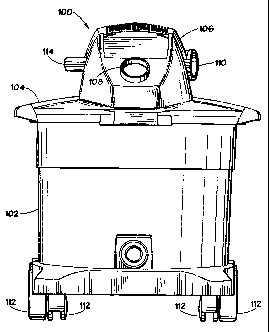
2 Referring to Figures 1 and 2, there are shown front and top views,
respectively,
3 of a combination blower and vacuum (blower/vac) 100 in accordance with one
4 embodiment of the present invention. As shown in Figures 1 and 2, blower/vac
100
comprises a collection canister 102 having a lid 104 and a detachable
powerhead
6 assembly 106 adapted to have a bottom portion thereof received within a
recess 118
7 defined in lid 104. Collection canister 102, lid 104 and the exterior
housing of
8 powerhead 106 are preferably made injection-molded plastic, such as
polypropylene or
9 the like, in accordance with conventional practice.
In accordance with conventional designs, an air inlet port 108 is defined in
lid
11 104 (or, alternatively, may be defined in a side wall of collection
canister 102).
12 Powerhead 106 houses a motor and impeller assembly, and has defined therein
an air
13 exhaust or outlet port 110. When operated in vacuum mode, the motor and
impeller
14 assembly functions to create a suction (negative pressure) within the
collection canister,
such that air is drawn in through inlet port 108, filtered, and exhausted
through air outlet
16 port 110. A flexible vacuum hose (not shown) has a proximal end adapted to
be
17 received, by friction-fit, for example, in vacuum inlet 108. One or more
accessory
18 nozzles (also not shown) can be fitted to the distal end of the hose, in a
conventional
19 arrangement.
With continued reference to Figures 1 and 2, canister 102 may be provided with
21 front and rear casters and/or wheels 112 for allowing blbwer/vac 100 to be
easily
22 transported.
23 The design and operation of a combination blower and vacuum as thus far
24 described herein are very well known to those of ordinary skill in the art.
It is believed
that it is therefore not necessary to discuss many of the design details, for
example, the
26 configuration of the filter assembly, construction of the motor and
impeller assembly,
27 and so forth, herein.
28 When it is desired to utilize powerhead 106 as a blower, powerhead 106 may
be
29 detached from lid 104, as will be hereinafter described in further detail.
A handle 114 is
formed in powerhead 106, such that powerhead 106 may be conveniently grasped
with
PATENT APPLICATION OF STUART V. HOLSTEN ET AL. PAGE 4
H: 251597( 5#4T0I ! DOC)
CA 02269392 2006-10-17
1 one hand, with air outlet 110 facing generally forward of the user. In the
blower mode of
2 operation, blower attachments, such as extension wands, blower nozzles and
the like,
3 may be attached to air outlet port 110, enabling the user to direct the
stream of air
4 exhausted from powerhead 106
. As those of ordinary skill in the art will appreciate, for a blower/vac
having a
6 detachable powerhead, it is desirable to provide a latching mechanism which,
while
7 reliably securing the power head to the canister lid during operation as a
vacuum, also
8 allows the powerhead to be easily released from the canister lid when it is
desired to
9 utilize the powerhead as a blower. One example of a prior art latching
mechanism is
1o disclosed in U.S. Patent No. 5,611,107 to Tomasiak et al., entitled
"Latching
11 Mechanisms for Wet/Dry Utility Vacuum Cleaner With Detachable Blower." The
12 Tomasiak et al. '107 patent is a continuation-in-part of the above-
referenced Tomasiak
13 '769 patent, is commonly assigned to the assignee of the present invention.
14
In Figure 2, a latching mechanism in accordance with one embodiment of the
16 invention is designated with reference numeral 116.
17 By way of comparison, Figure 3 is a partially cut-away cross-sectional view
of a
18 blower/vac 100' employing a prior art powerhead latching mechanism 116'.
The latching
19 mechanism 116' is also shown in the views of Figures 4a and 4b. (The
convention of
using "primed" reference. numerals in Figures 3, 4a, and 4b is adopted to
distinguish
21 corresponding components of blower/vac 100 from Figures 1 and 2 from the
prior art
22 blower vac of Figures 3 and 4). As with blower/vac 100 from Figures 1 and
2,
23 blower/vac 100' in Figures 3 and 4 includes a powerhead 106' which is
received in a
24 recess 118' in a collection canister lid 104'. The blower/vac of Figures 3,
4a, and 4b
corresponds generally to that disclosed in the above-referenced Tomasiak et
al. '769
26 patent.
27 As shown in the views of Figures 4a and 4b, the latching mechanism
comprises
28 a latch 116' having a journalled ends 120' pivotally mounted on lid 104',
such that latch
29 116' can be rotated as indicated by arrow 122' in Figure 4a. The spaced and
aligned
posts or journals 120' extend outwardly from latch 116' for reception within
5
CA 02269392 1999-04-21
AWD Ref.: ESPD:005
1 complementary shaped holes in spaced integral support plates 123' formed in
lid 104'
2 (see Figure 4a). The upper end of the releasable blower latch 116', in
alignment with
3 the spaced journals 120' include a series of aligned and spaced sections
125'
4 separated by openings 127', in order to allow the pivot posts or journals
120' to be
resiliently deformed inwardly relative to the complementary shaped mounting
holes
6 provided in the spaced support plates 123'. Once the spaced and aligned
journals 120'
7 are received within the complementary shaped mounting holes of the spaced
support
8 plates 123', the aligned and spaced sections 125' and 127' return to their
normal
9 condition for securing blower latch 116' in an assembled position relative
to the spaced
support plates 123' of lid 104'.
õ At an opposite end from journals 120', latch 116' includes an upstanding
handle
12 129' for moving the detachable blower latch 116' into engagement or
disengagement
13 relative to powerhead 104'. For this purpose, latch 116' includes a
flexible latching rib
14 124' that resiliently engages a lower locking shoulder 126' in a
complementary latch
opening 131' formed in the powerhead housing, as best illustrated in Figure
4a.
16 To detach powerhead 106' from lid 104', a user merely pulls down on a
handle
17 129' of latch 116'. To reattach powerhead 106', it is replaced into recess
118' as shown
18 in Figure 4a. Latch 116' must then be lifted up so that latching rib 124'
snaps into and
19 engages lower locking shoulder 126'.
There are some potential disadvantages of the simple latching mechanism 116'
21 of Figures 3 and 4. First, applied upward force from a user grasping or
lifting the vac by
22 handle 114' of powerhead 106' can tend to cause latching rib 124' to
deflect, weakening
23 the latching strength. Second, the latching operation is not automatic.
That is, the user
24 must actively snap latch 116' back into place once powerhead 106' is
replaced into
recess 118'. Third, latch 116' is not spring biased, i.e., there is no
constant force
26 present which tends to keep latch 116' in the latched position, thereby
avoiding
27 inadvertent detachment of powerhead 106'.
28 Turning now to Figures 5-13, there is illustrated a powerhead latching
29 mechanism 116 for blower/vac 100 in accordance with the presently disclosed
embodiment of the invention. As shown in the Figures, with blower/vac 100 in
the
PATENT APPLICATION OF STUART V. HOLSTEN ET AL. PAGE 6
H: 25 I 597( 584T0I I DOC)
CA 02269392 1999-04-21
AWD Ref.: ESPD:005
I vacuum mode, powerhead 106 is secured within a recess 118 in lid 104. A
pivot
2 mechanism comprising a pivot seat 130 and a lid pivot 128 provides a means
for
3 enabling powerhead 106 to be pivoted out from within recess 118. Latch 116
releasably
4 secures powerhead 106 at the back through engagement of a latching surface
132 over
a latching rib 134.
6 Figures 6 and 7 are alternative perspective views of latch 116 in accordance
with
7 the presently disclosed embodiment of the invention. Latch 116 is preferably
a unitary
8 (i.e., one-piece) structure made of molded polypropylene plastic or another
suitably
9 strong yet resilient material, as will hereinafter become apparent. As shown
in Figures 6
and 7, while it is a unitary structure, latch 116 essentially comprises or
defines multiple
11 structural components.
12 In particular, latch 116 comprises a substantially cylindrical journal 138
about
13 which latch 116 pivots, as well as a substantially planar front member 133
and a
14 substantially planar rear member 135 spaced apart from and generally
parallel to the
front member 133. A substantially planar reinforcing rib member 137 extends
from
16 journal 138 and extends transversely (although not necessarily at right
angles, as is
17 apparent from the Figures) between front and rear members 133 and 135. A
18 substantially planar bottom member 149 generally defines the bottom of
latch 116,
19 extending from journal 138 to rear member 135. A retaining member 150
extends
generally rearward from bottom 149 and rear member 135. A spring member 144
21 likewise extends generally rearwardly from rear member 135, from generally
near the
22 intersection of retaining member 150 and rear member 135. A contacting
member 164
23 extends between the front and rear members 133 and 135 at the end of latch
116
24 opposite journal 138.
The top of latch 116 is generally defined by contacting member 164 and a
finger
26 contact surface 166. The front of latch 116 is generally defined by front
member 133
27 and journal 138, and the rear of latch 116 is generally defined by rear
member 135,
28 from which retaining member 150, spring member 144, and a cover member 170
all
29 extend generally rearwardly.
PATENT APPLICATION OF STUART V. HOLSTEN ET AL. PAGE 7
H 25I 597(5lf4T01 !DOC)
CA 02269392 1999-04-21
AWD Ref.: ESPD:005
I In accordance with one advantageous aspect of the present invention,
latching
2 mechanism 116 requires no fasteners or the like to be permanently and
pivotally
3 secured to lid 104, and requires no tools to install or use. Figures 8-10
illustrate the
4 process of installing latching mechanism onto lid 104. First, as shown in
Figure 8, latch
116 is inserted journal-end (i.e., bottom) first into a socket 136 formed in
lid 104.
6 Journal 138 of latch 116 is adapted to be received in a C-shaped bearing
portion 139 of
7 socket 136.
8 Lead-in surfaces 140 and 142 formed in lid 104 assist in guiding latch 116
into
9 socket 136. As is apparent from Figures 9 and 10, as latch 116 is inserted
into socket
136, sliding and pivoting as indicated by arrows 146 and 148 in Figures 9 and
10, latch
>> biasing spring member 144 of latch 116 deflects around features of lid 104.
Just before
12 latch is completely installed, latch retaining member 150 contacts and
deflects (see
13 Figure 10) around a floor 152 of socket 136. When latch 116 is fully
inserted in socket
14 136, as shown in Figure 5, journal 138 seats in bearing 139, and retaining
member 150
"snaps" into an auxiliary bearing 154, riding against a bearing surface
defined by this
16 auxiliary bearing 154 as latch 116 is pivoted about journal 138. Also,
spring member
17 144 snaps onto a spring wall 156. Auxiliary bearing 154 is preferably
concentric with
18 latch bearing 139, defining a generally arcurate bearing surface against
which retaining
19 member 150 rides as latch 116 is pivoted.
Once installed, as shown in Figure 11, latch 116 is not intended to be
removable
21 from lid 104, and cannot be easily removed from lid 104: This is because
retaining
22 member 150 must deflect around socket floor 152 as latch 116 is being
installed, and
23 there is no access beneath retaining member 150 to pry or otherwise deflect
retaining
24 member 150 up and out of auxiliary bearing 154. Also, importantly, front
member 133 of
latch 116 bumps against a bump wall 160 defined by lid 104 to keep latch 116
from
26 rotating or pivoting far enough, in the direction urged by spring member
144, for
27 retaining member 150 to clear auxiliary bearing 154. (On the other hand,
pivoting of
28 latch 116 in socket 136 in the direction opposed by spring member 144 is
limited by
29 retaining member 150 coming into contact with a bottom surface 155 of
auxiliary
bearing 154.) Thus, notably, the pivoting of latch 116 in either direction is
restricted to
PATENT APPLICATION OF STUART V. HOLSTEN ET AL. PAGE 8
H 251597( 5N4T01 ! DOC)
CA 02269392 1999-04-21
AWD Ref.: ESPD:005
1 such an extent that retaining member 150 is prevented from disengaging
auxiliary
2 bearing 154 and hence functions to retain latch 116 within socket 136.
3 From Figure 5, it can be seen that when latch 116 is installed, spring
member
4 144 is preloaded in its home position, resting against and slightly
deflected by spring
wall 156. This biases 116 into a closed or latched position.
6 Turning now to Figures 11 and 12, the process of installing and latching
7 powerhead 106 onto lid 104 is illustrated. First, as shown in Figure 11, lid
pivot 131 is
8 inserted over pivot seat 130. Then powerhead 106 is lowered, by pivoting
pivot 131
9 within pivot seat 130. As it is lowered, as represented by arrow 162 in
Figure 12,
powerhead 104 contacts and slides along a contacting surface 164 of latch 116.
This
11 causes latch 116 to rotate outward about journal 138 and bearing 139.
Notably,
12 contacting surface 164 additionally contributes to the structure of latch
116, as it
13 extends between front and rear members 133 and 135.
14 It is to be noted that the more latch 116 rotates as it is deflected
outward by
powerhead 106 contacting contact surface 164, the more retaining member 150
rides
16 against the bearing surface of and engages auxiliary bearing 154, in turn
further
17 preventing latch 116 from being detached from lid 104.
18 As powerhead 106 continues to be rotated down, it eventually comes to rest
on
19 lid 104, and latch 116 "snaps" back, as a result of the deflection of
spring member 144,
such that latching surface 132 engages latching rib 134, as shown in Figure 5.
21 To unlatch powerhead 106 from lid 104, latch 116 is provided with a finger
22 contact surface 166 to which a user simply applies a light force, rotating
the latch back
23 in the direction of arrow 168 in Figure 13. This disengages latching
surface 132 from
24 latching rib 134, allowing powerhead 106 to be lifted up. In accordance
with one aspect
of the invention, this can be a one-handed operation, since the fingers of a
hand
26 grasping handle 114 can disengage the latch. Once disengaged, the hand
grasping
27 handle 114 can simply lift powerhead 106 up. Cover member 170 on latch 116
covers
28 the open space between the lid 104 and latch 106, preventing fingers from
being
29 caught therein.
PATENT APPLICATION OF STUART V. HOLSTEN ET AL. PAGE 9
H 251591(5#4T01 ! DOC)
CA 02269392 1999-04-21
AWD Ref.: ESPD:005
1 Latch 116 in accordance with the presently disclosed embodiment is believed
to
2 offer several advantages over powerhead latches of the prior art (such as
latch 116'
3 discussed above with reference to Figures 3 and 4). First, as described
above with
4 reference to Figures 8-10, no tools or fasteners are required to attach
latch to lid 104.
This is advantageous in terms of ease and cost of manufacture and assembly.
6 Additionally, notwithstanding the fact that no tools or fasteners are
required for
7 installation of latch 116, latch 116 is not subject to nuisance detachment
once attached.
8 The operation of retaining member 150 and bearing 154 ensure that latch 116
will not
9 accidentally become dislodged from its socket 136.
A further advantage of latch 116 over the prior art is its multiple wall
construction.
11 From Figures 3 and 4 it can be observed that some prior art latches
comprise a single
12 "walP' or a structural segment, while latch 116 comprises multiple
segments, including
13 front member 133, back member 135, bottom member 149, contacting surface
164,
14 transverse reinforcing rib member 137, and so on. This multiple-segment
configuration
gives latch 116 considerable strength as compared with single-segment prior
art
16 designs, making latch 116 less susceptible to deflection under load.
17 Also, as shown in Figures 6 and 7, the ends of journal 138 do not protrude
from
18 the rest of latch 116, as in prior art designs such as that discussed above
with
19 reference to Figures 3, 4a, and 4b. This prevents applied loads from
creating a lever
arm on journal 138, causing bending at the latch/journal interface. Instead,
loads
21 applied to latch 116 are applied evenly across the width thereof. Since
journal 138 is
22 integrally formed with the rest of latch 116, and hence essentially
comprises a part
23 thereof, there is considerably more contact area between journal 138 and
the body of
24 latch 116. This relieves stress concentrations that can build up on the
ends of a more
conventional journal or at the journal/latch interface.
26 The strength and reliability of latch 116 is believed to be enhanced due to
the
27 fact that journal 138 is a ring of material spanning the entire width of
latch 116, as
28 compared with, for example, the posts 120' previously discussed with
reference to
29 Figures 4a and 4b.
PATENT APPLICATION OF STUART V. HOLSTEN ET AL. PAGE 10
H: 251597(5k4T01 ! DOC)
CA 02269392 1999-04-21
AWD Ref.: ESPD:005
1 In addition, latching surface 132 is braced or gussetted by contact surface
164,
2 front member 133, rear member 135, and transverse rib 137, enabling latching
surface
3 132 to resist bending upward when loaded by blower/vac 100 being lifted by
handle 114
4 when powerhead 106 is still latched to lid 104. Bottom member 149 further
provides
support to latch 116. This gussetting effect can be further enhanced by
providing a
6 central supporting rib or wall-like structure (not shown in the figures)
extending
7 perpendicularly between front member 133 and rear member 135. Such a central
8 supporting structure may vertically extend all the way between contacting
member 164
s and bottom member 149.
Finally, latch 116 is self-actuating, requiring no active step on the part of
a user
11 to engage powerhead 106 when powerhead 104 is lowered onto lid 104. As
powerhead
12 106 is placed onto lid 104, latch 116 is temporarily deflected back against
the force of
13 spring biasing member 144. Once powerhead 106 is fully seated on lid 104,
spring
14 member 144 causes latching surface 132 to engage latching rib 134 with a
"snap."
In Figure 14, there is shown a side view of an alternative implementation of
latch
16 116 in accordance with the presently disclosed embodiment of the invention,
the
17 alternative implementation of Figure 14 being designated with double-primed
reference
18 numeral 116" (it being understood that those components of latch 116" which
are
19 substantially identical in form and function to those in the embodiment of
Figures 5-13
retain like reference numerals in Figure 14. The embodiment 116" of Figure 14
differs
21 from that of Figures 5-13 primarily in that the embodiment of Figure 14
includes a
22 connecting member 180 between finger contact surface 166 and cover member
170. It
23 is believed that the inclusion of connecting member 180 may further enhance
the
24 strength and stability of latch 116", and further tends to prevent an
operator's fingers
from sliding underneath finger contact surface 166 when pushing down thereon.
26 Turning now to Figures 15-17 there is shown a powerhead latching mechanism
27 in accordance with another alternative embodiment of the invention.
Referring first to
28 Figure 15, the latching mechanism in accordance with this alternative
embodiment
29 comprises a cantilevered latch 200 adapted to be received in a socket 202
formed in or
defined by lid 104 of vacuum 100. (It is to be understood that in Figures 15-
17, those
PATENT APPLICATION OF STUART V. HOLSTEN ET AL. PAGE 11
H: 251599(57F4T01! DOC)
CA 02269392 1999-04-21
AWD Ref.: ESPD:005
1 elements that are substantially identical to those in the earlier Figures
will retain
2 identical reference numerals; new reference numerals, such as latch 200 and
socket
3 202, will be used to identify elements that are different in the alternative
embodiment of
4 Figures 15-17.)
Cantilevered latch 200 is, like latch 116 of the previously disclosed
embodiment,
6 preferably a unitary structure made of molded polypropylene or the like.
Latch 200
7 comprises a cantilever member 206 adapted to be received in socket 202.
Cantilever
8 member is substantially planar, although a raised portion 207 may be defined
on an
9 upper surface thereof to provide a visual and tactile indication of how
latch 200 is
actuated to release powerhead 106 from lid 104, as will be hereinafter
described.
11 Cantilever member 206 is adapted to be secured in socket 202 by engagement
of
12 forward shoulders 205 thereof within slots 207 defined alongside socket
202.
13 A latching member 204 projects upward from cantilever member 206. Latching
14 member 204 is spaced back a distance X from a forward end 213 of cantilever
member
206, and projects up substantially perpendicularly to cantilever member 206.
Latch 200
16 further comprises a spring member 208, disposed generally at the forward
end 213 of
17 cantilever member 206, and projecting downward substantially
perpendicularly to
18 cantilever member 206.
19 Latching member 204 defines a latching surface 210 for engaging a latching
rib
216 defined in powerhead 106. Latching member further defines a contact
surface 211
21 against which powerhead 106 slides during reattachment of powerhead 106 to
lid 104.
22 During assembly, latch 200 is installed in lid 204 by sliding latch 200
into socket
23 202, as indicated by arrows 212 in Figure 15. The partially cut-away side
cross-
24 sectional view of Figure 16 shows latch 200 having been installed in this
manner. As
shown in Figure 16, when installed in lid 104, the distal end of spring member
208 is
26 received and retained within a spring retaining groove 214 in socket 202.
27 As in the previous embodiment, in the embodiment of Figures 15-17, a recess
28 118 is defined in lid 104 for receiving powerhead 106, or at least a bottom
portion of
29 powerhead 106, therein. Figure 16 shows latch latching surface 210 of
latching member
204 engaging a latching rib 216 defined in the housing of powerhead 106.
Notably, as a
PATENT APPLICATION OF STUART V. HOLSTEN ET AL. PAGE 12
H 251597(5R4T0I ! DOC)
CA 02269392 1999-04-21
AWD Ref.: ESPD:005
1 result of the offset X between front end 213 of cantilever member 206 and
latching
2 member 204, a latching moment is induced, such that under load, as
represented by
3 arrow 218 in Figure 15, latch 200 will tend to secure powerhead 106 even
more tightly
4 to lid 104.
To release powerhead 106, an operator depresses cantilever member 206
6 downward into socket 202, as represented by arrow 220 in Figure 16. This
downward
7 force will deflect cantilever member 206 into socket 202, causing a pivoting
at the front
8 end 213 of cantilever member 206. This pivoting, in turn, will cause
latching member
9 204 to be deflected back, as shown in Figure 17 and represented by arrow
222. In this
condition, powerhead 106 can be removed from lid 104.
11 As shown in Figure 17, the depression of cantilever member 206 and pivoting
12 about the front end 213 of cantilever member 206 also causes deflection of
spring
13 member 208, such that when cantilever member is released, latch 200 will
return to its
14 "home" position, that which is shown in Figure 16, under the spring force
of resilient
spring member 208. This spring biasing makes latch 200 self-actuating; that
is, no
16 active measure must be taken to cause latch 200 to engage powerhead 106
with a
17 snap action vihen it is placed back down on lid 104.
18 As noted above, when powerhead 106 is lowered back onto lid 104, it will
make
19 contact with contact surface 211 of latching member 204, causing latching
member 204
to be deflected back; when powerhead 106 is completely lowered into place on
lid 104,
21 latching member 204 will "snap" back into engagement with latching rib 216.
22 From the foregoing detailed description of specific embodiments of the
invention,
23 it should be apparent that a wet/dry vacuum appliance with a removable
powerhead for
24 separate use as a blower has been disclosed. Although specific embodiments
of the
invention has been described herein in some detail, it is to be understood
that this has
26 been done solely for the purposes of illustrating various aspects and
features of the
27 invention, and is not intended to be limiting with respect to the scope of
the claims. It is
28 contemplated that various substitutions, alterations, and/or modifications,
including but
29 not limited to those design alternatives that may have been specifically
noted herein,
PATENT APPLICATION OF STUART V. HOLSTEN ET AL. PAGE 13
H: 25 I 597(5B4T0I ! DOC)
CA 02269392 1999-04-21
AWD Ref.: ESPD:005
1 may be made to the disclosed embodiment without departing from the spirit
and scope
2 of the invention, as defined in the appended claims, which follow.
PATENT APPLICATION OF STUART V. HOLSTEN ET AL. PAGE 14
H_ 251597(5F4T011.DOC)