Note: Descriptions are shown in the official language in which they were submitted.
CA 02269579 1999-04-22
WO 98118702 PCT/US97/06128
1
METHOD AND APPARATUS FOR SPEED ENVELOPE PRINTING
BACKGROUND OF THE INVENTION
This application is a continuation-in-part
application of co-pending patent application Serial
No. 08/427,580, filed April 24, 1995, and entitled
"ENVELOPE CONSTRUCTION AND METHOD OF MAKING AND
DISPENSING SAME," which is incorporated herein by
reference.
SUMMARY OF THE INVENTIQN
The present invention relates in general to a method
and apparatus for high speed printing. More
particularly, the present invention relates to an
envelope construction which can be fed seriatim to non-
impact printers, and which can be dispensed from a kiosk
or the like.
For many business documents, standard size business
envelopes are used. However, because of the difficulty
associated with having such envelopes printed by a
non-impact desk top printer, such as laser and ink jet
printers, many people are still typing or manually
addressing envelopes, even in a business environment.
This process is time consuming, and is not consistent
with the speed of processing documents in a modern office
setting. Even when feeding a single conventional
multifold envelope into a non-impact printer, several
difficulties in printing the envelope arise. Usually,
the envelope is severely crumpled or puckered, and the
envelope may even jam the printer. Moreover, the heat
associated with laser printers and the moisture
associated with ink jet printers cause undesirable
CA 02269579 1999-04-22
WO 98/18702 PCT/US97/06128
2
effects on the envelope during the printing process. For
example, the gummed envelope can become inadvertently
sealed, rendering the printed envelope unusable.
Therefore, it would be highly desirable to have a new and
improved envelope construction, which could facilitate
printing of envelopes using non-impact printers without
the difficulties often times encountered in printing
conventional envelopes.
There have been various envelope constructions
invented to overcome this problem of wrinkling, puckering
and crumpling when passing through a printer. In this
regard, reference may be made to U.S. patents 5,377,904,
5,201,464, 4,898,323, 4,878,613, 3,968,927, 4,277,026,
3,823,867 and 4,784,317.
For example, in U.S. patent 4,878,613, a partially
constructed envelope is adapted to be fed into a laser
printer, which causes the completion of the forming of
the envelope as a result of the heat produced by the
laser printers. A line of heat activatable adhesive is
employed to facilitate this process.
After the envelope is formed, a portion of the
assembly must be removed, thereby leaving an undesirable
uneven, ragged edge. This also takes additional time and
creates wasted material. Therefore, it would be highly
desirable to have a new and improved envelope
construction, which would pass through non-impact
printers without being wrinkled, crumpled, puckered, or
otherwise damaged.
Even greater difficulties arise when attempting to
print numerous stacked-like envelopes using non-impact
printers. Due to the thickness of standard envelopes, it
is difficult, if not impossible, to feed large quantities
CA 02269579 1999-04-22
WO 98/18702 PCT/US97/06128
3
seriatim into a printer. When the gummed flap is folded
over in order to present a rectangular envelope to a
printer, the closed envelope does not have a constant
thickness. Thus, a large stack of such envelopes poses
the problem of having an uneven and non-uniform
configuration. With an uneven stack, it is difficult, if
not impossible, to feed properly and consistently a large
number of envelopes seriatim through a conventional sheet
feeder mechanism. Therefore, it would be highly
desirable to have a new and improved envelope
construction, which facilitates the reliable and
consistent feeding of large quantities of envelopes
without jamming or damaging the envelopes.
Another problem with many conventional envelopes, is
that a crease is formed where the gummed flap is joined
to the body of the envelope. This facilitates closing
the envelope. In some envelopes, the crease is formed by
scoring the paper. As a result, there is an impression
or indentation made in the paper, and when the envelopes
are stacked, they tend to nest at the score lines. When
nested envelopes are attempted to be fed into a
conventional sheet feeder, they do not singularize
readily and more than one can be presented inadvertently
to the feeder mechanism in an undesirable manner. As a
result, jamming of the feeder mechanism can occur.
Therefore, it would be highly desirable to have an
envelope construction, where large quantities of the
envelopes can be stacked and fed seriatim through a
conventional sheet feeder in a reliable and consistent
manner.
The printing of customized documents such as
greeting cards, at kiosks has become popular. Members of
CA 02269579 1999-04-22
WO 98/18702 PCT/US97/06128
4
the public who have access to such kiosks can create
personalized documents using computers and printers
associated with the kiosks. Therefore, it would be
highly desirable to have a new apparatus which dispenses
blank or customized envelopes from a kiosk-type
structure.
At the present time, dispensing envelopes from a
kiosk is extremely difficult, if not impossible, mainly
due to the fact that standard envelopes cannot be stacked
properly for proper presentation to a conventional sheet
feeder, due to the difficult problem of stacking
conventional envelopes. Any kiosk dedicated to
dispensing envelopes to the public would have to store
and feed a very large number of envelopes to keep
maintenance and restocking of the kiosk within reasonable
and profitable limits. In this regard, 500 or even 1,000
envelopes would be desirable. Therefore, it would be
highly desirable to have a new and improved apparatus for
dispensing envelopes at a public facility, free-standing
kiosk. Such an apparatus should be capable of storing
and delivering in a highly reliable manner, a large
number of envelopes.
The problem of storing a large quantity of stacked
envelopes is compounded in a high humidity environment.
Kiosks, while normally sheltered from the elements, may
be located in public areas, such as open malls and other
such locations, where the atmosphere is not necessarily
controlled. Thus, such kiosks may frequently encounter
high humidity environments.
CA 02269579 1999-04-22
WO 98/18702 PCT/US97/06128
Humidity can contribute to improper feeding of paper
products, such as paper sheets and paper envelopes. All
paper stock has a natural curl due to modern paper
manufacturing methods. This natural curl can become
5 greatly accentuated, when the paper absorbs moisture from
the atmosphere thereby causing the paper to curl. Paper
envelopes, when stacked to be fed through a conventional
sheet feeder mechanism, tends to warp and to curl in
higher humidity environments thus, making the envelopes
positioned askew in a stack, which thus becomes canted
and unstable. As a result, the envelopes are not
properly presented to the sheet feeder and can result in
improperly feeding the envelopes, and jamming can occur.
Therefore, it would be highly desirable to have an
envelope construction, which remains properly stacked,
even under high humidity conditions, for sheet feeding
purposes.
It is an object of the present invention to provide
a new and improved method and apparatus for high speed
printing in a reliable manner.
It is a further object of the present invention to
provide such a new and improved method and apparatus,
whereby envelopes can pass readily to and through
non-impact printers at high speeds without undue
wrinkling or jamming.
Briefly, according to the present invention, there
is provided a new and improved high speed envelope
printing method and apparatus which include an envelope
construction having a front panel with a flap sealing
adhesive strip on its back side, and a rear panel secured
to the front panel at its marginal edges to form a
pocket. The thickness of the adhesive strip is
CA 02269579 1999-04-22
WO 98/18702 PCT/LTS97/06128
6
substantially the same as the thickness of the rear panel
so that when the flap is opened, the overall
configuration of the envelope is flat to facilitate
stacking and feeding like envelope construction to and
through a non-impact printer at high speeds.
The combination of the strip and the rear panel are
both secured to the back side of the front panel, and the
combination adds a layer of a uniform thickness to
provide the desired flat aspect for stacking purposes. A
line of perforations in the front panel between the
adhesive strip and the rear panel with the flap portion
opened do not deform the front panel and thus interfere
with the high speed operation. The front and rear panels
have opposing curls facing each other to retain the flat
aspect of the envelope, even when the envelope absorbs
moisture, thereby facilitating the high speed operation.
A group of like such envelope constructions are
arranged in a stack within a paper tray. The topmost one
of the stack of like envelope constructions is separated
from the stack seriatim at high speeds to feed them
individually to the printer for printing thereon.
An advantage of the present invention is seen in the
fact that the novel construction of the envelope prevents
warping or curling in high humidity environments and this
attribute allows the envelope to be stored in large
quantities in a stacked arrangement. Thus, if desired,
the envelopes can be dispensed to the public from an
apparatus, such as a kiosk having an envelope dispensing
apparatus integrated therein at high speeds.
A further advantage of the present invention is that
since the envelope construction may be formed of two
separate panels, the two panels can be two different
CA 02269579 1999-04-22
WO 98/18702 PCT/US97/Ob128
7
sheets of paper, each having a different weight. In this
regard, a heavy bond paper can be used for the front
panel and a lighter weight bond can be used for the rear
panel when the envelopes are to be used in formal
correspondence applications. In this manner, a high
quality envelope results, and yet its overall weight is
lower, thereby reducing the cost of postage required.
BRIEF DESCRIPTION OF DRAWINGS
The above mentioned and other objects and features
of this invention and the manner of attaining them will
become apparent, and the invention itself will be best
understood by reference to the following description of
the embodiment of the invention in conjunction with the
accompanying drawings, wherein:
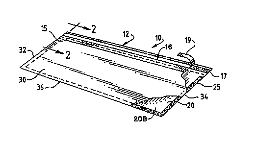
FIG. 1 is a partially cut away pictorial view of an
envelope construction which is constructed in accordance
with the present invention;
FIG. 2 is a fragmentary, enlarged sectional view of
the envelope construction of FIG. 1, taken substantially
on line 2-2 thereof;
FIG. 3 is an enlarged longitudinal sectional view of
the envelope construction of FIG. 1, illustrating the
opposing curl configurations of the front and rear
panels;
FIG. 4 is a diagrammatic view of an envelope
dispensing apparatus constructed in accordance with the
present invention;
FIG. 5 is a sectional view of a sheet feeder
apparatus for feeding the envelope construction of
FIG. 1, and which is constructed in accordance with the
present invention;
CA 02269579 1999-04-22
WO 98/18702 PCT/US97/06128
8
FIG. 6 is a plan view of the sheet feeder apparatus
of FIG. 5;
FIG. 7 is a sectional view of another sheet feeder
apparatus for feeding the envelope construction of
FIG. 1, and which is also constructed in accordance with
the present invention;
FIG. 8 is a plan view of the sheet feeder apparatus
of FIG. 7 illustrating a right justified feeding
position;
FIG. 9 is a plan view of the sheet feeder apparatus
of FIG. 7 illustrating a left justified feeding position;
FIG. 10 is a plan view of the sheet feeder apparatus
of FIG. 7 illustrating a center justified feeding
position;
FIG. 11 is a sectional view of another sheet feeder
apparatus for feeding the envelope construction of
FIG. 1, and which is also constructed in accordance with
the present invention;
FIG. 12 is a sectional view of the sheet feeder
apparatus of FIG. 11 in a rearward position;
FIG. 13 is a plan view of the sheet feeder apparatus
of FIG. 11 illustrating a right justified feeding
position;
FIG. 14 is a plan view of the sheet feeder apparatus
of FIG. 11 illustrating a left justified feeding
position;
FIG. 15 is a plan view of the sheet feeder apparatus
of FIG. 11 illustrating a center justified feeding
position;
FIG. 16 is a sectional view of another sheet feeder
apparatus which is constructed in accordance with the
present invention;
CA 02269579 1999-04-22
WO 98!18702 PCT/US97/06128
9
FIG. 17 is a plan view of the sheet feeder apparatus
of FIG. 16 illustrating a right justified feeding
position;
FIG. 18 is a plan view of the sheet feeder apparatus
of FIG. 16 illustrating a left justified feeding
position;
FIG. 19 is a sectional view of another sheet feeder
apparatus which is also constructed in accordance with
the present invention;
FIG. 20 is a plan view of the sheet feeder apparatus
of FIG. 19 illustrating a center justified feeding
position;
FIG. 21 is a sectional view of another sheet feeder
apparatus which is also constructed in accordance with
the present invention; and
FIG. 22 is a plan view of the sheet feeder apparatus
of FIG. 21 illustrating a center justified feeding
position.
DESCRIPTION OF THE PREFERRED EMBODIMENT
Referring now to the drawings, and more particularly
to FIGS. 1, 2 and 3 thereof, there is shown a new
envelope construction 10, which is constructed in
accordance with the present invention. The envelope
construction 10 can be readily and conveniently fed
through a non-impact printer, without having a tendency
to be peeled shut from the heat produced by a laser
printer (not shown) or the humidity produced by an ink
jet printer. Also, the envelope construction 10 will not
damage the printer fuser (now shown) of a laser printer,
since the construction 10 is protected from adhesive from
being inadvertently transferred therefrom to the printer.
CA 02269579 1999-04-22
WO 98/18702 PCT/US97/06128
Due to the novel construction of the envelope 10,
envelopes made in a manner of the envelope construction
10, can be stacked flat in a symmetrical manner without
leaning or tilting, and thus can be fed at high speeds
5 for envelope printing purposes as hereinafter described
in greater detail. The envelopes can be stocked in their
opened conditions, as indicated in FIG. 1, and can be fed
reliably through a conventional sheet feeder (not shown)
without adhesive contamination or premature self-sealing.
10 approximately 200 envelopes made like the construction
10 can be stacked in a conventional 500 sheet paper tray
(not shown) for feeding through a conventional non-impact
printer at high speeds.
The envelope construction 10, generally comprises a
large front panel on 20, and having a front side 20A, and
a backside 20B, so that a small rear panel 30 is disposed
in an overlying relationship on the backside 20B of the
front 20 and is secured in place thereof. At three
marginal edges 32, 34, and 36 to form an interior pocket
P (FIG. 1). The rear panel has a front side 30A and a
backside 30B. A flap portion generally indicated at 12
of the front panel 20 extends beyond the rear panel to
form a fold over flap for the envelope construction 10 so
that the contents (not shown? and the pocket P can be
retained in place in a convenient manner. In order to
secure the flap in its closed position, an adhesive strip
generally indicated at 16 extends across the backside 20B
of the front panel 20 at the flap portion 16 near one of
the its marginal edges so that the flap portion can be
sealed in a closed folded over position.
The rear panel 30 and the adhesive strip 16 are
generally of the same thickness to add a substantially
CA 02269579 1999-04-22
WO 98/18702 PCT/US97/06128
11
uniform thick layer to the backside 20B of the front
panel 20 to provide the envelope construction with a
generally flat aspect to enable a group of like envelope
constructions to be stacked evenly for sheet feeding
purposes.
As best seen in FIG. 3, the front panel 20 and the
rear panel 30 each assume its natural curl and in a
confronting relationship with one another to form a
symmetrical shape to help retain the overall symmetrical
shape of the construction constant, even when the panels
absorb moisture to facilitate greatly sheet feeding
purposes.
In order to maintain a flat aspect to the envelope
construction 10, a perforation line 15 in the front wall
20 extends between the adhesive strip 16 and the rear
panel 30 entirely across the longitudinal length of the
large front panel 20. The perforation line 15
facilitates the folding over of the flap portion 12.
Once the flap portion 12 is sealed in place, the envelope
construction 10 can be more readily opened, such as with
a letter opener (not shown) or similar tool. Also, in
accordance with the present invention, the perforation
line 15 does not deform the front panel 20, and thus the
envelope construction 10 assumes a flat configuration as
best seen in FIG. 2. The adhesive strips 16 includes an
adhesive line 17 covered over by a peal off backing strip
19. In this manner, the envelope construction 10 can be
fed through a sheet feeder (not shown) and into a non-
impact printer (not shown) without prematurely sealing
the envelope construction, since the adhesive 17 is of a
pressure sensitive type, and is covered over by the peal-
CA 02269579 1999-04-22
WO 98/18702 PCT/US97/06128
12
off backing strip 19. Strip 19 can be removed as shown
in FIG. 1 prior to sealing the envelope construction 10.
In order to assemble the envelope construction 10,
the front and rear panels are positioned in overlying
relationship as indicated in FIG. 2. In this regard,
three of the marginal edges are aligned as indicated at
32, 34 and 36. A U-shaped strip of adhesive 25 extending
along the three marginal edges, 32, 34 and 36 to fixed
together the two panels to form the pocket P.
The adhesive strip 16 is then secured to the
backside 20B of the front panel 20 and secured in place
by the adhesive 17. The perforation line 15 is formed by
conventional means (not shown) in the front panel 20
either prior to the assembly with the rear wall, or
afterwards.
Considering now the envelope construction 10 in
greater detail with reference to FIG. 2, the front panel
has a thickness T, and a rear panel 30 has a thickness
the rear panel 30 and the adhesive layer 25 have
20 thickness tl.
The adhesive strip line 17 and peel-off backing
strip 19 have a combined or overall thickness t2. A
uniform overall thickness in the envelope construction is
achieved by configuring the envelope components such that
tl substantially equals t2. In this regard, the rear
panel 30 and the adhesive line 25 have a combined
thickness tl substantially equal to the combined thickness
t2 of the adhesive strip 17 and the peel-off backing strip
19. This enables large numbers of the uniformly thick
symmetrical envelopes made according to the construction
10, to be stacked evenly without the stack being slanted
or leaning to one side. The result is that the novel
CA 02269579 1999-04-22
WO 98/18702 PCT/US97/06128
13
envelope construction facilitates reliable feeding and
continuous printing of large numbers of envelopes using
non-impact printers, without the difficulties encountered
in printing conventional multifold envelopes.
As indicated in FIG. 3, the panels 20 and 30 are
composed of paper material, and have a material curl,
which causes the paper sheet to be bowed from end to end,
as shown in FIG. 3, the curl becomes exaggerated in high
humidity environments as a result of the absorption of
moisture.
According to the present invention, the curl of the
paper material forming the front panel 20 and the paper
material forming the rear panel 30 are arranged in a
confronting relationship with one another to form a
symmetrical slightly elliptical shape. thus, when
moisture is absorbed, the panels 20 and 30 tend to bow
further away from one another, but they retain an overall
symmetrical configuration.
Each one of the panels 20 and 30 is composed of
paper material having a suitable thickness and stiffness
to enable the envelope construction 10 to be properly fed
through a sheet feeder. If there is too little
calendaring, the panel is too limp and does not have
sufficient body for the feeding. On the other hand, if
there is too great a calendaring, the resulting envelope
is too stiff, and it does not bend readily as it is fed
through a non-impact printer.
In accordance with the present invention, the panels
20 and 30 are each composed of paper material having a
caliper of between about 3.00 mils and about 5.50 mils.
The most preferred caliper is of 4.00 mils and a porosity
of about 11.0 Gurley units.
CA 02269579 1999-04-22
WO 98/18702 PCT/US97/06128
14
Additionally, the paper material forming the front
and rear panels should have sufficient surface smoothness
to be properly fed by a sheet feeder and then through a
non-impact printer. If the paper material is too slick,
it will not be fed properly. If the roughness is too
great, there is too much rag content in the paper
material and lint can form on the rollers (not shown) of
the equipment.
The paper material forming the front and rear panels
20 and 30 has a surface smoothness of between about 85
Sheffield and about 150 Sheffield. The most preferred
surface smoothness is about 100 Sheffield.
Referring now to the drawings, and more particularly
to FIG. 4 thereof, there is shown an envelope dispensing
apparatus 90, which is constructed in accordance with the
present invention. The envelope dispensing apparatus 90
is disposed within a protective housing 80 to serve as a
vending machine for the public.
The apparatus 90 is adopted to dispose envelopes in
their open positions, and one is made according to the
envelope construction 10 of FIG. 1. In operation, a
customer can make a payment for one or more of the
envelopes, and the envelopes are then dispensed to the
customer.
The envelope dispensing apparatus 90 includes a
payment mechanism 82, which will accept payment for
envelopes, in the form of coin, currency, or magnetic
strip credit/debit cards. The apparatus 90 also includes
a sheet feeder 84 connected to an envelope storage bin 86
containing a stack of like envelopes 88, each of which is
similar in construction to the envelopes construction 10
of FIG. 1. The stack of envelopes 88 can include a large
CA 02269579 1999-04-22
WO 98/18702 PCT/US97J06128
number of envelopes, such as 500 to 1000 envelopes. Due
to the unique flat, symmetrical construction of the
envelope, the stack is even, and the envelopes are fed
reliably through the feeder 84.
5 In operation, a customer would enter payment via a
payment chute 91. Once a proper payment has been
accepted, the payment mechanism 82 activates the sheet
feeder 84 via a electrical cable 93, which conveys a
signal from the payment mechanism 82 to the sheet feeder
10 84 to commence the feeding of envelope.
Upon activation, the sheet feeder 84 picks up
envelopes 88 seriatim stored in the bin 86, and moves
them through the envelope outlet slot 97, exposing the
envelope 95 to the customer (not shown). The customer
15 can then conveniently remove the disposed envelopes, such
as the envelope 95. The vending process can then be
repeated.
Because of the flatness, uniform thickness, and
resistance to curling or warping, the envelope
construction of the present invention makes it possible
to vend envelopes in this manner, even through the
apparatus 90 is located where the environment is not
regulated. High humidity has little or no affect on the
reliability of the vending of the unique envelopes.
Preprinted, custom printed, or blank envelopes can be
vended in this manner, depending upon the desired design
and related system employed.
Referring now to the drawings, and more particularly
to FIGS. 5 and 6 thereof, there is shown a sheet feeder
apparatus 510, which is constructed in accordance with
the present invention. The sheet feeder apparatus 510 is
received within a non-impact printer 502 to supply
CA 02269579 1999-04-22
WO 98/18702 PCT/US97/06128
16
envelopes, such as the envelope construction 10, thereto.
In this regard, the combination of the novel envelope
construction 10 and the sheet feeder apparatus 510 used
in accordance with the method of the present invention,
enables a group of like envelope constructions to be
printed at high speeds with little or no jamming in a
highly efficient and effective manner.
The sheet feeder apparatus 510 is a passive retard
type of sheet feeder, and is capable of supplying
20 envelopes to the printer 502 at the rate of up to about
envelopes per minute ("epm"). The sheet feeder
apparatus 510 includes a paper tray 512 having a bottom
member 513, a pair of vertical side walls 515 and 516
disposed on opposite sides of the bottom 513, and a
15 vertical front wall 514 connected to the bottom 513 and
disposed between the side walls 515 and 516. The bottom
513, the side walls 515 and 516, and the front wall 514
are sized and dimensioned to be received in the printer
502, and to receive and store a plurality of envelopes,
such as a stack 530 of envelopes for supplying the
envelopes to the printer 502 at a relatively high rate.
Each one of the envelopes is constructed in a manner
similar to the envelope construction 20 of FIG. 1.
A pair of guide members 519 and 520 are disposed
between the sidewalls 515 and 516, and spaced apart from
one another a sufficient distance to receive the stack
530 therebetween. The guide members 519 and 520 engage
opposite sides of the stack 530 to ensure that the
envelopes are supplied to printer 502 at an appropriate
location.
As shown in FIG. 6, the guide members 519 and 520
define a center justified feeding position. It will be
CA 02269579 1999-04-22
WO 98/18702 PCT/US97/06128
17
understood by one skilled in the art that the guide
members 519 and 520 may be adapted to define a right
justified feeding position or a left justified feeding
position. Furthermore, the spacing between the guide
members 519 and 520 may be adapted to receive various
sizes of envelopes as required.
A drive wheel 522 connected to an axle 526 engages
the stack 530 to facilitate the transportation of the
envelopes of the stack 530 to the printer 502. The
printer 502 includes a retard pad 504 disposed at about
the upper end of the front wall 514 for cooperating with
the drive wheel 522 to help separate the top most
envelope 532 of the stack 530 from the rest of the stack
530. A lift plate 518 disposed between the bottom 513
and the stack 530 urges the stack 530 upwardly to enable
the top envelope 532 to be engaged by the drive wheel
522.
Each of the envelopes of the stack 530 includes a
front side and a back side, wherein the front side
receives printer indicia thereon. The envelopes may be
stored in the tray 512 such that the front sides engage
the drive wheel 522. Alternatively, the envelopes may be
stored within the tray 512 so that the back sides engage
the drive wheel 522. In this regard, the envelopes may
be stored to accommodate the physical requirements of the
printer 502.
In use, the stack 530 is placed in the tray 512
between the guides 519 and 520. The forward portion of
the stack 530 is urged forwardly to engage the vertical
front wall 514 to ensure that the stack 530 remains in
place while the top envelope 532 is removed from the
stack 530.
CA 02269579 1999-04-22
WO 98/18702 PCT/US97/06128
18
The tray 512 is received within the printer 502,
wherein the front wall 514 is positioned adjacent and
below the retard pad 504, and wherein the drive wheel 522
engages the top envelope 532. The axle 526 rotates the
drive wheel 522 in a clockwise direction as indicated by
the arrow 524. The rotating drive wheel 522 engages the
top envelope 532 to move the top envelope 532 forwardly
as shown by the arrow 528. The forwardly moving top
envelope 532 engages the angled retard pad 504 to
facilitate the singulation or separation of the top
envelope 532 from the stack 530. Once separated from the
stack 530, the top envelope 532 is directed along a paper
path (not shown) within the printer 502 by conventional
paper feeding mechanisms.
Another sheet feeder apparatus 710 is shown in
FIGS. 7-10 for supplying envelopes to a printer (not
shown) and is also constructed in accordance with the
present invention. The sheet feeder apparatus 710 is
also a passive retard sheet feeder and is substantially
similar to the sheet feeder apparatus 510 (FIGS. 5 and
6). In this regard, the apparatus 710 includes a tray
712 having a bottom 713, side walls 715 and 716, and a
front wall 714 for storing a stack 730 of envelopes
therein. Unlike the sheet feeder apparatus 510, however,
the sheet feeder apparatus 710 includes an angled retard
pad 717 integrally connected to the upper portion of the
front wall 714. The angled retard pad 717 cooperates
with the drive wheel 722 rotating in a clockwise
direction as indicated by the wheel 724 for separating a
top envelope 732 from the stack 730.
As shown in FIG. 8, the apparatus 710 is adapted for
a right justified feeding position. A guide member 720
CA 02269579 1999-04-22
WO 98/18702 PCT/US97/06128
19
cooperates with the side wall 715 to receive the stack
730 therebetween. The rotating drive wheel 722 urges the
top envelope 732 forwardly as indicated by an arrow 728
to enable the top envelope 732 to engage the angled
retard pad 717, wherein the top envelope 732 is separated
from the stack 732.
A left justified feeding position for the apparatus
710 is illustrated in FIG. 9. In this regard, a guide
member 919 cooperates with the wall 716 to receive a
stack 930 of envelopes therebetween.
A center justified feeding position for the
apparatus 710 is shown in FIG. 10. A pair of spaced
apart guide members 1019 and 1020 are disposed between
the sidewalls 715 and 716, and receive the stack 1030
therebetween. In this way, the stack 1030 is positioned
within the tray 1012 between the side walls 1015 and
1016.
The sheet feeder apparatus 510 and 710 of FIGS. 5-10
are all passive retard devices, and are capable of
supplying envelopes at a rate of up to about 15 epm.
Higher envelope supply rates can be achieved using an
articulating/singulating arm type of sheet feeder
apparatus. In this regard, envelopes may be supplied at
a rate between about 15 epm and about 90 epm, with a jam
rate of 1 in about 10,000 or less, using an articulating
arm sheet feeder apparatus.
An articulating arm sheet feeder apparatus 1110 is
shown in FIGS. 11-15, and may be used to supply envelopes
to a printer (not shown) at a relatively high rate of
speed. The sheet feeder apparatus 1110 is described in
more detail in U.S. patent 5,377,969, which description
is incorporated by reference as if fully set forth
CA 02269579 1999-04-22
WO 98118702 PCT/US97J06128
herein. As described therein, the sheet feeder apparatus
1110 includes a tray 1112 having a bottom 1113 to support
a stack 1130 of envelopes. The tray 1112 further
includes a pair of spaced apart side walls 1115 and 1116
5 and an angularly inclined front wall 1114 disposed
between the side walls 1115 and 1116. The front wall
1114 is inclined upwardly from the bottom 1113 by between
about 21° and about 23°. An angled rear stop member 1118
is spaced apart from the front wall 1114 sufficiently to
20 receive the stack 1130, and to prevent the stack 1130
from moving rearwardly.
A guide member 1120 (FIG. 13) is fixed relative to
the bottom 1113, and spaced apart from the side wall
1115, to enclose the stack 1130 therebetween. Thus, the
15 apparatus 1110 of FIG. 13 defines a right justified
feeding position.
The guide member 1120 and the rear stop member 1118
are fixed relative to the bottom 1113 by securing
devices, such as screws 1140, 1142, 1145 and 1147. It
20 will be understood by one skilled in the art that other
methods of securing the guide member 1120 and the rear
stop member 1118 may also be used. For example, the
guide member 1120 and the rear stop member 1118 may be
slidably coupled relative to the bottom 1113 to adapt the
tray 1112 to various sizes of envelopes or paper stock.
The sheet feeder apparatus 1110 further includes an
articulating arm mechanism 1122 to facilitate the
singulation or separation of the top envelope 1132 from
the stack 1130, and to enable the top envelope 1132 to be
supplied to the printer. The articulating arm mechanism
1122 includes an elongated feed arm 1123, a separation
roller 1124 disposed at a forward end of the arm 1123 for
CA 02269579 1999-04-22
WO 98/18702 PCT/US97/06128
21
. engaging the top envelope 1132, and an arm shaft 1126
disposed at a rear end of the arm 1123 for moving the
articulated arm mechanism 1122 forwardly and rearwardly
relative to the tray 1112.
In operation, the separation roller 1124 engages the
top envelope 1132 of the stack 1130, and rotates in a
clockwise direction as indicated by the arrow 1125 to
provide a sufficient force to overcome the sliding
friction between the envelopes of the stack 1130. As a
result, one or more of the upper envelopes in the stack
1130 are moved forwardly to engage the front wall 1114
which defines a feed wall or ramp.
The articulating arm 1122 (FIG. 12) is moved
rearwardly relative to the front wall 1114 to move the
separation roller 1124 rearwardly along the top envelope
1132. As the articulating arm 1122 moves rearwardly, the
top envelope 1132 is buckled until the beam strength of
the envelope 1132 is overcome.
The top envelope 1132 moves up the front wall 1114
while the next adjacent envelope in the stack 1130 is
stopped by the front wall 1114. In this way, singulation
and feeding of the envelopes is facilitated.
A left justified feeding position for the apparatus
1110 is shown in FIG. 14. In this regard, a guide member
1419 is spaced apart from the side wall 1116 to receive a
stack 1430 therebetween. In addition, a rear stop member
1418 is spaced apart from the front wall 1114 to help
restrain the stack 1430 therebetween.
A center justified feeding position for the
apparatus 1110 is illustrated in FIG. 15. A pair of
spaced apart guide members 1519 and 1520 are disposed
CA 02269579 1999-04-22
WO 98!18702 PCT/US97/06128
22
between the side walls 1115 and 1116 for maintaining the
stack 1530 in a central portion of the tray 1512.
Thus, depending upon the printer path of a printer,
the appropriate feeding justification for the sheet
feeder apparatus 1210 can be selected to supply envelopes
at an extremely high rate with acceptable jam rates.
Another sheet feeder apparatus 1610 is illustrated
in FIGS. 16 and 17, and is also constructed in accordance
with the present invention. The sheet feeder apparatus
1610 is a corner buckler type of device, and is capable
of supplying envelopes at the rate of up to 30 epm to an
associated printer (not shown).
The sheet feeder apparatus 1610 is similar to the
apparatus 510 (FIGS. 5 and 6}, AND includes a tray 1612
having a bottom 1613, a pair of spaced apart side walls
1615 and 1616, and a vertical front wall 1614 disposed
between the side walls 1615 and 1616.
The apparatus 1610 defines a right justified feeding
position, and includes a guide member 1620 spaced apart
from the side wall 1615 to receive a stack 1630 of
envelopes therebetween.
A lift plate 1618 urges the stack 1630 upwardly to
enable a top most envelope 1632 to engage a drive wheel
1622. The drive wheel 1622 is driven by an axle 1626 in
a clockwise direction as indicated by the arrow 1624 to
help singulate the top envelope 1632.
A corner member 1621 is disposed at about the
junction of the front wall 1614 and the side wall 1615
for buckling the envelopes. In this regard, the corner
member 1621 is fixed above the stack 1630 when the stack
1630 is received between the guide member 1620 and the
sidewall 1615.
CA 02269579 1999-04-22
WO 98/18702 PCT/US97/06128
23
. In use, the drive wheel 1622 engages the top
envelope 1632 and urges it forwardly as the drive wheel
1622 rotates in the clockwise direction. The top
envelope 1632 is restrained by the corner member 1621 as
the envelope 1632 is urged forwardly, wherein a buckle
1634 (FIG. 16) develops in the top envelope 1632. Once
buckled, the top envelope 1632 is singulated from the
stack 1630 and sent over to the printer.
Another sheet feeder apparatus 1810 is shown in
FIG. 18 for supplying envelopes to a printer (not shown),
which is also constructed in accordance with the present
invention. The apparatus 1810 is substantially similar
to the apparatus 1610, except that the apparatus 1810
defines a left justified feeding position. In this
regard, the apparatus 1810 includes a tray 1812 having a
corner member 1821 disposed at about the junction of a
side wall 1816 and a front wall 1814 for facilitating the
singulation of the envelopes. A guide 1819 spaced apart
from the side wall 1816 is adapted to receive a stack
1830 of envelopes therebetween.
Referring now to FIGS. 19 and 20, there is shown
another sheet feeder apparatus 2010, which is also
constructed in accordance with the present invention.
The sheet feeder apparatus 2010 is an active retard
device and is capable of supplying envelopes at a rate of
up to about 90 epm. The apparatus 2010 includes a tray
2012 which is substantially similar to the tray 712
(FIG. 7), and includes a bottom 2013, a pair of spaced
apart vertical side walls 2015 and 2016, and a front wall
member 2014 disposed between the side walls 2015 and
2016.
CA 02269579 1999-04-22
WO 98/18702 PCT/US97/06128
24
A pair of guide members 2019 and 2020 (FIG. 20)are
spaced apart from one another between the side walls 2015
and 2016 to define a center justified feeding position.
The spacing between the guide members can be adjusted for
receiving a stack 2030 of envelopes of various sizes
therebetween. A lift plate 2018 urges the stack 2030
upwardly into engagement with a drive wheel 2022 to
facilitate the supply of envelopes to a printer (not
shown). The drive wheel 2022 is rotated by an axle 2026
in a clockwise direction indicated by the arrow 2024 to
urge the top most envelope 2032 forwardly.
When received within the printer, an active retard
roller 202 is positioned at about the front wall 2014.
The active retard roller 2002 rotates in a clockwise
direction indicated by the arrow 2004 to engage the
envelopes for preventing them from entering the printer
feed path (not shown), thereby enabling the top envelope
2032 to be separated from the stack 2030. The separated
envelope 2032 engages a feed roller 2006 rotating in a
clockwise direction indicated by the arrow 2008 to feed
the separated sheet 2032 to the printer along the feed
path.
Another sheet feeder apparatus 2110 is shown in
FIGS. 21 and 22 for supplying envelopes to a printer (not
shown), and is also constructed in accordance with the
present invention. The apparatus 2110 is substantially
similar to the apparatus 2010 (FIGS. 19 and 20), except
that the drive wheel 2022 of the apparatus 2010 has been
replaced by a vacuum pick shuttle 2105 in the apparatus
2110.
The vacuum pick shuttle 2105 engages a topmost
envelope 2132 from a stack 2130 of envelopes to
CA 02269579 1999-04-22
WO 98/18702 PCT/US97/06128
facilitate the supply of the envelopes to the printer.
The shuttle 2105 is movable forwardly and rearwardly
relative to the stack 2130 to enable the top envelope
2132 to be singulated or separated from the stack 2130.
5 In use, the shuttle 2105 is positioned at an initial
position to engage the top envelope 2132, wherein the
initial position is indicated by dashed lines. The
shuttle 2105 engages the top envelope 2132, and is moved
forwardly as indicated by arrow 22106 to a feeding
10 position shown in solid lines, wherein the top envelope
2132 is singulated from the stack 2130 and supplied to
the printer.
The shuttle 2105 returns to the initial position,
traveling rearwardly as indicated by arrow 2107, to
15 engage the next envelope in the stack 2130. The process
is repeated until a desired amount of envelopes have been
supplied.
While particular embodiments of the present
invention have been disclosed, it is to be understood
20 that various different modifications are possible and are
contemplated within the true spirit and scope of the
appended claims. There is no intention, therefore, of
limitations to the exact abstract or disclosure herein
presented.