Note: Descriptions are shown in the official language in which they were submitted.
CA 01269775 1001-O1-11
Page /
~XPANDA',
Field of the
Resiliently expandable sleeves, tapered for nestability in storage, serve as
protective
separators for articles placed vertically in a container.
Prior Art
Various methods for protective separation of bottles placed vertically in a
container include:
simple strips of paperboard placed between said bottles; or moulded devices
for positioning
said bottles at their tops and bottoms as described in U.S. Patent No.
4,625,908 (Emery, 1986)
and accordion folded packaging as described in U.S. Patent No. 4,485,610
(Galley et al, 1984)
and U.S. Patent No. 5,379,946 (Fanery, 1995). A moulded plastic bottle carrier
comprised of
a multiplicity of tapered pockets, each said pocket having eight side walls
connected together at
the full length of their adjacent edges, adjacent pockets of said carrier
being connected together
into a group of two rows of pockets, at the upper edges of their respective
adjacent side walls
by means of a plastic horizontal web, and suspended from a single handle for
hand transport of
said bottles in said carrier, said web having a width designed to avoid
injurious contact
between adjacent bottles caused by the swaying together of the upper sections
of said bottles
projecting above said pockets while said bottles in said carrier are
transported by hand carry,
as described in U.S. Patent No. 3,115,266 (Poupitch, 1963).
Su~nmarv of the Invention
It is the object of this invention to create a tapered, resiliently
expandable, soft moulded pulp
sleeve to provide a clasping pressure over a predetermined area of the article
contained therein.
Said sleeves as formed are each comprised of four side walls of similar shape
and dimensions
with a preferred wall thickness of one millimeter to provide a soft cushioning
effect between
bottles contained in adjacent sleeves in close contact with each other, said
side walls being
co~ected together at their adjacent edges, each tapered from the width at its
upper end
designed to provide a square opening in said sleeve to permit free entry of
said article, to a
smaller width at the opposite end thereof, each of said side walls being
tapered in width
symmetrically and sufficiently to provide a downwardly and inwardly slope in
each portion of
each said side wall to guarantee free movement in denesting from multiple
storage in stacks of
said sleeves, or in stacks of interconnected groups thereof. And each of said
side walls of each
said sleeve is designed to be deflected outwardly of said sleeve by the
further entry of said
article, to accommodate the shape and size of said article in the areas of
contact therewith at
that point in the taper of said sleeve, thereby creating a clasping pressure
of said side walls
upon the exterior of said article. The resilient outwardly deflection of said
side walls will
permit the further insertion of said article, along the length of said sleeve
only to a point
where the total connected internal circumference of said side walls is
approximately equal to,
but not less than, the circumference required to accommodate the size and
shape of the
contained article. Because of the degree of taper created by the angle of
slope, preferably one
part horizontally in four parts of vertical height, to accommodate the soft
texture and wall
thickness of said soft moulded side walls, and where a longer length of sleeve
is required
contirnling beyond that point with continuing taper, then compensating details
will be required
to permit the further entry of said article.
CA 01169775 1001-O1-11
Page
A first preferred embodiment of the invention is a group comprised of a
multiplicity of said sleeves,
each said sleeve being comprised of four tapered planar side walls of
identical shape and size
connected together at their adjacent edges with their wider upper edges
forming the rim of a square
opening at the upper end of each said sleeve, each side of said opening having
a width equal to the
diameter of a cylindrical glass bottle to provide free entry thereof at that
level. Each said sleeve is
tapered to smaller dimensions at its lower end, each said side wall thereof
being tapered
accordingly to a smaller width at its lower end. Said multiplicity of sleeves
are connected together
at the adjacent upper edges of their respective side walls to form as
interconnected group arranged
in rows to conform with the dimensions of the intended container. The
connections between the
adjacent side walls of each of said sleeves of said group are discontinued
beyond a predetermined
point in the length of each said sleeve where the sum total of the widths of
said four side walls of
said sleeve is becoming less than the circumference of said cylindrical glass
bottle to be contained
therein, thereby allowing the further outwardly deflection of the remaining
lower portion of each of
said side walls required to permit the entry of said bottle to the full length
of said sleeve.
In a second preferred embodiment of the invention, in another group comprised
of a multiplicity of
said sleeves, each said sleeve in said group is tapered sufficiently to
provide nestability in storage,
and each of its four tapered side walls is formed with a tapered depression
projecting inwardly of
said sleeve and extending along the length thereof, tapering from a minimum
dimension at or close
to the upper edge of each said side wall and increasing in depth and width to
a larger dimension at
the opposite end thereof, thereby providing for an increase in effective width
of each said side wall
relating in its extent to the dimensions of said depression at each point in
the length thereof, and to
the extent of the outward deflection of said depression caused by the entry of
the article to be
contained therein.
In a third preferred embodiment a gmup of 12 bottles in a 24 pack container
are entered into a
corresponding interconnected group of 12 of said sleeves, and retained in
place at their top ends by
a reinforced panel of 12 interconnected tapered cells, each of said panels
having reinforcing ribs
with glue faces for attachment to the inner face of the corresponding inner
cover flaps of said
container.
Brief Description of the Drawings
Figure 1 is a plan view of an interconnected group of 4 tapered sleeves
designed to protect and
retain in position 4 short bottles placed vertically in a container.
Figure 2 is an end view of said group of sleeves of Figure 1.
Figure 3 is an elevation view of said short bottles placed vertically in said
sleeves of Figures 1 and
2.
Figure 4 is a plan view of a group of 4 elongated and interconnected sleeves
designed to protect and
retain in position 4 longer bottles placed vertically in a container.
Figure 5 is an elevational view of said group showing the tapered shape of
said sleeves prior to the
entry of said bottles.
Figure 6 is an elevational view of said longer bottles entered into said
sleeves of Figures 4 and S.
CA OZ269775 1999-OS-07
Figure 7 is a plan view of an interconnected group of 12 of said tapered
sleeves, each side wall
of each said sleeves having been moulded with a stabilizing horizontal flange
at the bottom end
of said sleeve.
Figure 8 is a plan view of a reinforced panel of tapered cells provided with
two reinforcing
ribs.
Figure 9 is a cross-sectional view taken at line 4-4 of Figure 8.
Figure 10 is a cross-sectional view taken at line 5-5 of Figure 8.
Figure 11 is a cross-sectional view taken at line 6-6 of Figure 8.
Figure 12 is a cross-sectional view of bottles in a half portion of a
container said bottles having
been entered into said sleeves of Figure 7.
Detailed Description of the Embodiments
The tapered sleeves 100 of the group 1000 shown in Figures l, 2 and 3 are each
sufficient in
height to enwrap the entire length of the cylindrical portions of bottles 110
which they were
designed to separate and protect from injurious contact with each other. Each
of said sleeves
100 is comprised of two side walls 101 at the interior of said group 1000, and
two side walls
103 at the exterior of said group, said sleeves being connected together at
adjacent side walls
101 by connecting bands 102. Each of said four side walls of each of said
sleeves 100 has a
wider width at its upper edge, the upper edges of said four side walls of each
said sleeve
together forming a square opening of sufficient dimension to allow free entry
of the bottle 110
which it has been designed to receive. Each of said four side walls of each of
said sleeves is
tapered to a smaller width at its lower edge, in conformity with the taper of
said sleeve.
At line 1-1 of Figure 3 the total sum of the tapered widths of the four side
walls at that
location is only sufficiently greater than the circumference of said
cylindrical portion of said
bottle 110 to tolerate the required outwardly deflection of said side walls to
conform with and
encircle the exterior of said bottle 110. Below that level the connection
together of said four
side walls at their adjacent edges is discontinued at division lines 104, in
order to allow the
further outwardly deflection of the continuing lower portions of said side
walls required to
conform with the shape and size of the areas of said bottle contacted by said
side walls.
The sleeves 200 of group 2000 shown in Figures 4, 5 and 6 are made suffciently
long
to a ~e entire length of the cylindrical portions of the longer bottles 210.
The required
continuing taper of said sleeves 200 in order to provide for nesting of said
sleeves in storage
necessitates special design features to stabilize the longer length of side
wall portions
disconnected from each other, and to provide a sufficient width of side wall
material at the
lower end of each said side wall to ensure protective separation of adjacent
bottles. The shape
and dimensions of an inwardly directed depression 205 formed in each of said
side walls, and
CA 02269775 1999-05-07
4
tapering from a minimum dimension at the upper edge of said side wall to a
larger dimension
at the lower edge thereof are shown in plan and elevation in Figures 4 and 5
respectively.
Also shown are the optional division lines 204 indicating the length of
disconnection if
required between the edges of adjacent side walls at corners 206 in each of
said sleeves.
Figure 6 is an elevational view showing bottles 210 already inserted in said
sleeves 200 of said
group 2000, and indicating said depressions 205 in said inner side walls 201
being pressed
together to separate adjacent bottles 210 and said outer side walls 203 being
stretched and
further separated at said division lines 204 in order to conform with the
shape of the exterior
of said bottles at that location. Said depressions 205 also provide
stabilizing column strength
to each of said side walls 201 and 203 during the entry therein of said
bottles 210.
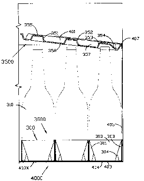
The system of bottle separators illustrated in Figures 7 through 12 requires
the combined use
of the group 3000 of sleeves 300 together with the panel 3500 of tapered cells
351, 352 and
353 and the container 4000. Shown in Figure 7 is a plan view of said group
3000, comprised
of twelve interconnected tapered cells 300, each of said cells 300 being
comprised of four
tapered side walls, each said side wall being moulded with an optional
horiwatal flange 30 at
its lower edge. Adjacent side walls 301 are interior of said group and are
connected together
in pairs at lines 308. Side walls 303 together form the exterior side walls of
said group 3000.
Each said cell has an opening 354 in the top wall thereof.
The four side walls of each sleeve 300 each have an upper edge, and said four
upper edges
together form the rim of a square opening at the upper end of each said sleeve
300, the width
of each said side wall being tapered in width from the width of said upper
odge to a smaller
width at its lower edge, to conform with the taper of the related sleeve. The
connection
together of the adjacent side walls of each said sleeve 300 at corners 306 is
discontinued at
separation lines 304 in order to permit the outward deflection of those
disconnected portions
of said side walls at the four corners of each said square opening whereby to
widen the free
space between said side walls at the upper ends thereof, and thereby to admit
the entry of
bottles of predetermined larger diameters at said rim of said square opening.
Each connecting line 308 between said side walls 301 is discontinued at lines
308 X at each
end thereof in order to allow the expansion of said square opening at the top
of each said cell
300 in order to allow the entry of a bottle of larger diameter than the width
and 1of said
square opening, thereby to permit the use of said group 3000 and said sleeves
thereof to
accommodate a limited range of bottles larger in diameter than the length or
width of said
square opening at the upper end of said sleeves.
Said panel 3500 is shown in plan view in Figure 8, and is provided with two
reinforcing ribs
357, each with a gluing face 358 for attachment to the inner face of an inner
cover flap 401
of the container 4000, as shown in Figure 12. Said panel 3500 is surrounded by
a reinforcing
flange 356 directed upwardly and outward from the connecting body of said
panel, in order to
facilitate the entry of said panel into said container. Each said panel 3500
is moulded with 12
tapered cells located to retain in position each of twelve said bottles 310,
said cells being in
three rows with four said cells in each row, a first row of cells 353 located
nearest the hinge
CA 01169775 1999-OS-07
line 407 having an elongated taper 354 at the side nearest said hinge line 407
whereby to avoid
obstructive contact between said adjacent side 354 aad the top of a
corresponding bottle 310
during the closing action of said inner cover flap 401. The four cells 352 in
the i~ermediate
row of cells have an extended taper at the side nearest said hinge line 407
designed to retain
said top of the related bottle 310 when said inner cover flap 401 is in the
closed position, and
the row of four cells 351 nearest the outar edge of said panel 3500 has a
uniform taper
designed to retain the corresponding bottle tops in their intended positions.