Language selection

Search

Patent 2270012 Summary

Third-party information liability

Some of the information on this Web page has been provided by external sources. The Government of Canada is not responsible for the accuracy, reliability or currency of the information supplied by external sources. Users wishing to rely upon this information should consult directly with the source of the information. Content provided by external sources is not subject to official languages, privacy and accessibility requirements.

Claims and Abstract availability

Any discrepancies in the text and image of the Claims and Abstract are due to differing posting times. Text of the Claims and Abstract are posted:

  • At the time the application is open to public inspection;
  • At the time of issue of the patent (grant).
(12) Patent: (11) CA 2270012
(54) English Title: FLOATING DOCK SECTION
(54) French Title: ELEMENT DE QUAI FLOTTANT
Status: Term Expired - Post Grant Beyond Limit
Bibliographic Data
(51) International Patent Classification (IPC):
  • B63C 1/02 (2006.01)
(72) Inventors :
  • ZEILINGER, BRIAN K. (United States of America)
(73) Owners :
  • PLAYSTAR, INC.
(71) Applicants :
  • PLAYSTAR, INC. (United States of America)
(74) Agent: SMART & BIGGAR LP
(74) Associate agent:
(45) Issued: 2005-10-25
(22) Filed Date: 1999-04-22
(41) Open to Public Inspection: 1999-10-24
Examination requested: 2002-03-20
Availability of licence: N/A
Dedicated to the Public: N/A
(25) Language of filing: English

Patent Cooperation Treaty (PCT): No

(30) Application Priority Data:
Application No. Country/Territory Date
60/082,893 (United States of America) 1998-04-24

Abstracts

English Abstract

A dock, pier or floating deck wherein the sections comprising the dock include a wheel support and a wheel mounted thereon to enable easy movement of the dock section over the surface to thereby facilitate placement and removable of the dock section in a body of water.


French Abstract

Quai, jetée ou pont flottant dans lequel les sections constituant le quai comprennent un support de roue et une roue montée sur celui-ci pour permettre un mouvement aisé de l'élément de quai sur la surface et faciliter ainsi le placement et le retrait de l'élément de quai dans une masse d'eau.

Claims

Note: Claims are shown in the official language in which they were submitted.

-7-
CLAIMS
What is claimed is:
1. A floating dock section comprising:
a side portion having a generally vertical
surface;
a clevis mounted on said vertical surface, said
clevis including a base portion engaging said vertical
surface, and a pair of parallel spaced apart tangs
extending outwardly from said base portion, each of
said tangs including a through-bore formed therein;
a wheel apparatus connected to said clevis, said
wheel apparatus including a vertical support member
extending between said tangs, said vertical support
member including a through-bore aligned with the
through-bores of said tangs, said vertical support
member further including a lower portion having an axle
defining an axis mounted on said lower portion, a wheel
mount mounted on said axle for rotation about said
axis, and a locking pin connected to said axle to
secure said wheel mount to said axle; and
a locking pin extending through said tangs and
said vertical support member to secure said wheel
apparatus to said dock section.
2. A dock section as set forth in claim 1
wherein said dock section further comprises a dock
float and a platform mounted on said dock float.

-8-
3. A dock comprising:
a frame having a surface;
a clevis mounted to the surface; and
a wheel apparatus connected to the clevis.
4. A dock as set forth in claim 3 wherein the
frame includes a side portion and the surface is part
of the side portion.
5. A dock as set forth in claim 4 wherein the
surface is generally vertical.
6. A dock as set forth in claim 3 wherein the
clevis includes a base portion that engages the
surface, and a pair of spaced apart tangs extending
outwardly from the base portion.
7. A dock as set forth in claim 6 wherein the
pair of spaced apart tangs are parallel.
8. A dock as set forth in claim 7 wherein each
of the parallel spaced apart tangs are perpendicular to
the base portion.
9. A dock as set forth in claim 6 wherein the
wheel apparatus includes a vertical support member
extending between the tangs.

-9-
10. A dock as set forth in claim 9 wherein each
of the tangs includes a through-bore.
11. A dock as set forth in claim 10 further
comprising a locking pin extending through the through-
bores and the vertical support member to secure the
wheel apparatus to the frame.
12. A dock as set forth in claim 3 wherein the
wheel apparatus includes an axle.
13. A dock as set forth in claim 12 further
comprising a wheel rotatably mounted on the axle.
14. A dock as set forth in claim 13 further
comprising a locking pin connected to the axle for
securing the wheel to the axle.
15. A dock as set forth in claim 3 further
comprising a float connected to the frame.
16. A dock as set forth in claim 15 wherein the
frame includes a bottom surface and the float is
mounted to the bottom surface of the frame.

-10-
17. A dock comprising:
a first frame having a surface;
a clevis mounted to the surface of the first
frame;
a second frame having a surface; and
a support member mounted to the surface of
the second frame, the support member includes a
through-bore that is aligned with through-bores on the
clevis; and
a locking pin extending through the through-
bores of the clevis and the support member in order to
connect the first frame to the second frame.
18. A dock as set forth in claim 17 wherein the
first frame includes a side portion and the surface of
the first frame is part of the side portion, and
wherein the second frame includes a side section and
the surface of the second frame is part of the side
section.
19. A dock as set forth in claim 18 wherein the
surface of the first frame and the surface of the
second frame are generally vertical.
20. A dock as set forth in claim 17 further
comprising a first float mounted on the first frame and
a second float mounted on the second frame.

Description

Note: Descriptions are shown in the official language in which they were submitted.


CA 02270012 2005-05-04
FLOATING DOCK SECTION
RELATED AP.PLICATIOi~S
This app:Lication claims priority to United States
patent serial number 6,098,564 that was issued on August 8,
2000.
BACKGROUND OF THE~INVENTION
The invention relates to a dock or pier, and
particularly to a dock or pier having a removable wheel
kit attached thereto to facilitate easy movement of the
dock or pier over land by an individual.
Docks, piers and decks (hereinafter collectively
referred to as "dock") are commonly used as a platform
for building structures over water or for berthing
watercraft at the dock. Frequently, it is desirable to
remove the dock from the water during the winter
season. This is especially true in climates where snow
and ice can cause extreme wear or even damage to the
dock if it i~~ left in the water through the winter
season. However, removal of the dock from the water
can be very difficult as these, structures are often
extremely heavy.
'
SUMMARY OF THE INVENTION
Accordingly, it is an advantage to provide a dock
comprised of dock sections each including a bracket,
and a wheel assembly removably connected to the bracket
to facilitate' easy movement of the dock section over
land. In one embodiment, the dock section includes a
generally vertical end portion. A clevis is mounted or.

CA 02270012 1999-04-22
t.
-2-
the end portion and a generally vertical support member
extends between the tangs of the clevis. The vertical
support member includes a through-bore and the tangs of
the clevis also include through-bores alignable with
the through-bore of vertical support member. A locking
pin extends through the through-bores of the clevis and
the vertical support member to fix the vertical support
member relative to the dock section. The vertical
support member includes a lower end, having an axle
mounted thereon. A wheel support is mounted on the
axle for rotation relative thereto, and a wheel is
mounted on the wheel support.
It is a principal advantage of the invention to
provide a dock, pier or deck section (and particularly,
a floating dock, pier or dec)c section) having wheels
mounted thereon to allow a user to easily move the dock
section over land and into and out of a body of water.
It is another advantage of the invention to
provide an easily removable wheel kit for a dock
section.
It is still another advantage of the invention to
provide a wheel kit that is easily connected to the
same bracket on the dock section that is used to
connect the dock section to yet another dock section.
Various other features and advantages of the
invention are set forth in the following drawings,
detailed description and claims.

CA 02270012 1999-04-22 ,
-3-
BRIEF DESCRIPTION OF THE DRAWINGS
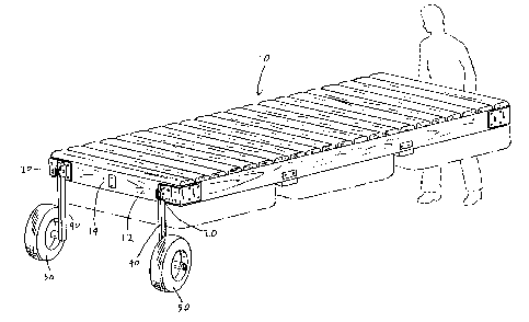
Fig. 1 is a perspective view of a dock embodying
the invention.
Fig. 2 is an enlarged perspective view
illustrating the connection between the base section,
clevis and wheel apparatus of the dock.
Fig. 3 is an exploded perspective view of a wheel
apparatus without the wheel attached.
Before one embodiment of the invention is
explained in detail, it is to be understood that the
invention is not limited in its application to the
details of construction and the arrangement of
components set forth in the following description or
illustrated in the drawings. The invention is capable
of other embodiments and of being practiced or being
carried out in various ways. Also, it is to be
understood that the phraseology and terminology used
herein is for the purpose of description and should not
be regarded as limiting.
DETAILED DESCRIPTION OF TI1E DRAWINGS
Shown in Fig. 1 of the drawings is a dock 10 for
use on or in a body of water. Typically, such docks
(or piers) are used to provide a platform upon which to
build a structure over the water or to provide a
structure at which to dock and disembark from
watercraft. Although the apparatus embodying the

CA 02270012 1999-04-22
-4-
invention is equally applicable to any kind of dock,
the dock shown in Fig. 1 is a floating dock.
The illustrated dock 10 includes a side portion 12
having a generally vertical surface 14, although it
should be understood that the dock 10 can be any
configuration which facilitates fabrication, assembly
and handling of the dock Z0. A pair of clevises 20 are
mounted on the surface 14. Each of the clevises 20 are
identical and accordingly only one of the clevises will
be described in detail.
Referring to Fig. 2, the clevis 20 includes a base
21 and a pair of tangs 32 extending outwardly from the
base 21. The clevis 20 is typically connected directly
to the surface 14 by some conventional means, or as
shown in Figs. 2 and 3, the base 21 of the clevis 20 is
connected by any known method (e. g., welding) to a base
portion 30 which is, in turn, connected to the surface
14 using screws, bolts or any other appropriate
connector. The tangs 32 are preferably substantially
parallel and extend perpendicular to the base 21,
although the clevis 20 can be in any configuration that
facilitates fabrication. The tangs 32 and the base
portion 30 also define a space 34 that is adapted to
receive wheel apparatus 40.
Figs. 2 and 3 illustrate one form of the wheel
apparatus 40 tliat is connected to the clevis 20 of the
dock 10. The wheel~apparatus 40 includes a vertical
support member 42, although it should be understood

CA 02270012 1999-04-22
-5-
that other types of support members could also be used.
The vertical support member 42 is sized to fit between
the tangs 32 of the clevis 20, and includes a through-
bore 46 that is axially aligned with the through-bores
34, 36 in the clevis 20. A locking pin 44 extends into
the through-bore 34 in one of the tangs 32, and then
into the through-bore 46 in the vertical support member
42, and finally into the through-bore 36 in the other
tang 32 in order to secure the vertical support member
42 to the dock 10. The locking pin is secured in place
using cotter pin 45 or some other known connector.
In alternative embodiments (not shown), a clevis
could be mounted on the wheel apparatus 40 and a tang
could extend from base portion 30 to fit into the
clevis on the wheel apparatus. The wheel apparatus
would still be secured in place using locking pin 44
and cotter pin 45.
The vertical support member 42 includes a lower
portion 38. An axle 39 is connected to the lower
portion 38 and defines an axis 48 (Fig. 2 only). As
shown in detail in Fig. 3, a wheel 50 is connected to
the axle 39 for rotation about the axis 48. The wheel
apparatus also includes a locking pin 60 extending
through the axle 39 to secure the wheel 50 to the axle
39.
The wheels 50 support the dock 10 for easy
movement across a lend surface (see Fig. 1).

CA 02270012 1999-04-22
~,
-6-
The clevises 20 can also be used to connect the
dock 10 to an additional dock section (not shown). The
additional dock section includes a second frame having
a generally vertical surface. A support member is
mounted on the surface and projects outwardly from a
side portion of the second frame. The support member
is dimensioned to fit between the tangs of the clevis
20. The support member includes a through-bore that is
aligned with the through-bores 34, 36 in the tangs 32.
A locking pin 44 extends through the through-bore of
one tang 34 in the clevis 32, through the through-bore
in the support member (not shown), and finally through
the through-bore 36 of the other tang 32 in order to
secure the dock 10 together with the additional dock
section.
Various other features and advantages of the
invention are set forth in the following claims.

Representative Drawing
A single figure which represents the drawing illustrating the invention.
Administrative Status

2024-08-01:As part of the Next Generation Patents (NGP) transition, the Canadian Patents Database (CPD) now contains a more detailed Event History, which replicates the Event Log of our new back-office solution.

Please note that "Inactive:" events refers to events no longer in use in our new back-office solution.

For a clearer understanding of the status of the application/patent presented on this page, the site Disclaimer , as well as the definitions for Patent , Event History , Maintenance Fee  and Payment History  should be consulted.

Event History

Description Date
Inactive: Expired (new Act pat) 2019-04-22
Change of Address or Method of Correspondence Request Received 2018-03-28
Inactive: Office letter 2007-02-27
Inactive: Corrective payment - s.78.6 Act 2007-01-22
Grant by Issuance 2005-10-25
Inactive: Cover page published 2005-10-24
Pre-grant 2005-08-15
Inactive: Final fee received 2005-08-15
Notice of Allowance is Issued 2005-06-14
Letter Sent 2005-06-14
Notice of Allowance is Issued 2005-06-14
Inactive: Approved for allowance (AFA) 2005-06-03
Amendment Received - Voluntary Amendment 2005-05-04
Inactive: S.29 Rules - Examiner requisition 2004-11-26
Inactive: S.30(2) Rules - Examiner requisition 2004-11-26
Amendment Received - Voluntary Amendment 2002-05-16
Letter Sent 2002-04-18
Request for Examination Requirements Determined Compliant 2002-03-20
All Requirements for Examination Determined Compliant 2002-03-20
Request for Examination Received 2002-03-20
Inactive: Entity size changed 2002-02-21
Inactive: Cover page published 1999-10-24
Application Published (Open to Public Inspection) 1999-10-24
Letter Sent 1999-09-23
Inactive: Single transfer 1999-08-27
Inactive: First IPC assigned 1999-06-11
Inactive: Courtesy letter - Evidence 1999-06-01
Inactive: Filing certificate - No RFE (English) 1999-05-28
Filing Requirements Determined Compliant 1999-05-28
Application Received - Regular National 1999-05-27

Abandonment History

There is no abandonment history.

Maintenance Fee

The last payment was received on 2005-03-31

Note : If the full payment has not been received on or before the date indicated, a further fee may be required which may be one of the following

  • the reinstatement fee;
  • the late payment fee; or
  • additional fee to reverse deemed expiry.

Please refer to the CIPO Patent Fees web page to see all current fee amounts.

Owners on Record

Note: Records showing the ownership history in alphabetical order.

Current Owners on Record
PLAYSTAR, INC.
Past Owners on Record
BRIAN K. ZEILINGER
Past Owners that do not appear in the "Owners on Record" listing will appear in other documentation within the application.
Documents

To view selected files, please enter reCAPTCHA code :


To view images, click a link in the Document Description column. To download the documents, select one or more checkboxes in the first column and then click the "Download Selected in PDF format (Zip Archive)" or the "Download Selected as Single PDF" button.

List of published and non-published patent-specific documents on the CPD .

If you have any difficulty accessing content, you can call the Client Service Centre at 1-866-997-1936 or send them an e-mail at CIPO Client Service Centre.


Document
Description 
Date
(yyyy-mm-dd) 
Number of pages   Size of Image (KB) 
Representative drawing 1999-10-15 1 14
Abstract 1999-04-22 1 11
Description 1999-04-22 6 205
Claims 1999-04-22 6 137
Drawings 1999-04-22 2 65
Cover Page 1999-10-15 1 31
Description 2005-05-04 6 202
Claims 2005-05-04 4 107
Representative drawing 2005-10-04 1 19
Cover Page 2005-10-04 1 40
Filing Certificate (English) 1999-05-28 1 165
Courtesy - Certificate of registration (related document(s)) 1999-09-23 1 139
Reminder of maintenance fee due 2000-12-27 1 112
Acknowledgement of Request for Examination 2002-04-18 1 180
Commissioner's Notice - Application Found Allowable 2005-06-14 1 160
Correspondence 1999-06-01 1 30
Correspondence 2005-08-15 1 30
Correspondence 2007-02-27 1 12