Language selection

Search

Patent 2270104 Summary

Third-party information liability

Some of the information on this Web page has been provided by external sources. The Government of Canada is not responsible for the accuracy, reliability or currency of the information supplied by external sources. Users wishing to rely upon this information should consult directly with the source of the information. Content provided by external sources is not subject to official languages, privacy and accessibility requirements.

Claims and Abstract availability

Any discrepancies in the text and image of the Claims and Abstract are due to differing posting times. Text of the Claims and Abstract are posted:

  • At the time the application is open to public inspection;
  • At the time of issue of the patent (grant).
(12) Patent Application: (11) CA 2270104
(54) English Title: INSTALLATION AND METHOD FOR REMOVING MERCURY FROM WASTE MATERIALS BY VACUUM DISTILLATION
(54) French Title: INSTALLATION ET PROCEDE D'ENLEVEMENT DE MERCURE A PARTIR DE DECHETS, PAR DISTILLATION SOUS VIDE
Status: Deemed Abandoned and Beyond the Period of Reinstatement - Pending Response to Notice of Disregarded Communication
Bibliographic Data
(51) International Patent Classification (IPC):
  • C22B 43/00 (2006.01)
  • B09C 1/06 (2006.01)
  • C22B 7/00 (2006.01)
  • F27B 5/04 (2006.01)
  • H01M 6/52 (2006.01)
(72) Inventors :
  • HAVERKAMP BEGEMANN, ROELAND
(73) Owners :
  • BEGEMANN HOLDING B.V.
(71) Applicants :
  • BEGEMANN HOLDING B.V.
(74) Agent: SMART & BIGGAR LP
(74) Associate agent:
(45) Issued:
(86) PCT Filing Date: 1997-11-19
(87) Open to Public Inspection: 1998-05-28
Examination requested: 1999-04-27
Availability of licence: N/A
Dedicated to the Public: N/A
(25) Language of filing: English

Patent Cooperation Treaty (PCT): Yes
(86) PCT Filing Number: PCT/NL1997/000630
(87) International Publication Number: WO 1998022628
(85) National Entry: 1999-04-27

(30) Application Priority Data:
Application No. Country/Territory Date
1004566 (Netherlands (Kingdom of the)) 1996-11-19

Abstracts

English Abstract


An installation for removing mercury from waste materials by vacuum
distillation comprises at least three electrically heatable, mobile,
hermetically sealable furnaces (1), which, in order to form a cluster, are
connected via a connecting line (3) and a cooling unit (4) to a distillation
vessel, which vessel (5) is connected to a vacuum pump (8). A standpipe (3)
with a mercury trap (6) is incorporated in each of the connecting lines
between the furnaces and the distillation vessel.


French Abstract

Cette installation d'enlèvement de mercure à partir de déchets, par distillation sous vide, comprend au moins trois fours mobiles, pouvant être chauffés électriquement et hermétiquement scellés (1) et qui, afin de former un groupe, sont reliés, via une canalisation de raccordement (3) et une unité de refroidissement (4), à une cuve de distillation (5), laquelle est elle-même reliée à une pompe à vide (8). On a incorporé une colonne montante (3) dotée d'un piège à mercure (6), dans chaque canalisation de raccordement entre les fours et la cuve de distillation.

Claims

Note: Claims are shown in the official language in which they were submitted.

5
claims
1. Installation for removing mercury from waste materials by vacuum
distillation,
comprising:
an electrically heatable heating device (1) in which waste material can be
exposed to
elevated temperature,
a cooling device (4) for cooling the vapour removed from said heating device
thereby
causing condensation of mercury,
a connection between said heating device and said cooling device,
collecting means (5) for collecting the liquid mercury flowing out the cooling
device,
and a vacuum pump (8) connected to the collecting vessel (5) via a suction
line (7,
10),
characterized is that the heating device consists of at least three mobile
furnaces (1)
arranged around the common cooling device and collecting vessel (5), each
furnace
(1) being provided at its top with a hermetically sealable lid (2) and being
non
rotatably connected to the cooling device (4) by a separate line (3)
debouching zero
the side wall of the concerning furnace (1).
2. Installation according to claim 1, characterized in that each line between
the
mobile furnace and the cooling unit includes a standpipe (3) having a mercury
trap
(6) in its lower part.
3. Installation according to claim 1 or 2, characterized in that the said
cooling unit
(4) consists of a heat exchanger which is mounted on the collecting vessel (5)
and
can be cooled with cooling water.
4. Installation according to claim 1 or Claim 2, characterized in that the
lids of the
furnaces (1) are pan- or dome-shaped and extend inwards into the furnaces (1).
5. Installation according to one of the preceding claims, characterized in
that a water
filter (9) is incorporated in the line (10) between the collecting vessel (5)
and the
vacuum pump (8).

6
6. Installation according to one of the preceding claim, characterized in that
an
oil/water separator (11) and one or more carbon filters (13) for the off-gases
are
connected in succession on the output side of the vacuum pump (8).

Description

Note: Descriptions are shown in the official language in which they were submitted.


ii;_ j . 1 O'.. : f 1'v - Q11 E:\!'f I1:\ f v~.' : I i- l - J!) : I : i : ( I
i :3 I 71J :3ry?7r'W(~i-~ -r'f!3 t3l l '?:3Sl.i~l 'lfi i : i~ :3
CA 02270104 1999-04-27
Title: Tnstatlation for removing mercury from waste materials by v'aaulm
distillation.
The invention relates to an installation for removing mercury from waste
rrtaterials by
vactlurn distillation, comprising:
S an elsoixic~llly heatable heating device in which waste material Can be
exposed to
elevated temperature,
a cooling device for cooling the vapour removed from said heating device
rhereby
causing condensation of mercury,
a connection between said heating device cad said cooling device,
eoilecting meows fc~r collecting the liquid mercury flowing out the cooling
device,
and a vacuum pump connected t~o the collecting vessel via a suction line.
Such au installation is disclosed in US~-A-5184950. A first embodiment,
described in
this publication, comprises an incliated rotatable ilarnace eonnerxed through
a rotay
~ oint try the cootm~co~~dcnsation device. A second embodiment comprises a
l~ori~on-
tal non rotatable fulrriace provided at its side with a lid.
'The aim of tho invention is to provide an installation with wluch the mercury
removal process can take place portir;'n by portion in harm~eic~lly scaled
chambers
2fl without it being possible for spnrious air containing mercury vapour to
pass inxo the
atmosphere.
According to the invention the instaii~ation is to this end characterized in
that the
heating dr~vice consists of at least three mobile, non rotatablo hermetically
sealable
furnaces axxanged around the common cooling device and collecting vessel,
cacti
furnace being connecting to the cooling de~c~ice by a separate line.
So as to be able to collect the mercury effectively, each line between a
mobile
furnace and the cooling devict includes a stand pipe having a mercury trap in
its
3p Lower part.
T'o prevent mercury cabdensizxg an the insa:de t~f the lids of the furnace,
said lids o~
be pan- ar dome-shaped anrl extend inwards into the furnace.

;..c : ~~.~~..i.; ,,-cu t-\c-ii!~:\ W v I:~- I -.y.~ : f:imitt ' .;i i~
:s.i?~~_':S-~ ti:~ B:i ~::i.r.i-i.i-f~:i:Fr 4
CA 02270104 1999-04-27
2
For further removal df subs#ances a water filter is incorporated in the line
between
the distillation vessel and the vacuum pump, and an oil/wata~t separation and
one cn
more carbon filters for the off--gases are connected in succession on the
onsput side
of the vaewm pump.
The method according to the invention can be carried out effectively and
rapidly 2nd
leads to a virtually mercury-fret ambient atmosphere. The porkion-try-portion
prc~eedure, such that tlfl spurious air can pass into the environment, is
important. The
cycle tir>ze is comphetely under control.
The invention will now be explained in mare detail with reference to the
figures.
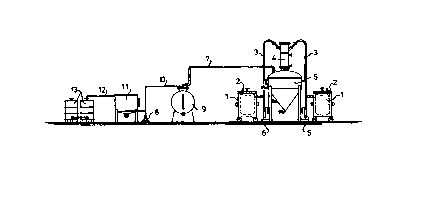
Figure 1 shows a side view of a mercury removal installation according to the
' ainvantion,
'h~gurc 2 shows a view of a fuznace to be used in said instalJ,ation.
Figure 3 shows a flatrr plan of the entire installation,
?,0 The installation shown in Figure 1 comprises a number of mobile furnaces
1, which
xre sealed with a lid 2 and in which raarcwy-adntaining waste (sludge,
complete
batteries, pulYerised fluorescent tubes, catalyst rnateri;al and tho li&e) is
present, The
fvrnaaes are each connected to their awu standpige 3, the top of which is
connected
to a common heat exchanger 4 which is cooled by cooling water and is mounted
?5 centrally ort a distillation vzssel 5. There is a connerxion between the
heat exchanger
and the instillation vessel. The bottom of the standpipes 3 Gorngrises a
mercury trap
6.
The distillation vessel is connected to a vacuum pump 8 via a suction line 7,
a water
30 filter 9 being ineorgorated in the suction line_ The. atmospheric pressure
side of the
suction purap 8 is connected by a line i0 to an oi.Uwater separator 11 and the
tatter,
in tarp, is connected via a Iiz~e 12 to a nur-nber of carbon f?lters 1,~.

!?C~1 . 1 ( ~'., : F.i' a '>It f.;',,t. l if '. ~:o : 3 p- 1 -~3Si : l ; :
t>t3 : :i L 7n :i i_.' i W'~i-. +-( '.1 Fj:l 'i:3:1;)-1- l E;: i ; a .;
CA 02270104 1999-04-27
The furnaces 2 (see Figure 2) hare an electrically heatahle casing 14 which is
insulated by s jac~ot consisring of, for example, mineral wool, T'hc
rexnoveblc lid 1S)
whirhh is able to seal the furnace hermetically, is in the shape df x pan or
dame
facing towards the inside of the furnace.
S
The wheels are indicated by ib and the connecting stub to tie connected to
standpipe
3 is indicated by 27. electric resistance wires, which are not shown, are
arranged in
the Casing 1~.
In the floor plan according to Figure 3 the mercury rc~rnoval installation
shown in
Figure Z is indic:atcd by A, the loading~unloading station by $ and the area
for
cooling the furnaces by C.
Drums 18 con:aiuing mexctuy-containing waste arc in the 3~ading~'Ltnlaading
stariot~
1 S B ready to 6e emptied by a ~ot~ile cram into relatively small fitrnaaes 1,
from which
the lids 2 have been carefully removed. After filling the furn~c;es with the
wash and
refitting the tins 2 to the furnaces, the furnaces I arc wheeled to a location
sraund a
distilia.tion vessel 5 and each furnace is connected by means of a standpipe 3
to the
heat exchanger ~t sa as to form a cluster.
~0
The vacuum pump 8 is sv~itehed on and the electric hating for the furnaces 1:
is then
switched dn_ A vacuum is generated in the furnac~cs as a result. If the waste
is waste
in sludge form Qr ground fluorescent tubes or Catalyst material, a vacuum of
at least
100 mbar and a temperature of at Least ~Ga ~C for example Q00 ~G~ arc required
to
ZS b aporise the mercur5.~ from the waste . Such a vacuum can be achieved u,~1
ng a so-
c~.llcd liquid ring pump. A vacuum of at least IQ mbar is needexl to remove
mercury
from non-ground ec~npletc batteries at the same temperature. In this case the
vacuum
pump 8 is supplen~euted by a so-called Roots pump.
30 The vapours from the furnaces 1 first pass into the relatively roQl
standpipes 3 where
a significant proportion of the mercwty condenses and fhws into the mercury
trap b,
from which it can be removed occasionally. The residual vapours are cooled in
the
heat exchanger 4, watwr, light and heavy aromatic compounds and residual
mercury

~C'\. V(>',.i~a'\ \11 t.\~ilf-.v ~~::: t-~- t -:l:l ; Via. m:-1 : :31 lm
a3o'~l:,~ti-y +I~i r;'a ::t~i:1~l9fs:> n f~
CA 02270104 1999-04-27
condensing and flowing into the distillation ~~essel. The liquids cart be
tapped off
fmut t5e-distillation vessel periodically and separatr,Iy, az various levels.
To prevent harmful gases passing into the ambient atawsphere, the gases
withdrawn
from the distillation vessel flow through, successively, the water filter 9,
the oillwater
separator 21 and the carbon filters 1,3. ~'urifird air can then be blown into
the
atmosphere without risk.
A dry, purified product remains behind in the furnaces 1. After being held for
some
time in the cooling tegifln C, the. furnaces arc wheeled back to the
loadi~g/unloading
station I3 and emptied. ThG dry, purified material is stored in containers I~,
It can be neon from the floor plan aeeordittg to Figure ~ that si:~c furnaces
with
standpipes 3 leave been placed in a circle azound the distillation vessel 5
and form a
IS cluster. ~f course, it is possible for various clusters of furnaces,
standpipes and
distillation vessels to be dealt with at the ,arae time and to be connected to
the same
i~lters 9, 13 and the separator 11,
'I''ae most important advantages of the installation deson'bed are:
- that the portietn-by~-portion treatment of the waste material lads to a
6ituation
in which no mercury-containing vapours such as sp~:rio~..s air can pass into
the
ambient atmosphere,
- that the cycle time is under control,
- thnt, despite the portion-by-portion treatment, the procedure can be carried
2S out very ef~cieritly and rapidly as a result t~f the u.se of relatively
.small mot~'tc
furnaces)
- that when a special vacuum pump is used mercury can be removed from intact
batteries.

Representative Drawing
A single figure which represents the drawing illustrating the invention.
Administrative Status

2024-08-01:As part of the Next Generation Patents (NGP) transition, the Canadian Patents Database (CPD) now contains a more detailed Event History, which replicates the Event Log of our new back-office solution.

Please note that "Inactive:" events refers to events no longer in use in our new back-office solution.

For a clearer understanding of the status of the application/patent presented on this page, the site Disclaimer , as well as the definitions for Patent , Event History , Maintenance Fee  and Payment History  should be consulted.

Event History

Description Date
Inactive: IPC removed 2013-02-21
Inactive: IPC assigned 2013-02-11
Inactive: IPC expired 2007-01-01
Inactive: IPC removed 2006-12-31
Inactive: IPC from MCD 2006-03-12
Inactive: Dead - No reply to s.30(2) Rules requisition 2003-10-02
Application Not Reinstated by Deadline 2003-10-02
Deemed Abandoned - Failure to Respond to Maintenance Fee Notice 2002-11-19
Inactive: Abandoned - No reply to s.30(2) Rules requisition 2002-10-02
Inactive: S.30(2) Rules - Examiner requisition 2002-04-02
Inactive: Cover page published 1999-07-19
Inactive: First IPC assigned 1999-06-14
Inactive: IPC assigned 1999-06-14
Inactive: Acknowledgment of national entry - RFE 1999-06-03
Letter Sent 1999-06-03
Application Received - PCT 1999-05-28
All Requirements for Examination Determined Compliant 1999-04-27
Request for Examination Requirements Determined Compliant 1999-04-27
Application Published (Open to Public Inspection) 1998-05-28

Abandonment History

Abandonment Date Reason Reinstatement Date
2002-11-19

Maintenance Fee

The last payment was received on 2001-11-07

Note : If the full payment has not been received on or before the date indicated, a further fee may be required which may be one of the following

  • the reinstatement fee;
  • the late payment fee; or
  • additional fee to reverse deemed expiry.

Please refer to the CIPO Patent Fees web page to see all current fee amounts.

Fee History

Fee Type Anniversary Year Due Date Paid Date
Request for examination - small 1999-04-27
MF (application, 2nd anniv.) - small 02 1999-11-19 1999-04-27
Basic national fee - small 1999-04-27
Registration of a document 1999-04-27
MF (application, 3rd anniv.) - small 03 2000-11-20 2000-11-09
MF (application, 4th anniv.) - small 04 2001-11-19 2001-11-07
Owners on Record

Note: Records showing the ownership history in alphabetical order.

Current Owners on Record
BEGEMANN HOLDING B.V.
Past Owners on Record
ROELAND HAVERKAMP BEGEMANN
Past Owners that do not appear in the "Owners on Record" listing will appear in other documentation within the application.
Documents

To view selected files, please enter reCAPTCHA code :


To view images, click a link in the Document Description column. To download the documents, select one or more checkboxes in the first column and then click the "Download Selected in PDF format (Zip Archive)" or the "Download Selected as Single PDF" button.

List of published and non-published patent-specific documents on the CPD .

If you have any difficulty accessing content, you can call the Client Service Centre at 1-866-997-1936 or send them an e-mail at CIPO Client Service Centre.


Document
Description 
Date
(yyyy-mm-dd) 
Number of pages   Size of Image (KB) 
Representative drawing 1999-07-19 1 5
Abstract 1999-04-27 1 52
Description 1999-04-27 4 187
Claims 1999-04-27 2 53
Drawings 1999-04-27 2 33
Cover Page 1999-07-19 1 41
Notice of National Entry 1999-06-03 1 203
Courtesy - Certificate of registration (related document(s)) 1999-06-03 1 116
Courtesy - Abandonment Letter (Maintenance Fee) 2002-12-17 1 176
Courtesy - Abandonment Letter (R30(2)) 2002-12-11 1 166
PCT 1999-04-27 18 624
Fees 2001-11-07 1 33
Fees 2000-11-09 1 32