Language selection

Search

Patent 2270152 Summary

Third-party information liability

Some of the information on this Web page has been provided by external sources. The Government of Canada is not responsible for the accuracy, reliability or currency of the information supplied by external sources. Users wishing to rely upon this information should consult directly with the source of the information. Content provided by external sources is not subject to official languages, privacy and accessibility requirements.

Claims and Abstract availability

Any discrepancies in the text and image of the Claims and Abstract are due to differing posting times. Text of the Claims and Abstract are posted:

  • At the time the application is open to public inspection;
  • At the time of issue of the patent (grant).
(12) Patent Application: (11) CA 2270152
(54) English Title: APPARATUS AND METHOD FOR REMOVING ENTRAINED LIQUID FROM GAS OR AIR
(54) French Title: DISPOSITIF ET PROCEDE SERVANT A SUPPRIMER DU LIQUIDE ENTRAINE DEPUIS DU GAZ OU DE L'AIR
Status: Deemed Abandoned and Beyond the Period of Reinstatement - Pending Response to Notice of Disregarded Communication
Bibliographic Data
(51) International Patent Classification (IPC):
  • B01D 46/30 (2006.01)
  • B01D 39/02 (2006.01)
  • B01D 53/26 (2006.01)
(72) Inventors :
  • PARKER, IAN S. (Canada)
  • MCKENZIE, ROBERT J. (Canada)
(73) Owners :
  • HYDRO PACIFIC TECHNOLOGIES INC.
(71) Applicants :
  • HYDRO PACIFIC TECHNOLOGIES INC. (Canada)
(74) Agent: NEXUS LAW GROUP LLP
(74) Associate agent:
(45) Issued:
(86) PCT Filing Date: 1997-02-14
(87) Open to Public Inspection: 1998-08-20
Examination requested: 1999-04-27
Availability of licence: N/A
Dedicated to the Public: N/A
(25) Language of filing: English

Patent Cooperation Treaty (PCT): Yes
(86) PCT Filing Number: 2270152/
(87) International Publication Number: CA1997000107
(85) National Entry: 1999-04-27

(30) Application Priority Data: None

Abstracts

English Abstract


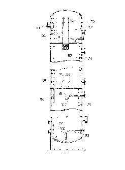
Apparatus for removing liquid entrained or dissolved in gas from the gas which
includes a distributor (82) located proximate an inlet region of a bed (74)
containing a network of channels bounded by solid material having sharp
protuberances, so as to cause the liquid entrained in the gas to condense, for
directing the gas through said bed (74). A collector (87), located proximate
an outlet region of said bed (74), is operative to collect the liquid that has
condensed in the bed (74) and to direct the gas which emerges from the bed
(74) away from the bed.


French Abstract

Dispositif servant à supprimer du liquide entraîné ou dissous dans du gaz depuis ce gaz et comprenant un distributeur (82) situé à proximité d'une zone d'entrée d'un lit (74) contenant un réseau de canaux limités par un matériau solide présentant des protubérances aiguës, de manière à provoquer la condensation du liquide entraîné dans le gaz, servant à diriger le gaz à travers ledit lit (74). Un collecteur (87) situé à proximité d'une zone de sortie dudit lit (74) sert à recueillir le liquide s'étant condensé dans le dit (74) et à diriger le gaz émergeant du lit (74) afin qu'il s'éloigne de ce dernier.

Claims

Note: Claims are shown in the official language in which they were submitted.


6
We Claim:
1. Apparatus for removing liquid entrained and dissolved in
gas from the gas, said apparatus having a housing (70) with a gas inlet (78),
a gas outlet (90) and a fluid outlet (92), comprising:
(a) a distributor (82) located proximate said gas inlet (78);
(b) a bed (74) in said housing (70) containing a network of
channels bounded by non-porous solid material having sharp
protuberances, so as to cause the liquid entrained and dissolved in the gas
to condense, said distributor (82) operative to disperse gas coming from
said gas inlet (78) over an inlet end of said bed (74);
(c) a collector (87) located proximate an outlet region of
said bed (74) operative to collect the liquid that has condensed in said bed
and direct the gas which emerges from said bed (74) away from said bed to
said gas outlet (90).
2. Apparatus according to claim 1, wherein said non-porous
solid material is formed by particulates.
3. Apparatus according to claim 1, wherein said non-porous
solid material is gravel.
4. Apparatus according to claim 1, wherein said non-porous
solid material is gravel mixed with sand.
5. Apparatus according to claim 1, wherein said distributor (82)
is a plate having an array of holes through which the gas may pass so as to
distribute the gas over substantially the entire cross-sectional area of the
bed (74).

7
6. Apparatus according to claim 1, wherein the collector (87) is
located so that gravitational force is applied to said liquid so as to cause
it
to move in a direction away from the flow of said gas entering said gas
outlet (90).
7. Apparatus according to claim 1, wherein said housing (70)
has a gas inlet chamber (72) and a gas outlet chamber (76) wherein said gas
inlet (78) is located in said gas inlet chamber (72) for admitting gas therein
and said gas outlet (90) is located in said gas outlet chamber for conducting
gas therefrom.
8. Apparatus according to claim 7, wherein said housing (70) is
cylindrical.
9. Apparatus according to claim 8, wherein an axis of said
housing is horizontal and said collector (87) is located vertically below said
bed (74) when said apparatus is in operation.
10. A method of removing liquid entrained and dissolved in gas
from the gas, comprising:
(a) directing said gas through a bed (74) containing a
network of channels bounded by non-porous solid material having sharp
protuberances which cause the liquid entrained and dissolved in the gas to
condense without absorbing the liquid; and
(b) collecting the liquid that has condensed and directing
the gas which emerges from the bed (74) away from the bed.
11. A method according to claim 10, wherein the non-porous
solid material is formed by particulates.

8
12. A method according to claim 10, wherein the non-porous
solid material is gravel.
13. A method according to claim 10, wherein the non-porous
solid material is gravel and sand.
14. A method according to claim 10, including a distributor
mounted at an inlet to said bed to distribute said gas over said inlet region.
15. A method according to claim 10, including a collector near an
outlet from said bed positioned to collect liquid condensed in said bed.

Description

Note: Descriptions are shown in the official language in which they were submitted.


CA 02270152 1999-04-27
.,. ..,
. a
. . " ".. .. ..
APPARATUS AND METHOD FOR REMOVING ENTRAINED
AND DISSOLVED LIQUID FROM GAS OR AIR
FIELD
The present invention relates to an apparatus and method for
removing entrained and dissolved liquid from gas or air.
BACKGROUND
It is known in the art to pass gas through a filter bed so as to
remove suspended impurities. However, the accumulation of impurities
in the filter bed tends to clog the bed and inhibit further gas flow.
Moreover, moisture trapped in the gas tends not to precipitate in the filter
bed. Filter beds of desiccant materials such as silica gel or calcium chloride
have been used as in U.S. Patent No. 3,465,503 issued to Henderson and
U.S. Patent No. 913,325 issued to Touzimsky. In the latter Patent the
airflow is around the outside of a central cylinder of the desiccant bed.
Materials such as fibre glass and steel mesh are known for use
in removing entrained but not dissolved liquid from a gas stream. U.S.
Patent No. 5,061,300 issued to Alexander, III describes a coalesces filter
which removes liquid from air. It relies on air passing first upwardly
through a fibrous metallic coalescing material, and then downwardly
through a filter material.
Canadian Patent No. 1,125,671 issued to John R. McKenzie
discloses an apparatus for filtering moisture and impurities from natural
gas utilizing a gravel bed as a filter and a series of metal baffle plates to
inhibit gas flow. Gravel particles greater than one inch are used. The bed
is such that only filtering is accomplished without any reduction in the
dew point. Thus, dissolved liquid in the gas is not removed leaving
significant moisture still in the gas.
- . ~ ..n.:. _ _ -~l.r~~

CA 02270152 1999-04-27
. ,_.
~ ~ 9 s i ~ v
~ v
~~ ~ sv
It is an object of the present invention to provide an
improved method and apparatus for removing liquid entrained and
dissolved in gas from the gas.
SUMMARY OF THE INVENTION
According to the invention there is provided apparatus for
removing liquid entrained or dissolved in gas from the gas. The apparatus
includes a distributor located proximate an inlet region of a bed containing
a network of channels bounded by non-porous solid material having
sharp protuberances so as to cause the liquid to condense. Further
included is a collector located proximate an outlet region of the bed
operative to collect the liquid that has condensed in the bed and direct the
gas which emerges from the bed away from the bed. Prior efforts have
removed the mist or non-dissolved moisture in air but not the dissolved
moisture. As a result the present apparatus causes a reduction in the dew
point of the gas that passes through the device.
The non-porous solid material may be formed by particulates
and may, in fact, be gravel. A further refinement which increases liquid
extraction efficiency is to mix sand with the gravel.
The means for directing may be a plate having an array of
holes through which the gas may pass so as to distribute the gas over
substantially the entire cross-sectional area of the bed.
The means for collecting may include means for applying
gravitational force to the liquid so as to cause it to move in a direction
away from the flow of the gas.
Preferably the apparatus may include a housing having an
inlet chamber, a filter chamber and an outlet chamber. The inlet chamber
r1 ~7jt~TT

CA 02270152 1999-04-27
.,
. ", .. ..
may have a gas port for admitting gas therein and a distributor at an input
end of the bed for distributing the gas over a cross-sectional area of the
bed.
Advantageously the housing may be a cylindrical tank.
In another aspect of the invention there is provided a
method of removing liquid entrained or dissolved in gas from the gas
which includes directing the gas through a bed containing a network of
channels bounded by non-porous solid material having sharp
protuberances which cause the liquid entrained in the gas to condense, and
collecting the liquid that has condensed and directing the gas which
emerges from the bed away from the bed.
BRIEF DESCRIPTION OF THE DRAWINGS
The novel features believed characteristic of the invention
are set forth in the appended claims. The invention itself, however, as
well as other features and advantages thereof, will be best understood by
reference to the detailed description which follows, read in conjunction
with the accompanying drawing, wherein:
Fig. 1 is a cross-sectional view in elevation of a vertical
arrangement.
DETAILED DESCRIPTION WITH REFERENCE TO THE DRAWING
Referring to Figure 1, a vertical orientation of an apparatus
for separating liquids from gases and air is shown in which cylindrical
tank 70 has three regions. The first region is an inlet chamber 72 separated
by a plate 71 from a second region which is a filter section 74. Filter
section
74 is separated by a plate 81 from a third region which is an outlet chamber
76. Inlet pipe 78 forms a passageway for gas or air into the inlet chamber
72. Pipe 80 having an inlet near a closed end of the inlet chamber 72
provides fluid communication between the latter chamber and the filter
section 74 through a plurality of 1/2 inch holes 82 spaced one inch apart at
.: , _
~i.r-~.

CA 02270152 1999-04-27
7 ~ y 1 ' 1 1 1
,'
.. .) , , ., ..
the other end of pipe 80. Filter section 74 is filled with a gravel bed with
gravel particles in the range of 1 /4 inch in diameter mixed with sand. The
amount of sand may vary from being negligible to any desired amount
that may be selected to give a required drying efficiency as balanced against
allowed inlet to outlet pressure drop. Plate 81 has a vcentral portion with
an array of 1/2 inch holes 84 therethrough, and an annular array of holes
86 around the outside. Beneath the outside holes is a tubular baffle 88
which extends into the outlet chamber 76. A collector 87 at the bottom of
outlet chamber 76 collects condensed liquid. A pipe 91 near the top of the
outlet chamber 76 provides for the exit of gas while near the bottom is a
pipe 92 designed as a passageway for separated liquid.
In this case gas or air enters pipe 78, fills inlet chamber 72 and
enters at the top of pipe 80. Typically the pressure in chamber 72 is in the
region of 800 to 1200 psi. The gas then passes through holes 82 into the
gravel bed in filter section 74. As a result of passing over sharp-edged
regions of the granules, the entrained and dissolved liquid in the gas
condenses and flows to the outside and downwardly. The liquid passes
through holes 86 and into the bottom of outlet chamber 76 where it flows
out pipe 92 upon reaching the level of the outlet nozzle 93. Clean gas
which emerges through holes 84 exits through outlet port 90 of pipe 91
with very little pressure drop from the pressure in the inlet chamber 72.
Moreover, after passing through the apparatus the dew point of the gas is
lowered indicating that entrained and dissolved liquid is being removed
from the gas.
It has been found that the efficiency of liquid separation from
gas is directly dependent on the amount of sand contained in the gravel
bed. For example, with natural gas, sand lowers the moisture content of
the gas from 7 pounds per million cubic feet which is obtained with no
sand to under 2 pounds per million cubic feet which is obtained with a
significant amount of sand.
_. -;::__ .. :-r

CA 02270152 1999-04-27
..,
, v
~. ~ sv
While gravel and sand have been found to work well in
separating liquid from gas, other types of arrangements may be used. For
example, drilled nozzle plates or multiple or single orifice devices may be
used. Similarly, particles of broken glass with fines Or any other granular
material could be used, whether the structure of the particles is ordered or
disordered. Materials that work less well would include porous materials
such as lava rock. T'he important thing is that the bed contains a network
of channels bounded by non-porous solid material having sharp
protuberances. No significant cooling of the gas from inlet to outlet is
required to achieve condensation.
While gravity separation of condensed liquids has been
disclosed in each of the embodiments described above, cyclone or velocity
separation systems could be used.
In the present embodiments particle sizes of the order of 1/4
inch have been described. However, the preferred size range depends
upon the gas flow rates.
Accordingly, while this invention has been described with
reference to illustrative embodiments, this description is not intended to
be construed in a limiting sense. Various modifications of the illustrative
embodiments, as well as other embodiments of the invention, will be
apparent to persons skilled in the art upon reference to this description. It
is therefore contemplated that the appended claims will cover any such
modifications or embodiments as fall within the true scope of the
invention.
,..,_.,

Representative Drawing
A single figure which represents the drawing illustrating the invention.
Administrative Status

2024-08-01:As part of the Next Generation Patents (NGP) transition, the Canadian Patents Database (CPD) now contains a more detailed Event History, which replicates the Event Log of our new back-office solution.

Please note that "Inactive:" events refers to events no longer in use in our new back-office solution.

For a clearer understanding of the status of the application/patent presented on this page, the site Disclaimer , as well as the definitions for Patent , Event History , Maintenance Fee  and Payment History  should be consulted.

Event History

Description Date
Inactive: Agents merged 2011-07-06
Application Not Reinstated by Deadline 2001-02-14
Time Limit for Reversal Expired 2001-02-14
Deemed Abandoned - Failure to Respond to Maintenance Fee Notice 2000-02-14
Inactive: Office letter 2000-01-19
Inactive: Protest/prior art received 1999-09-15
Inactive: Cover page published 1999-07-13
Inactive: IPC assigned 1999-06-15
Inactive: First IPC assigned 1999-06-15
Inactive: IPC assigned 1999-06-15
Inactive: Acknowledgment of national entry - RFE 1999-05-31
Letter Sent 1999-05-31
Application Received - PCT 1999-05-28
Request for Examination Requirements Determined Compliant 1999-04-27
All Requirements for Examination Determined Compliant 1999-04-27
Application Published (Open to Public Inspection) 1998-08-20

Abandonment History

Abandonment Date Reason Reinstatement Date
2000-02-14

Maintenance Fee

The last payment was received on 1999-04-27

Note : If the full payment has not been received on or before the date indicated, a further fee may be required which may be one of the following

  • the reinstatement fee;
  • the late payment fee; or
  • additional fee to reverse deemed expiry.

Patent fees are adjusted on the 1st of January every year. The amounts above are the current amounts if received by December 31 of the current year.
Please refer to the CIPO Patent Fees web page to see all current fee amounts.

Fee History

Fee Type Anniversary Year Due Date Paid Date
MF (application, 2nd anniv.) - small 02 1999-02-15 1999-04-27
Registration of a document 1999-04-27
Basic national fee - small 1999-04-27
Request for examination - small 1999-04-27
Owners on Record

Note: Records showing the ownership history in alphabetical order.

Current Owners on Record
HYDRO PACIFIC TECHNOLOGIES INC.
Past Owners on Record
IAN S. PARKER
ROBERT J. MCKENZIE
Past Owners that do not appear in the "Owners on Record" listing will appear in other documentation within the application.
Documents

To view selected files, please enter reCAPTCHA code :


To view images, click a link in the Document Description column. To download the documents, select one or more checkboxes in the first column and then click the "Download Selected in PDF format (Zip Archive)" or the "Download Selected as Single PDF" button.

List of published and non-published patent-specific documents on the CPD .

If you have any difficulty accessing content, you can call the Client Service Centre at 1-866-997-1936 or send them an e-mail at CIPO Client Service Centre.


Document
Description 
Date
(yyyy-mm-dd) 
Number of pages   Size of Image (KB) 
Description 1999-04-26 5 227
Claims 1999-04-26 3 87
Abstract 1999-04-26 1 55
Drawings 1999-04-26 1 28
Representative drawing 1999-07-06 1 9
Notice of National Entry 1999-05-30 1 203
Courtesy - Certificate of registration (related document(s)) 1999-05-30 1 116
Courtesy - Abandonment Letter (Maintenance Fee) 2000-03-12 1 183
PCT 1999-04-26 23 803
Correspondence 2000-01-18 1 7
Correspondence 2000-01-18 1 8