Language selection

Search

Patent 2270299 Summary

Third-party information liability

Some of the information on this Web page has been provided by external sources. The Government of Canada is not responsible for the accuracy, reliability or currency of the information supplied by external sources. Users wishing to rely upon this information should consult directly with the source of the information. Content provided by external sources is not subject to official languages, privacy and accessibility requirements.

Claims and Abstract availability

Any discrepancies in the text and image of the Claims and Abstract are due to differing posting times. Text of the Claims and Abstract are posted:

  • At the time the application is open to public inspection;
  • At the time of issue of the patent (grant).
(12) Patent Application: (11) CA 2270299
(54) English Title: RAIL RETAINING DEVICE
(54) French Title: DISPOSITIF DE RETENTION DE RAIL
Status: Deemed Abandoned and Beyond the Period of Reinstatement - Pending Response to Notice of Disregarded Communication
Bibliographic Data
(51) International Patent Classification (IPC):
  • E01B 9/34 (2006.01)
  • E01B 3/16 (2006.01)
  • E01B 9/30 (2006.01)
  • E01B 9/48 (2006.01)
(72) Inventors :
  • IGWEMEZIE, JUDE (Canada)
(73) Owners :
  • JUDE IGWEMEZIE
(71) Applicants :
  • JUDE IGWEMEZIE (Canada)
(74) Agent: SMART & BIGGAR LP
(74) Associate agent:
(45) Issued:
(22) Filed Date: 1998-10-14
(41) Open to Public Inspection: 2000-04-14
Availability of licence: N/A
Dedicated to the Public: N/A
(25) Language of filing: English

Patent Cooperation Treaty (PCT): No

(30) Application Priority Data: None

Abstracts

Sorry, the abstracts for patent document number 2270299 were not found.

Claims

Note: Claims are shown in the official language in which they were submitted.
Sorry, the claims for patent document number 2270299 were not found.
Text is not available for all patent documents. The current dates of coverage are on the Currency of Information  page

Description

Note: Descriptions are shown in the official language in which they were submitted.


CA 02270299 1999-04-08
- 1 -
Rail Retainina Device
The present invention relates to rail retaining
devices for incorporation in a rail track.
The invention provides a rail retaining device for
use with shoulder members for engaging opposite lateral
sides of a rail flange, in the form of a rail clip to be
associated with each shoulder member in the form of a
bent rod symmetrical about a vertical plane for extending
laterally of the rail and having an inner portion for
bearing on the adjacent flange, intermediate limb
portions for bearing upwardly on a downwardly facing
abutment surface provided on the shoulder member and an
outer portion connected to each intermediate limb portion
and extending outwardly from said abutment surface and
curving laterally arcuately outwardly and downwardly
toward a lower portion adapted to bear on a bearing
surface, preferably at a region offset laterally inwardly
from a centre of curvature of said outer portion.
The clip is compliant and tolerant of dimensional
variation in the components and is,relatively easily to
install, while providing a highly effective and durable
rail retaining function.
In a preferred form, the inner portion comprises an
upwardly bowed portion adjacent the abutment surface that
provides increased resistance to migration of the clip
outwardly from its installed position as a result of
impacts or vibration encountered in service.
Preferably, each lower portion of said outer
portions inclines longitudinally with respect to said
vertical plane, whereby squatting of the outer portion is
facilitated during installation, rendering the clip
particularly compliant and facilitating installation.

CA 02270299 1999-04-08
- 2 -
Examples are described in more detail hereinafter,
by way of example, with reference to the accompanying
drawings.
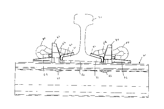
Figs. 1, 2 and 3 show side, top and isometric views
of installed rail retaining devices in accordance with a
first embodiment of the present invention.
Figs. 4, 5, 6, 7 and 8 show front isometric, rear
isometric, top, side and front views, respectively of .the
clip employed in the arrangements of Figs. 1 to 3.
Figs. 9, 10, 11 and 12 show top, isometric, side and
front views of a second embodiment of a rail clip in
accordance with the invention.
Figs. 13, 14, 15 and 16 show isometric, rear, top,
side and back front views, respectively of a third
embodiment of the rail clip.
Referring to the drawings, wherein like reference
numerals indicate like parts, Figs. 1 to 3 show a
fastening arrangement employing a steel tie 20, cant
plate 50 and hook-in field and gauge shoulder members 60
and 70, respectively, generally as and installed as
described in applicant's published application WO
96/23107, which should be referred to for further
details.
In the installed position, as seen in Figs. 1 to 3,
clips 80 extend through openings 61 and 71 in the
shoulder members 60 and 70, respectively, and bear
upwardly on an upper side of the opening 61 or 71. An
inner end of the clip 80, with respect to a rail 30 bears
on a rail flange 31 or on an electrical insulator pad 90
interposed between the rail flange 31 on the one hand and
the clip 80 and the shoulder 60 or 70 on the other.

CA 02270299 1999-04-08
- 3 -
A laterally outer end of the clip 80 engages on a
laterally outer extension 62 or 72 of the shoulder 60 or
70.
Also visible in Fig. 1 are the hook-in leg portions
63 and 73 that are passed through openings in the tie 20
and secure the shoulder portions 60 and 70, respectively,
to the tie 20.
As seen in more detail in Figs. 4 to 8, the clip 80
is of bent rod symmetrical about a vertical plane 81,
seen in Fig. 2, extending laterally of the rail 30 with
an inner portion 82 bearing on the rail flange,
intermediate limb portions 83 bearing upwardly on
downwardly facing abutment portion 61, and an outer
portion 84 curving laterally arcuately outwardly and
downwardly and bearing on a bearing surface.
An upwardly bowed portion 86 provides increased
resistance to migration of the clip 80 outwardly.
The outer portions 87 are toed inwardly. During
installation the clip 80 compresses or squats and is
easily installed.
Uplift of the flange 31 is resisted by bending
resistance of the installed clip 80 between portions 83
at 84 and by torsional resistance.
The clip 80 has excellent stress distribution
properties.
Clip 100 shown in Figs. 9 to 12 and 12 is similar to
clip 8 except portions 107 are toed outwardly.
Clip 110 shown in Figs. 13 to 16 is similar to clip
100 except end portions 108 extend upwardly and abut the

CA 02270299 1999-04-08
- 4 -
outer side of the shoulder such as shoulder 60 in the
installed position.

Representative Drawing
A single figure which represents the drawing illustrating the invention.
Administrative Status

2024-08-01:As part of the Next Generation Patents (NGP) transition, the Canadian Patents Database (CPD) now contains a more detailed Event History, which replicates the Event Log of our new back-office solution.

Please note that "Inactive:" events refers to events no longer in use in our new back-office solution.

For a clearer understanding of the status of the application/patent presented on this page, the site Disclaimer , as well as the definitions for Patent , Event History , Maintenance Fee  and Payment History  should be consulted.

Event History

Description Date
Inactive: IPC from MCD 2006-03-12
Application Not Reinstated by Deadline 2001-10-05
Inactive: Dead - Application incomplete 2001-10-05
Deemed Abandoned - Failure to Respond to Maintenance Fee Notice 2000-10-16
Deemed Abandoned - Failure to Respond to Notice Requiring a Translation 2000-10-05
Inactive: Incomplete 2000-07-05
Application Published (Open to Public Inspection) 2000-04-14
Inactive: Cover page published 2000-04-13
Inactive: First IPC assigned 1999-06-18
Application Received - Regular National 1999-05-31
Filing Requirements Determined Compliant 1999-05-31
Inactive: Filing certificate - No RFE (English) 1999-05-31

Abandonment History

Abandonment Date Reason Reinstatement Date
2000-10-16
2000-10-05

Fee History

Fee Type Anniversary Year Due Date Paid Date
Application fee - small 1998-10-14
Owners on Record

Note: Records showing the ownership history in alphabetical order.

Current Owners on Record
JUDE IGWEMEZIE
Past Owners on Record
None
Past Owners that do not appear in the "Owners on Record" listing will appear in other documentation within the application.
Documents

To view selected files, please enter reCAPTCHA code :


To view images, click a link in the Document Description column. To download the documents, select one or more checkboxes in the first column and then click the "Download Selected in PDF format (Zip Archive)" or the "Download Selected as Single PDF" button.

List of published and non-published patent-specific documents on the CPD .

If you have any difficulty accessing content, you can call the Client Service Centre at 1-866-997-1936 or send them an e-mail at CIPO Client Service Centre.


Document
Description 
Date
(yyyy-mm-dd) 
Number of pages   Size of Image (KB) 
Abstract 2000-04-14 1 2
Claims 2000-04-14 1 2
Cover Page 2000-04-07 1 21
Description 1999-04-08 4 124
Drawings 1999-04-08 7 144
Representative drawing 2000-04-07 1 10
Filing Certificate (English) 1999-05-31 1 165
Reminder of maintenance fee due 2000-06-15 1 109
Courtesy - Abandonment Letter (incomplete) 2000-10-26 1 171
Courtesy - Abandonment Letter (Maintenance Fee) 2000-11-14 1 183
Correspondence 2000-07-05 1 11
Correspondence 1999-06-01 1 21