Note: Descriptions are shown in the official language in which they were submitted.
CA 02270547 1999-04-30
WO 98I19028 PCT/iJS97/19620
Load-Bearing Bale Building System
Background--Field of invention
This invention is intended for use in the field of building construction,
specifically, straw bale construction. It represents an improved system of
construction that utilizes custom-sized bales having integral structural
supports.
Background--Brief description of the prior art
Straw bale construction is environmentally, economically, and esthetically
superior to other contemporary construction techniques. Straw, which in many
areas is an agricultural waste product, is ideal for use as a building
material
because it has low embodied energy and yet gives the wall of the structure a
high
thermal energy efficiency because of its excellent insulating qualities. The
techniques of straw bale construction in current use, however, are antiquated;
they
consist basically of two techniques that date back more than 100 years.
The first technique uses the bales to bear the loads of the roof, snow, and
wind. Because of the variations in stress as snow loads and winds change, the
interior and exterior plaster and stucco finishes are prone to cracking. Orr
(U.S. Pat.
2o No. 312,375) discloses a variation of this system in which long bolts are
used to
compress the bales and maintain them in a compressed state, which alleviates
the
problem with plaster cracking. However, this method is not approved by
building
codes in many areas. Its major drawback is that it is highly labor-intensive:
each
individual bate must be stacked, plumbed, and pinned in place; and the
multiple
layers of small bales must be stacked Pike bricks in an overlapping, break
joint
fashion, which means that every other bale must be retied and then cut to size
wherever there is a corner, a door, a post, a window, etc. The many joints and
layers produced by this process result in numerous gaps, so that up to three
times
as much plaster and stucco (and, hence, labor) is needed to produce a smooth,
flat
CA 02270547 1999-04-30
WO 98/19028 PCT/US97/19620
_2_
wall finish as in conventional frame construction. In addition, the joints and
gaps
reduce the energy efficiency and the fire resistance of the house.
The second technique uses posts that extend from the footing to the roof and
are connected at the top by beams to support the roof. Straw bales are then
stacked between the posts to provide insulation and a surtace for finishing.
This
technique, like the first, is labor-consuming: each course of bales must be
anchored
to the post structure, and the top course must be anchored to the beam at
least
every 24 inches. In addition, this technique requires large-dimension lumber
or
1o steel for the post-and-beam frame. The high cost of large-dimension lumber
and
steel has in many cases led builders to install windows in the walls without
using
support posts on the sides of the windows. Instead, they merely pin the rough
bucks for the windows to the adjacent bales with wooden dowels. This produces
a
poorly supported window that is prone to cause cracks in the plaster and
stucco
~5 surrounding it.
Both of the current straw bale construction techniques require, further, that
the electrical wiring and communication cables be pushed between the bales to
the
proper depth to meet code requirements. This is labor-intensive and difficult,
2o particularly with very dense bales. Specialized systems, such as central
vacuum
cleaners, are practically impossible to install in conventional straw bale
walls
because of the diameter of the piping.
Other prior art includes Hewlett (US Pat. No. 1,604,097}, who discloses a
25 system that employs plaster and fiber blocks through which concrete pillars
are
poured for structural support. This system is also labor-intensive: the many
courses of blocks must be laid by hand and then the concrete pillars must be
poured. Hewlett acknowledges that this system is very difficult to use on dry,
compressed fibrous material such as straw bales, because the concrete dries
3o prematurely.
Chauvin et al. (France Pat. No. 1.525.387) disclose a bale of slaked-lime
coated straw with an outer shell that is a mixture of Portland cement and
straw.
CA 02270547 1999-04-30
WO 98l19028 PCT/US97119620
-3-
These bales are not complete wall segments, do not have integral structural
supports, and would have the same problem as the Hewlett system with premature
drying and lack of hydration of the cement.
In another area of search, Brown (US Pat. No. 169,518), Archer (US Pat.
No. 181,389), Ackerman (US Pat. N. 183,617)) and Ingersoll (US Pat. No.
185,106)
all disclose bales of short-cut hay or manure held together with boards or
sticks. In
these cases, the bales are not intended for use in construction, the boards or
sticks
are merely packaging for the material being baled.
0
Finally, Huguet (US Pat. No. 4,154,030) discloses another system that uses
posts and beams as the load-bearing members of a rigid building form. Non-load-
bearing panels, prefabricated of recycled waste materials, span the openings
of the
form. Problems with this system include the potential for toxicity, from the
waste
~5 materials that are molded to form the panels and/or the polymers or other
carrier
that bind them together, and the increased embodied energy of construction. In
addition) although this system uses U channels as a tie beam, screws or bolts
are
still needed to hold the elements together.
2o Objects and Advantages
Accordingly, several objects and advantages of my invention are that it:
(a) enables very rapid construction of walls; in most cases, the walls and
roof of
a house can be erected in one day, owing to both the large size of the bales
and
the snap-together footing connection.
(b) reduces both on-site-and off-site framing labor.
(c) reduces labor required for placement of electrical wiring, junction boxes,
communication cables, and central vacuum cleaner piping, because precut or
.3o formed grooves are provided for these.
CA 02270547 1999-04-30
WO 98I19028 PCT/US97/19620
-4-
(d) reduces labor for installing windows and doors because support framing for
these are adjacent to all openings as an integral part of the load-bearing
bale.
(e) reduces labor needed to achieve smooth stucco and plaster finishes by
reducing the number of joints and gaps in the walls.
(f) reduces costs, both economic and environmental, by using renewable
agricultural waste products as the major building material without using
chemical or
heat treatments (which increase embodied energy and, thus, cost), to bind the
o fibers together.
(g) reduces costs, both economic and environmental, by using much less steel
and/or large-dimension lumber. The bale ties, compressed straw, and structural
supports create a synergistic package; because the compressed straw serves as
a
brace for the structural supports, the thickness of the supports can be
reduced.
(h) reduces costs by using less stucco and plaster than conventional straw
bale
construction because there are fewer gaps and joints to fill.
(i) improves the already superior fire resistance of plastered straw bale
construction by reducing the number of joints and gaps in the walls.
(j) increases thermal efficiency by reducing the number of joints and gaps in
the
walls.
(k) offers excellent protection against stresses, such as strong winds and
earthquakes, because the roof-to-footing tie is much stronger than nailing.
(1) provides a means of fabricating large beams or posts using less steel or
3o wood.
CA 02270547 1999-04-30
WO 98I19028 PCT/US97119620
(m) provides a way to use a variety of structural materials in combinations
that
best exploit the unique physical properties of each.
Further objects and advantages will become apparent from the summary and
the description of the figures that follow.
Figures
Fig. 1 shows a perspective view of the currently preferred embodiment, for
walls, of a load-bearing bale.
1o Fig. 2 shows an exploded end view of a load-bearing bale.
Fig. 3 shows a detail view of the inverted-lip U channel.
Fig. 4 shows a detail view of one embodiment of the connection between an
inverted-lip U channel and a structural support.
Fig. 5 shows a perspective view of two wall segments and one window
~5 segment.
Fig. 6 shows a perspective view of second embodiment of a load-bearing
bale with structural supports on both side surfaces.
Fig. 7 shows a perspective view of third embodiment of a load-bearing bale
with structural supports having tabs at the bottom, for connecting the
structural
2o supports to the footing, and an angle iron bond beam at the top.
Fig. 8 shows an exploded end view of a load-bearing bale in which an
anchor-shaped structural connector on the footing snaps into an arrow-shaped
opening in the structural support.
Fig. 9 shows an exploded end view of a load-bearing bale with a serrated
25 slot in the structural support that receives the anchor-shaped connector.
Fig. 10 shows two different embodiments of the connection between an
inverted-lip U channel and a wooden structural support.
Fig. 11 shows a wooden structural support with multiple wire cinctures on
each end and the inverted-lip U channel.
so Fig. 12 shows an inverted-lip U channel with pre-punched tabs for attaching
trusses.
CA 02270547 1999-04-30
WO 98/19028 PCT/US97/19620
-6-
Fig. 13 shows a perspective view of a flat-roofed building. The walls and
parapet use the load-bearing bales of Fig. 1; the roof utilizes the load-
bearing bales
of Fig. 6, sandwiched between I-shaped-flat-roof trusses.
Fig. 14 is a cross-section view of the roof structure in Fig. 13.
Fig. 15 shows a load-bearing bale in the configuration of a post or beam.
Fig. 16 shows a load-bearing bale in the configuration of a post or beam with
an expanded metal shell.
Fig. 17 shows an end view of a load-bearing-bale postlbeam using only an
expanded metal shell for structural support.
1o Fig. 18 show a perspective view of a different embodiment of the load-
bearing bale to inverted-lip U channel which uses a metal bar for the
connection.
Reference
Numerals
in Drawings
load-bearing bale 11 end surface -
~5 12 end surface 13 side surface
14 side surtace 16 upper surtace
18 lower surface 20 structural support
22 cincture 24 groove
26 bale tie in bottom of groove 28 inverted-lip U channel
30 slot 34 footing
36 U-channel splice 38 U-channel corner splice
40 banding 41 window sill frame
42 window opening 43 window header
44 concrete fastener 46 inverted-lip U-channel
web
48 inverted-lip U-channel side - 50 inverted lip
51 anchor-shaped structural connector
52 anchor-shaped structural connector
web
53 anchor-shaped structural connector
forty-five-degree leg
54 anchor-shaped structural connectory-degree
ninet leg
55 arrow-shaped cutout 56 serrated slot
58 staples 59 wire cinctures
60 metal collar with serrations 62 angle-iron structural
support
CA 02270547 1999-04-30
WO 98/19028 PCT/US97/19620
_7_
65 angle-iron bond beam
66 floor attachment tab 68 attachment
tab
70 compressed fibrous material72 truss
74 truss lower flange 76 truss upper
flange
78 truss web 80 parapet
82 expanded metal - 84 nailer
Summary of the invention
The invention is a bale with a main portion of compressed fibrous material
held
in compression by a plurality of cincture means. Each bale includes a pair of
opposed end surfaces, and a pair of opposed side surfaces, a pair of opposed
upper and lower surfaces transverse of the side and end surfaces. Each bale is
made load-bearing by integral structural supports, of predetermined cross-
section
and orientation) in predetermined locations. The compressed fibrous material
and
~5 cinctures, in turn, provide bracing for the structural supports, creating a
synergy
that saves lumber or steel by allowing the use of thinner material for the
structural
supports.
Description--Figs. 1 to 18
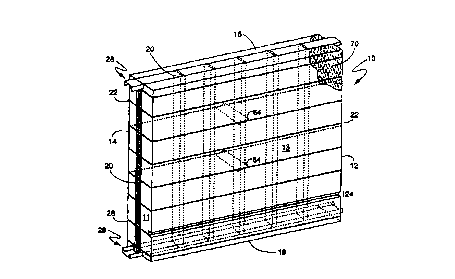
2o Fig. 1 shows a load-bearing bale 10 having substantially parallel opposed
end
surfaces 11 and 12, substantially parallel opposed side surfaces 13 and 14,
and
substantially parallel opposed upper and lower surfaces 16 and 18. The load-
bearing bale 10 is composed of a main portion of compressed fibrous material
70,
such as wheat straw, held together by cinctures 22 of baling twine, baling
wire, or
25 other banding material. Grooves 24 of the appropriate size and depth for
electrical
wiring , communication cabling, heating ducts, or central vacuum cleaner
piping are
cut or formed in the side faces of the bale at the desired heights (or cut in
a dovetail
shape to help hold the wiring, cabling, or vacuum piping in place before the
surtace
is plastered or stuccoed). Structural supports 20 extend along the end
surfaces 11
' 3o and 12, from the upper surface 16 to the lower surface 18. These
structural
supports 20 can be made of lumber (such as pine), of processed wood (such as
CA 02270547 1999-04-30
WO 98I19028 PCT/US97/19620
_g_
oriented strand board), or of various shapes of structural steel. The
structural
supports 20 are spaced throughout the load-bearing bale 10 to support roof and
snow loads and prevent lateral shifting.
The compressed straw 70 between the structural supports 20 is held in
compression by the cinctures 22 and in turn braces the thin dimension of the
structural supports 20. This creates a synergism allows the thickness of the
material used for structural supports 20 to be reduced, producing both
economic
and environmental savings compared with conventional construction.
The upper ends of the structural supports 20 snap into an inverted-lip U
o channel 28 that serves as bond beam on the upper surface 16) where the roof
is
attached. A second inverted-lip U channel 28 serves as a footing beam on the
lower surface 18 to secure the lower ends of the structural supports 20.
Fig. 2 is an exploded end view of the complete footing 34 to bond beam
assembly. It shows the inverted-lip U channel 28, which serves as the footing
~ 5 beam for the lower surface 18, fastened to the footing 34 by concrete
fasteners,
such as concrete nails or bolts 44. It also shows the inverted-lip U channel
28 that
serves as the bond beam at the upper surface 16, for tying the top of the
house
together and attaching the roof. The lips of the inverted-lip U channel 28
snap into
slots 30 to form an extremely strong connection. This connection is stronger
than
2o nailing and also makes assembly of the structure much faster than either
conventional framing or conventional straw bale construction.
Fig. 3 is an end view of the inverted-lip U channel 28, which shows inverted-
lip
U-channel sides 48 perpendicular to the inverted-lip U-channel web 46. The
inverted lips 50 at the upper edge of the inverted-lip U channel sides, are
bent back
25 ~ toward the inverted-lip U-channel web 46.
Fig. 4 is a detail view of one embodiment of the inverted-lip U channel 28
attachment to the structural supports 20. Multiple slots extending over a 2-
to 3-
inch length can be employed to ensure that the lips of the inverted-lip U
channel 28
are firmly attached to the structural support 20. The distance between the
inverted
30 lips 50 is less than the width of the structural support 20, so that when
inserted the
structural support 20 spreads the lips of the inverted-lip U channel 28,
creating a
CA 02270547 1999-04-30
WO 98/19028 PCT/US97/19620
_g_
continuous tension that forces the inverted lips 50 into the slots 30 to
maintain the
connection.
Fig. 5 shows the interface between two walls and a window opening 42. The
load-bearing bales 10 forming the corner are connected by means of banding 40,
- 5 which is driven through the load-bearing bales 10 behind the structural
supports 20
in several locations that are evenly spaced vertically. The ends of the
banding 40
are then tensioned and securely crimped. The same method of attachment is used
where the end surfaces 11 and 12 of the load-bearing bales 10 are butted
together,
such as above and below the window openings 42. The window opening 42 is
~o formed by cutting load-bearing bale segments of the appropriate that are
the width
of the desired window opening 42. The lower segment is the height of the
window
sill frame and the upper segment reaches from the window header to the bond
beam. Installation of windows and doors is quick and secure; the window or
door
frame attaches directly to the structural supports 20 located in the end
surfaces 11
~5 and 12 of each load-bearing bale, and to the inverted-lip U channels 28
that serve
as window header and window sill frame.
Lengths of U channel without invertedlips are screwed in place over abutting
sections of the inverted-lip U channels 28, that serve as the bond beam, to
create
U-channel splices 36. These complete the bond-beam tie along the straight
runs,
2o and U-channel corner splices 38 are screwed in place to complete the bond-
beam
tie around the house.
Fig. 6 is a perspective view of another embodiment of a load-bearing bale 10
which uses angle irons for structural supports 62 on both side surfaces 13 and
14.
One leg of each of these angle irons is embedded in the fibrous material as
the
25 bale is manufactured enabling the load-bearing bale 10 to be laid flat and
sandwiched between roof trusses 72 to provide both insulation and a base for
the
roof and ceiling as shown in Fig. 7.
Fig. 7 shows a perspective view of another embodiment of a load-bearing
bale 10 that uses angle-iron structural supports 62, similar to the embodiment
in
3o Fig. fi. However, at the lower surface 18 of the load-bearing bale 10, a
portion of
the leg of the angle-iron structural support 62 that is inserted into the bale
is cut
CA 02270547 1999-04-30
WO 98/19028 PCT/US97/19620
-10-
out. The portion of the other leg that extends below the bottom surface 18 is
bent
out at 90 degrees to form an attachment tab 66 for attaching the angle-iron
structural support 62 directly to the floor.
Fig. 8 is an exploded end view of a load-bearing bale 10 that uses an arrow-
s shaped cutout 55 in the structural support 20 to receive an anchor-shaped
structural connector 51 forming the attachment of the load-bearing bale 10 to
the
footing 34. The anchor-shaped structural connector 51 is made of two pieces of
sheet metal, each with a vertical web 52 and one leg 53 bent at about forty-
five
degrees and the other leg 54 bent at ninety degrees to the web 52. The
vertical
1o webs 52 of the two pieces are fastened together to form the anchor-shaped
structural connector 51. The side of the anchor-shaped structural connector 51
the
formed by the two ninety degree legs 54 attach to the footing 34 or to the
roof, and
the forty-five degree leg portions insert into the arrow-shaped cutout 55 at
both
ends of the structural support 20. This embodiment of the structural support
20 to
15 footing 34 connection would be very strong, but increase the difficulty of
removing a
load-bearing bale 10 that was misplaced during construction.
Fig. 9 is an exploded end view of another embodiment of the connection at the
upper surface 16 and lower surface 18 of a load-bearing bale 10) in which the
anchor-shaped structural connector 51 is inserted into serrated slots 56 in
both
2o ends of a structural support 20. This type of connection would facilitate
to removal
of a load-bearing bale 10 that was misplaced during construction: the forty-
five-
degree legs 53 of the anchor-shaped structural connector 51 can be squeezed
together slightly, allowing the load-bearing-bale 10 to be lifted off..
In Fig. 10, the inverted-lip U channel 28 is snapped over the heads of
25 staples 58 driven into the bottom end of the wooden structural support 20
at a forty
five degree angle. The upper end of the structural support 20 is equipped with
a
metal collar 60 that has serrations over which the lips of the inverted-lip U
channel 28 are snapped to make a strong, secure connection.
Fig. 11 shows another embodiment of a wooden structural support 20 with
3o multiple cinctures of wire 59 at both ends that create ridges over which
inverted-lip
U channel 28 can be snapped. This method and the metal collar 60, as shown in
CA 02270547 1999-04-30
WO 98I19028 PCT/US97/19620
_11_
Fig. 10, have an advantage over the staples 58 as shown at the bottom of Fig.
10 in
that there is no risk of splitting the wooden structural support.
Fig. 12 shows an inverted-lip U channel 28 with attachment tabs 68 that are
pre-punched and turned out to speed the attachment of trusses 72 to the
inverted-
lip U channel 28 that serves as the bond beam. The attachment tabs 68 that are
closest to the points at which the trusses 72 are to be attached are bent up,
the
truss 72 is shimmed square with the building, and then screws are driven
through
both the attachment tabs 68 and the shims, into the truss 72. The tabs fib
could
also be bent to the inside of the inverted-lip U channel to form the
connection as
shown in Fig. 18.
Fig. 13 is a perspective view of a building with the walls and parapet 80
constructed from load-bearing bales 10 having the same configuration as shown
in
Fig. 1, with an inverted-lip U channel 28 for the bond beam. The roof is made
from
load-bearing bales 10 having the same configuration as shown in Fig. 6, but
are
placed horizontally and sandwiched between flat roof trusses 72 that have an I-
shaped profile. The trusses 72 consist of a vertical web 78, an upper flange
7fi, and
a lower flange 74.
Fig 14 is a cross-sectional view of the roof portion of Fig. 13 showing the
angle-iron structural supports 62 on the side surfaces 13 and 14 of load-
bearing
2o bale 10, having the same configuration as Fig. 6. The structural supports
20 are
perpendicular to the trusses 72 and screwed to the upper and lower flanges 76
and 74 of the truss 72.
Fig. 15 shows a perspective view of a load-bearing bale 10 in a beam
configuration. The main portion of_compressed straw braces the structural
supports 20 on both side surfaces 13 and 14. There are grooves 24, for
electrical
conduits, on the upper side 16 and a nailer 84 of wood on the lower side 18.
The
use of compressed straw to provide bracing and prevent buckling makes it
cheaper
to fabricate esthetically appealing large beams with a minimum of wood or
steel.
The load-bearing bale in Fig. 16 has structural supports 20 on the corners
3o formed by the intersection of side surfaces 13 and 14 with upper surface
16, and
lower surface 18. The load-bearing bale has an expanded metal shell 82 that
runs
CA 02270547 1999-04-30
WO 98I19028 PCT/US97/19620
_12_
the entire length of the beam/post. This adds structural strength and
facilitates the
application of stucco or other finishes. The groove 24 on the lower surface 18
simplifies the routing of electrical cables.
Fig. 17 shows an end view of a toad-bearing bale which has structural support
provided by two U-shaped channels, made of expanded metal 82, that extend the
full length of the load-bearing bale. The bale is held in compression by
cinctures 22
that traverse the load-bearing bale lengthwise. The U- shaped channels are
held in
place and prevented from buckling away from the bale by cinctures 22 that are
evenly spaced along the length of the load-bearing bale 10, transverse to the
cinctures 22 that hold the bale in compression.
Fig. 18 is a perspective view of a load-bearing bale 10 connected to an
inverted-lip U channel by a metal bar that passes through holes in the
structural
supports 20 and holes in attachment tabs 68. This very strong connection
combined with the resilience of the compressed straw would allow the structure
to
flex in an earthquake.
Operation-Figs 1-18 -
Construction of a house using the load-bearing bales 10 involves the following
steps:
1. Determine the length of each of the various wall segments of the house. An
individual wall segment may be (a) from a corner to an opening) such as that
for a
window or door, or {b) any manageable length of load-bearing bale 10
(manageable
length depends on equipment available to handle the load-bearing bale 10 and
the
space constraints of the building site for turning and manipulating bales).
Each
. window opening 42 is also considered a wall segment.
2. Manufacture a load-bearing bale 10 of the proper length for each of the
wall
segments and window openings 42 of the house; install the upper inverted-lip U
channel 28, which will serve as the bond beam.
CA 02270547 1999-04-30
WO 98l19028 PCT/US97l19620
-13-
3. Cut out a portion of the appropriate load-bearing bales 10 for each window
opening 42. The bottom cut will be at the height of the window sill frame 41)
and the
upper cut will be at height of the window header 43. An inverted-lip U channel
28 is
installed on the lower side of the upper portion of the load-bearing bale,
above the
window opening 42, to serve as the window header 43. Another inverted-lip U
channel 28 is installed on the upper side of the lower portion of the cut toad-
bearing
bale 10, to serve as the window sill frame 41.
4. Fasten an inverted-lip U channel 28 to the footing 34 all the way around
the
structure, except at the doorways.
5. Beginning at one corner, erect the first wall segment by inserting the
lower
ends of the structural supports 20 into the inverted-lip U channel 28, that is
fastened to the footing 34. After bracing the wall segment, place a second
wall
segment to form the corner, and band the two segments together using bands 40
that are evenly spaced vertically. Then place the U-channel corner splice 38
over
the inverted-lip U channels 28 that form the bond beams of the two wall
segments
and screw it in place.
2o fi. Continue setting each load-bearing bale 10 wall segment in its proper
place,
including the pieces for above and below window openings 42; band each bale to
the previous one and screw the U-channel splices 36 and 38 in place at the
top.
How doors are treated will depend on wall height, but the U channel will
bridge the
door openings to complete the bond-beam tie.
7. If a flat roof is desired (as shown in Fig. 13), manufacture load-bearing
bales in
the configuration shown in Fig. 6, the width of the truss 72. Panels,
consisting of
one truss attached to either the upper surface 16 or lower surface 18 of a
load-
bearing bale, would be pre-assembled by screwing the ends of the structural
3o supports 62 to the upper flange 76 and lower flange 74 of the truss 72. The
panel
would be set in place and fastened to the inverted-lip U-channel 72 bond beam.
CA 02270547 1999-04-30
WO 98/19028 PCT/US97/19620
-14-
The next panel would be put in place, fastened to the inverted-lip U-channel
28
bond beam, and the unattached ends of the structural supports 20 opposite the
truss 72 of the current panel would be screwed to the previous truss 72. An
inverted-lip U-channel 28 footing beam for the parapet 80 would be screwed to
structural supports 62 and trusses T2 around the perimeter of the roof. Load-
bearing bates 10 having the same configuration as shown in Fig. 1 of the
desired
height for the parapet 80 would then be set into the parapet footing beam and
banded together.
8. The load-bearing bales in Figs. 15-17 would be manufactured, with or
without
internal structural supports 20, having the desired length, width, and height,
with
grooves 24 in the appropriate locations for electrical routing and
longitudinal
structural supports 20 if needed. The longitudinal structural supports 20,
that need
grooves 24, and nailers 84 would be placed in the grooves 24 and banded in
place
with cinctures 22. If an expanded metal 82 shell is used it would then be
applied
and banded in place with cinctures 22.
9. The connection shown in Fig. 18 would be slower to construct than the
embodiments shown in Fig. 2, and Figs. 8-11 that snap together. At the footing
34
2o the load-bearing-bale -10 wall segment would be held above the inverted-lip
U
channel 28 footing beam while a cable was threaded alternately through the
attachment tabs 68 of the inverted-lip U channel 28 and holes in the
structural
supports 10. The inverted-lips 50 would serve to align the holes in the
attachment
tabs 68 and structural supports 20 as the wall segment was lowered into place
and
the slack in the cable was taken up. Then one end of the cable would be
attached
to a metal rod 86 which would then be drawn through the holes to complete the
connection. The connection at the upper surface 16 would be accomplished in
the
same manner except the bale would not have to be suspended.
CA 02270547 1999-04-30
WO 98I19028 PCTlUS97l19b20
-15-
Ramifications and Scope
One can readily see that a load-bearing bale construction system is a very
rapid way to construct energy-efficient housing with Power embodied energy and
less on-site labor than conventional means of construction.
Although the description above contains many specificities, these should not
be construed as limiting the scope of the invention but as merely providing
illustrations of some of the presently preferred embodiments of this
invention. For
example, in another embodiment of the present invention, U channels without
1o inverted lips would receive the structural supports of load-bearing bales
(in the
configuration shown in Fig. 1 ), and cinctures would run vertically from under
the
footing beam and over the bond beam to tie the roof to the footing. The
grooves
can be shaped differently and placed differently, the structural supports can
be
made from different shapes and materials and placed differently in the bale)
and
~ 5 various methods can be used to connect the load-bearing bales together,
including
wire or rope. Even adhesive could be used as long as a structural supports are
present at the locations to be glued. The load-bearing bales and I-shaped
trusses,
of the configuration shown in Fig. 14, can be used in many orientations
including
the walls for mufti-story buildings.
Thus, the scope of the invention should be determined by the appended
claims and their legal equivalents, rather than by the examples given.