Language selection

Search

Patent 2270614 Summary

Third-party information liability

Some of the information on this Web page has been provided by external sources. The Government of Canada is not responsible for the accuracy, reliability or currency of the information supplied by external sources. Users wishing to rely upon this information should consult directly with the source of the information. Content provided by external sources is not subject to official languages, privacy and accessibility requirements.

Claims and Abstract availability

Any discrepancies in the text and image of the Claims and Abstract are due to differing posting times. Text of the Claims and Abstract are posted:

  • At the time the application is open to public inspection;
  • At the time of issue of the patent (grant).
(12) Patent Application: (11) CA 2270614
(54) English Title: FINGER PROTECTING ARRANGEMENT IN A SECTIONAL ROLL-TYPE DOOR
(54) French Title: DISPOSITIF DE PROTECTION DES DOIGTS POUR PORTE SECTIONNELLE
Status: Deemed Abandoned and Beyond the Period of Reinstatement - Pending Response to Notice of Disregarded Communication
Bibliographic Data
Abstracts

English Abstract


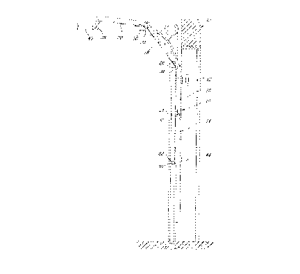
In a rolled-type door, such as a sectional garage door, wherein
a plurality of horizontal vertically adjacent are hingedly connected together
at their adjacent inside edges, a series of finger protecting joint members
are
disposed longitudinally between the adjacent panels. Each end face of an
adjacent panel is formed of a front and rear section defining a gap
therebetween in which is lodged a longitudinal sealing member. The end
faces of adjacent panels include complementary convex and concave sides
which, when the panels are angularly hinged relative to one another,
eliminates the presence of a gap usually present in conventional doors
thereby preventing accidental wedging of the fingers of the door operator.


Claims

Note: Claims are shown in the official language in which they were submitted.


CLAIMS
1. An overhead sectional door comprising a number of
panels successively hinged to one another by means of hinge connections
whose hinge axles are arranged close to the inner side of the door, each
panel being arranged between two adjacent panels having first and second
longitudinal end faces; a first joint member at said first longitudinal end
face,
said joint member having a pair of front and rear longitudinal sections
distanced from one another to define a gap therebetween; a first longitudinal
sealing member in said gap; said rear section defining a U-shape with inner
and outer planar sides and an intermediate side connecting said inner and
outer sides; said front section defining a planar outer side, a concave inner
side and a rounded intermediate side connecting said planar outer side and
said concave inner side; said intermediate side of said front section
extending below said hinge axle when said door is in a planar position; a
second joint member at said second longitudinal end face; said second joint
member having a pair of front and rear longitudinal sections distanced from
one another to define a gap therebetween; a second longitudinal sealing
member in said gap; said rear section of said second front joint member
defining a U-shape with inner and outer planar sides and an intermediate
side connecting said inner and outer sides; said front section of said second
front member defining a V-shape with a planar inner side and a convex front
side and an inwardly rounded portion whereby, when said door is in said
planar position, said planar inner side and said convex outer side of said
second joint member are received within a recess formed by said inner side
of said rear section of said first joint member and said concave inner side of
said front section of said first joint member; contact between said first and

second joint members being mainly effected on said first and second sealing
members.
2. An overhead sectional door as defined in claim 1,
wherein said rounded intermediate side of said front section of said first
joint
member is partially received in said inwardly rounded portion of said front
section of said second joint member.
3. An overhead sectional door as defined in claim 1 or 2,
wherein both said sealing members are made of a flexible plastic material.
4. An overhead sectional door as defined in claim 1, 2 or
3, wherein both said sealing members have a Y-shaped section.

Description

Note: Descriptions are shown in the official language in which they were submitted.


CA 02270614 1999-OS-03
-1-
TITLE OF THE INVENTION
Finger protecting arrangement in a sectional roll-type door.
FIELD OF THE INVENTION
The present invention pertains to a protective configuration in
the longitudinal end faces of panels of a roll type door, such as a sectional
garage door, wherein a plurality of horizontal vertically adjacent panels are
hingedly connected together at their adjacent inside edges and are adapted
to cooperate with tracks to slide from a vertical close position to a
horizontal
overhead open position, and vice-versa.
BACKGROUND OF THE INVENTION
When door constructions of the type described above are
moved from a horizontal open position to a vertical close position, a V-shape
gap is created between adjacent front edges of each pair of cooperating
panels during the period when the panels move around the curved portions
of the tracks. Hence, some danger exists to the door operator fingers during
the time the gaps are closed when the door approaches a vertical planar
position during the door closing operation.
Protection to the operator is therefore important and some
protecting devices have been devised, one of which for example is described
in applicant's co-pending Canadian patent application serial number
2,256,662 in the name of Pierre Juneau wherein a protective strip is provided
between the facing adjacent edges of the panels and partially covers both
inner and outer faces of the panel.

CA 02270614 1999-OS-03
-2-
OBJECTS AND STATEMENT OF THE INVENTION
An object of the present invention is to provide an improved
safety configuration on the longitudinal end faces of adjacent panels of the
type of door described.
This is achieved by providing a configuration which will prevent
an operator's fingers to be inserted in the gap formed by two angularly
disposed panels during the closing or opening of the door.
The present invention therefore relates to an overhead
sectional door which comprises a number of panels successively hinged to
one another by means of hinge connections whose hinge axles are arranged
close to the inner side of the door, each panel being arranged between two
adjacent panels having first and second longitudinal end faces; a first joint
member at the first longitudinal end face, the joint member having a pair of
front and rear longitudinal sections distanced from one another to define a
gap therebetween; a first longitudinal sealing member in the gap; the rear
section defining a U-shape with inner and outer planar sides and an
intermediate side connecting the inner and outer sides; the front section
defining a planar outer side, a concave inner side and a rounded
intermediate side connecting the planar outer side and the concave inner
side; the intermediate side of the front section extending below the hinge
axle when the door is in a planar position; a second joint member at the
second longitudinal end face; the second joint member having a pair of front
and rear longitudinal sections distanced from one another to define a gap
therebetween; a second longitudinal sealing member in the gap; the rear
section of the second joint member defining a U-shape with inner and outer
planar sides and an intermediate side connecting the inner and outer sides;
the front section of the second joint member defining a V-shape with a planar
inner side and a convex front side and an inwardly rounded portion whereby,
when the door is in the planar position, the planar inner side and the convex

CA 02270614 1999-OS-03
-3-
outer side of the second joint section are received within a recess formed by
the inner side of the rear section of the first joint member and the concave
inner side of the front section of the first joint member; contact between the
first and second joint members being mainly effected on the first and second
sealing members.
In one form of the invention, both sealing members are made
of a flexible plastic material.
Other objects and further scope of applicability of the present
invention will become apparent from the detailed description given
hereinafter. It should be understood, however, that this detailed description,
while indicating preferred embodiments of the invention, is given by way of
illustration only, since various changes and modifications within the spirit
and
scope of the invention will become apparent to those skilled in the art.
IN THE DRAWINGS
Figure 1 is a cross-sectional view of a garage door showing
some panels extending between a vertical close position and a horizontal
open position;
Figure 2 is a cross-sectional view of a panel used in the door
illustrated in figure 1;
Figure 3 is an enlarged sectional view showing the longitudinal
end face configuration of two adjacent panels;
Figure 4 is a view similar to that illustrated in figure 3, but
illustrating the hinge axle; and
Figure 5 is a schematic view showing adjacent panel ends in
an angularly hinged position relative to one another.

CA 02270614 1999-OS-03
-4-
DESCRIPTION OF PREFERRED EMBODIMENTS
Referring to figure 1, a door 10 closing a garage front wall 12
comprises a plurality of horizontal vertically disposed panels 14, 16, 18 and
20. These panels are hingedly connected by means of hinges 22, 24, 26
and 28 which are attached respectively adjacent the upper and lower edges
of each pair of adjacent panels. These hinges are preferably connected to
the panels in usual manner, that is to their inside surfaces by means of
screws or the like so that the panels respectively are free to hinge inwardly
in the manner shown in figure 1, that is to permit them to move to an
overhead horizontal position when the door is opened. Mounted at each
vertical side edge of each of the panel, rollers 30, 32, 34 and 36 and 38 are
provided in cooperating engagement with tracks, one of which is shown as
40, so that the door as a whole is free to follow the tracks to be moved up
and down for opening and closing the door opening. Handles 42 and 44 are
provided to an operator on the front side of the door for opening and closing
the door.
The present invention is concerned with providing an improved
configuration of the longitudinal end faces of the adjacent panels. Referring
to figure 2, one example of such panel is shown as 18 and comprises a front
side 50 and a rear side 52 with opposite longitudinal joint members 54 and
56.
Referring also to figures 3, 4 and 5, the joint member 54 is
formed of a pair of front and rear longitudinal sections 58 and 60 which are
distanced from one another to define a gap in which is lodged a Y-shaped
sealing member 62. The rear section defines a U-shape with inner and outer
planar sides 64 and 66 and an intermediate side 68 connecting the inner and
outer sides. The front section 58 defines a planar outer side 70, a concave
inner side 72 and a rounded intermediate side 74 which extends below the
hinge axle 76 by a distance "x" when the door is in a planar position, either

CA 02270614 1999-OS-03
-5-
closed or opened. The second joint member 56 has a pair of front and rear
sections 80 and 82 which are distanced from one another so as to define in
a gap in which is lodged a sealing member 84. The rear section 80 defines
a U-shape with inner and outer planar sides 86 and 88 and an intermediate
side 90 connecting the inner and outer sides. The front section defines an
inverted V-shape with a planar inner side 92 and a convex front side 94
which displays in its lower part an inwardly rounded portion 96. As can be
seen, in figure 3, in the planar vertical or horizontal position, the rounded
side
74 is lodged in the inwardly rounded portion 96. However, in the vertical
position, the load is supported mainly by the two sealing members 62 and 84
which are formed of a flexible plastic material such as PVC.
As can be seen in figure 5, in the most extreme angularly
hinged position of two adjacent panels, there is no gap existing in which an
operator's fingers could be inserted.
Although the invention has been described above with respect
with one specific form, it will be evident to a person skilled in the art that
it
may be modified and refined in various ways. It is therefore wished to have
it understood that the present invention should not be limited in scope,
except by the terms of the following claims.

Representative Drawing
A single figure which represents the drawing illustrating the invention.
Administrative Status

2024-08-01:As part of the Next Generation Patents (NGP) transition, the Canadian Patents Database (CPD) now contains a more detailed Event History, which replicates the Event Log of our new back-office solution.

Please note that "Inactive:" events refers to events no longer in use in our new back-office solution.

For a clearer understanding of the status of the application/patent presented on this page, the site Disclaimer , as well as the definitions for Patent , Event History , Maintenance Fee  and Payment History  should be consulted.

Event History

Description Date
Application Not Reinstated by Deadline 2005-05-03
Inactive: Dead - RFE never made 2005-05-03
Deemed Abandoned - Failure to Respond to Maintenance Fee Notice 2005-05-03
Inactive: Abandon-RFE+Late fee unpaid-Correspondence sent 2004-05-03
Application Published (Open to Public Inspection) 2000-11-03
Inactive: Cover page published 2000-11-02
Inactive: IPC assigned 1999-06-22
Inactive: First IPC assigned 1999-06-22
Inactive: Filing certificate - No RFE (English) 1999-06-03
Application Received - Regular National 1999-06-02

Abandonment History

Abandonment Date Reason Reinstatement Date
2005-05-03

Maintenance Fee

The last payment was received on 2004-03-18

Note : If the full payment has not been received on or before the date indicated, a further fee may be required which may be one of the following

  • the reinstatement fee;
  • the late payment fee; or
  • additional fee to reverse deemed expiry.

Patent fees are adjusted on the 1st of January every year. The amounts above are the current amounts if received by December 31 of the current year.
Please refer to the CIPO Patent Fees web page to see all current fee amounts.

Fee History

Fee Type Anniversary Year Due Date Paid Date
Application fee - standard 1999-05-03
MF (application, 2nd anniv.) - standard 02 2001-05-03 2001-04-20
MF (application, 3rd anniv.) - standard 03 2002-05-03 2002-04-22
MF (application, 4th anniv.) - standard 04 2003-05-05 2003-04-28
MF (application, 5th anniv.) - standard 05 2004-05-03 2004-03-18
Owners on Record

Note: Records showing the ownership history in alphabetical order.

Current Owners on Record
PIERRE JUNEAU
Past Owners on Record
None
Past Owners that do not appear in the "Owners on Record" listing will appear in other documentation within the application.
Documents

To view selected files, please enter reCAPTCHA code :


To view images, click a link in the Document Description column (Temporarily unavailable). To download the documents, select one or more checkboxes in the first column and then click the "Download Selected in PDF format (Zip Archive)" or the "Download Selected as Single PDF" button.

List of published and non-published patent-specific documents on the CPD .

If you have any difficulty accessing content, you can call the Client Service Centre at 1-866-997-1936 or send them an e-mail at CIPO Client Service Centre.


Document
Description 
Date
(yyyy-mm-dd) 
Number of pages   Size of Image (KB) 
Representative drawing 2000-10-19 1 10
Cover Page 2000-10-19 1 37
Description 1999-05-02 5 202
Claims 1999-05-02 2 62
Abstract 1999-05-02 1 20
Drawings 1999-05-02 4 88
Filing Certificate (English) 1999-06-02 1 165
Reminder of maintenance fee due 2001-01-03 1 112
Reminder - Request for Examination 2004-01-05 1 123
Courtesy - Abandonment Letter (Request for Examination) 2004-07-11 1 166
Courtesy - Abandonment Letter (Maintenance Fee) 2005-06-27 1 175
Fees 2003-04-27 1 34
Fees 2002-04-21 1 39
Fees 2001-04-19 1 39
Fees 2004-03-17 1 38