Note: Descriptions are shown in the official language in which they were submitted.
CA 02270924 1999-OS-06
WO 98I30382 PCT/I1S98/00114
TRANSVERSELY AND AXIALLY REINFORCED PULTRUSION PRODUCT
BACKGROUND OF THE INVENTION
The present invention relates to reinforced pultrusion products and, in
particular, to a pultrusion product reinforced with glass fibers, wherein a
portion of the
glass fibers are buckled so as to provide transverse reinforcement, and a
process for
production of such a reinforced pultrusion product.
According to conventional pultrusion methodology, where it is required to
axially and transversely reinforce thermoplastic or thermoset structures to
provide
transverse and axial strength, a woven, stitched, or non-woven fabric or mat
of glass fibers
is added to the thermoplastic or thermoset material. However, with
thermoplastic
pultrusion, it is preferable that the mat or fabric be pre-impregnated with
the thermoplastic
material or layered with thermoplastic fibers to get good wetout of the glass.
Such pre-
impregnation or layering steps represent an expensive and time consuming
addition to
conventional thermoplastic pultrusion processes.
Accordingly, there is a need for an inexpensive axially and transversely
reinforced pultrusion product and a corresponding inexpensive and convenient
pultrusion
process for producing such a product.
SUMMARY OF THE INVENTION
This need is met by the present invention wherein a reinforced pultrusion
product is provided including buckled, longitudinally oriented, reinforcement
fibers. The
pultrusion product is formed in a pultrusion apparatus by heating a set of
composite
strands while allowing polymeric fibers in some of the strands to shrink, thus
causing
associated reinforcement fibers within those composite strands to buckle.
In accordance with one embodiment of the present invention, a reinforced
pultrusion product is provided comprising a polymeric matrix having a first
end portion
and a second end portion, and defining a pultrusion product axis extending
from the first
end portion to the second end portion, and at least one buckled reinforcement
fiber
embedded in the polymeric matrix and extending in a direction substantially
parallel to
the pultrusion product axis. The reinforced pultrusion product preferably
further
-1_
CA 02270924 1999-OS-06
WO 98/30382 PCT/US98100114
comprises at least one linear reinforcement fiber embedded in the polymeric
matrix and
extending in a direction substantially parallel to the pultrusion product
axis.
The polymeric matrix may comprise a fiberizable thermoplastic material,
e.g., a material selected from the group consisting of polyethylene
terephthalate,
polybutylene terephthalate, nylon, polypropylene, and polyphenylene sulfide.
The
buckled reinforcement fiber may comprise a material selected ftom the group
consisting
of glass, graphite, an aramid material, a metal such as steel, and a metal
coated material.
The linear reinforcement fibers may outnumber the buckled reinforcement
fibers.
Specifically, a ratio of linear to buckled reinforcement fibers may be
approximately 85 to
15; however, the ratio may also be 15 to 85 or some other ratio depending upon
the
loading requirements of the intended application and design of the pultrusion
product.
The polymeric matrix may comprise about 20% to about 80% of the weight of the
reinforced pultrusion product. The pultrusion product may comprise a sheet of
material
having a thickness of about 0.0l " (0.254 mm) to about 1 " (2.54 cm),
preferably, about
0.05" ( 1.27 mm), and a width of up to approximately 6" (76.2 mm). It is
contemplated by
the present invention that the width of the pultrusion product is a function
of the design of
the pultrusion die utilized to form the reinforced product.
In accordance with another embodiment of the present invention, a
reinforced pultrusion product comprises a polymeric matrix having a first end
portion and
a second end portion, and defining a pultrusion product axis extending from
the first end
portion to the second end portion, and at least one substantially non-linear
reinforcement
fiber embedded in the polymeric matrix. The non-linear reinforcement fiber
extends from
a first non-linear reinforcement fiber end to a second non-linear
reinforcement fiber end
along a non-linear path, wherein the non-linear path extends in a longitudinal
direction,
and wherein the longitudinal direction is substantially parallel to the
pultrusion product
axis. The reinforced pultrusion product preferably further comprises at least
one axial
reinforcement fiber embedded in the polymeric matrix. The axial reinforcement
fiber
extends from a f rst axial reinforcement fiber end to a second axial
reinforcement fiber
end along a linear path, wherein the linear path is substantially parallel to
the pultrusion
product axis.
-2-
CA 02270924 1999-OS-06
WO 98130382 PCT/US98/00114
In accordance with yet another embodiment of the present invention, a
pultrusion process is provided wherein a set of composite strands are
tensioned as they are
consolidated in a pultrusion die, the process comprises the steps of:
providing a set of
composite strands wherein each of the strands comprises at least one
reinforcement fiber
and at least one polymeric fiber; designating one or more of the composite
strands as a
first subset of the set of composite strands and designating one or more of
the composite
strands as a second subset of the set of composite strands; applying a
supplemental
tension force to each of the one or more strands of the first subset of
strands; heating the
set of composite strands such that the at least one polymeric fiber of each of
the one or
more strands within the second subset of composite strands shrinks to cause
the
reinforcement fiber in each of the one or more strands of the second subset of
composite
strands to buckle; and consolidating the heated set of composite strands in a
pultrusion die
assembly to form a reinforced pultrusion product.
The polymeric fiber may comprise a polymeric fiber prestretched or
partially or fully oriented. The supplemental tension force may range from
about 2 Ibf
(8.88 N) to about 25 lbf (111 N) per strand. The supplemental tension force is
preferably
applied to each of the one or more strands of the first subset of strands by a
tensioning
assembly as the one or more strands of the first subset of strands pass
through the
tensioning assembly without applying a supplemental tension force to the one
or more
strands of the second subset of strands.
The heating step may comprise heating the composite strands to a
preforming temperature, wherein the preforming temperature is less than the
melting point
temperature of the at least one polymeric fiber. The preforming temperature
may be about
°F { 15 °C) less than the melting point temperature of the at
least one polymeric fiber.
25 The consolidation step may comprise applying ultrasonic vibration to a
portion of the
pultrusion die.
In accordance with yet another embodiment of the present invention, a
pultrusion apparatus is provided comprising: a composite strand supply
assembly
operative to provide first and second subsets of one or more composite
strands. Each of
the composite strands includes at least one reinforcement fiber and at least
one polymeric
fiber. The apparatus further includes a composite strand tensioning assembly
arranged
-3-
CA 02270924 1999-OS-06
WO 98I30382 PCT/US98/00114
such that the one or more strands of the first subset of composite strands are
tensioned by
the tensioning assembly; a preforming assembly operative to heat the first and
second
subsets of composite strands such that the at least one polymeric fiber of
each of the one
or more strands of the second subset of composite strands shrinks to cause the
at least one
reinforcement fiber in each of the one or more strands of the second subset of
composite
strands to buckle; and a pultrusion die assembly operative to form a
pultrusion product
with the heated composite strands.
The composite strand supply assembly preferably comprises a plurality of
discrete composite strand sources. The composite strand tensioning assembly
preferably
comprises a set of one or more tensioning bars or other tensioning devices in
contact with
the first subset of one or more composite strands. The preforming assembly may
include
a perforated plate adapted to arrange the first and second subsets of
composite strands
relative to one another. The pultrusion die assembly may comprise an
ultrasonic
pultrusion die assembly.
Accordingly, it is an object of the present invention to provide a low cost
reinforced pultrusion product wherein a portion of its reinforcement fibers
are buckled so
as to provide transverse reinforcement, and a corresponding low cost process
and
apparatus for production of such a reinforced pultrusion product.
BRIEF DESCRIPTION OF THE DRAWINGS
Fig. 1 is a schematic illustration, partially broken away, of a pultrusion
process and apparatus according to the present invention;
Fig. 2 is a schematic illustration of a reinforced pultrusion product
according to the present invention;
Fig. 2A is a schematic illustration of a portion of the reinforced pultrusion
product shown in Fig. 2; and
Fig. 3 is a perspective view of a reinforced pultrusion product according to
the present invention wherein the product includes a U-shaped cross section.
DETAILED DESCRIPTION AND
PREFERRED EMBODIMENTS OF THE INVENTION
Referring to Fig. 1, a pultrusion apparatus 10 according to one embodiment
of the present invention comprises a composite strand supply assembly I 2, a
composite
-4-
CA 02270924 1999-OS-06
WO 98/30382 PCT/US98/00114
strand tensioning assembly 14, a preforming assembly 16, and a pultrusion die
assembly
18.
The composite strand supply assembly 12 comprises a plurality of discrete
composite strand sources in the form of a series of spools 20 mounted on a
creel 22. Each
spool 20 includes a composite strand 24 wound about the spool 20. Each
composite
strand 24 is fed through a corresponding guide eye 23. In this manner, the
composite
strand supply assembly 12 is operative to provide a first subset of composite
strands 26
and a second subset of composite strands 28.
The composite strand tensioning assembly 14, which includes a set of
tensioning bars or other tensioning devices 15, e.g. weights, spring loaded
devices, in
contact with the first subset of composite strands 26, is arranged such that
the first subset
of composite strands 26 are tensioned by the tensioning assembly 14. In a
particular
embodiment of the present invention, a total of 54 composite strands are
supplied by the
supply assembly 12. The first subset of composite strands 26 includes forty
six (46) of
1 S the fifty four (54) composite strands 24 while the second subset of
composite strands 28
includes the remaining eight (8) composite strands 24.
Each composite strand 24 includes reinforcement and polymeric fibers
which are not shown in Fig. 1 because they would not be discernable in a
figure of the
illustrated scale. U.S. Patent Application Serial No. 08/311,817, filed
September 26,
1994, the disclosure of which is incorporated herein by reference, teaches a
manner of
producing the composite strand 24. The reinforcement fibers comprise a
material selected
from the group consisting of glass, including S-glass and E-glass, a hollow
fiber, graphite,
an aramid material, metal or metal coated fibers, and any other fiberizable
reinforcement
material. The polymeric fibers comprise a material selected from the group
consisting of
polyethylene terephthalate, polybutylene terephthalate, nylon, polypropylene,
polyphenylene sulfide and any other fiberizable thermoplastic material.
Additionally, the
polymeric fibers utilized in the present invention are those which tend to
shrink under the
heat of the preforming assembly 16. For example, polymeric fibers which are
stretched or
oriented during their production to yield higher tensile strength are subject
to shrinkage
upon heating and, accordingly, are suitable for use with the present
invention.
-5-
CA 02270924 1999-OS-06
WO 98130382 PCTlUS98100114
In one embodiment of the present invention, the reinforcement fibers
comprise E-glass fibers having a cross sectional diameter of about 15 microns
to about 23
microns and the polymeric fibers comprise polypropylene fibers having like
size to
achieve good wetout. The composite strands may comprise about 15% to about 85%
by
weight reinforcement fibers but for better wetout and less waste, about 40% to
about 60%
polymer has achieved good product properties.
The preforming assembly 16 includes a perforated plate 17 having
apertures through which respective composite strands 24 are threaded in order
to position
the composite strands 24 relative to one another in an arrangement
approximating the
final desired shape of a pultrusion product 30. The preforming assembly 16 is
operative
to heat the first and second subsets of composite strands 26, 28. Upon
exposure to the
heat generated by the preforming assembly 16 the polymeric fibers of the first
and second
subsets of composite strands 26, 28 shrink.
The shrinkage of the polymeric fibers in a particular composite strand 24
within the second subset of composite strands 28 creates a gathering force
which causes
corresponding reinforcement fibers in the same composite strand 24 to buckle,
i.e.,
assume substantially non-linear orientations. The reinforcement fibers are
forced to
buckle in response to the gathering forces because the reinforcement fibers do
not shrink
with the polymeric fibers. The shrinkage of the polymeric fibers in a
particular composite
strand 24 within the first subset of composite strands 26 does not cause
corresponding
reinforcement fibers in the same composite strand to buckle because of the
supplemental
tension applied to the first subset of composite strands 26.
The pre-heated composite strands 24 are consolidated in the pultrusion die
assembly 18 to form a pultrusion product 30 having a desired cross section
defined by the
particular shape of the pultrusion die assembly 18. A pulling roller assembly
32 pulls the
pultrusion product 30 in an axial direction during pultrusion. This pulling
tends to reduce
the buckling created in the reinforcement fibers. Accordingly, the pultrusion
die assembly
18 can be selected such that the buckling is not substantially reduced during
pultrusion.
The ultrasonic pultrusion die assembly disclosed in U.S. Patent No. 5,091,036,
to Taylor,
wherein ultrasonic vibration is applied to a portion of a pultrusion die, is
an example of a
pultrusion apparatus which minimizes pulling tension through the die assembly
and, as a
-6-
CA 02270924 1999-OS-06
WO 98I30382 PCT/US98/00114
result, is well suited for use with the present invention. It is contemplated
by the present
invention, however, that pultrusion dies other than ultrasonic pultrusion die
assemblies
may be used. A product cooling section 34, preferably a cooling water mist
sprayer, is
provided down line of the pultrusion die assembly 18 to cool the pultrusion
product 30 at
a rate faster than would be possible through mere exposure to ambient air.
In operation, with further reference to Fig. 1, although a11 of the composite
strands 24 are tensioned to a degree as they are pulled through the pultrusion
die assembly
18 by the pulling roller assembly 32, the tensioning devices 15 of the
composite strand
tensioning assembly 14 apply a supplemental tension force to the first subset
of composite
strands 26 as the first subset of strands 26 are pulled through the tensioning
assembly 14.
The supplemental tension force prevents buckling of the reinforcing fibers in
the first
subset of strands 26 as they pass through the preforming assembly 16 and the
pultrusion
die assembly 18. The magnitude of the supplemental tension force is at least
large
enough to ensure that the reinforcing fibers in the first subset of strands 26
do not buckle.
For example, where the polymeric fibers comprise polypropylene and where
reinforcement fibers comprise E-glass fibers, the supplemental tension applied
to the first
subset of strands 26 is approximately 10 lbf (44.4 N) while the tension in the
second
subset of strands 28 is merely that which is necessary to unload the strands
from the
composite strand supply assembly 12 and pull the strands through the
preforming
assembly 16 and the pultrusion die assembly 18.
As is noted above, because no supplemental tension is applied to the
second subset of composite strands 28 in the illustrated embodiment and
because the
pultrusion die assembly 18 and the pulling roller assembly 32 are arranged
such that the
necessary pulling tension is not great enough to prevent at least some amount
of buckling
of the reinforcing fibers, the shrinkage of the polymeric fibers within the
second subset of
composite strands 28 causes the reinforcement fibers within the second subset
of
composite strands 28 to buckle, i.e., bend or warp. It is contemplated by the
present
invention that different levels of buckling may be achieved by varying the
degree to
which the polymeric fibers are prestretched or oriented. Specifically, a
polymeric fiber
which is stretched to six times its normal length during orientation of the
fiber will cause
CA 02270924 1999-OS-06
WO 98130382 PCT/US98/00114
proportionally more buckling than a polymeric fiber which is stretched to
twice its normal
length during orientation.
In the preforming assembly 16, the composite strands 24 are heated to a
preforming temperature on the order of about 350°F (l75°C) to
about 400°F (200°C}. For
example, in one embodiment of the present invention, the preforming
temperature is about
25°F (15°C) less than the melting point temperature of the
polymeric fibers.
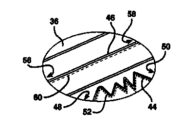
Referring now to Figs. 2 and 2A, where like elements are referenced by
like reference numerals, a cut or discrete reinforced pultrusion product 30'
formed from
the pultrusion product 30 shown in Fig. 1 comprises a polymeric matrix 36
having a first
end portion 38 and a second end portion 40 and defines a pultrusion product
axis 42
extending from the first end portion 38 to the second end portion 40. The
polymeric
matrix is formed, through the pultrusion process described above, from the
polymeric
fibers present in the composite strand 24. At least one buckled reinforcement
fiber 44 is
embedded in, i.e., at least partially surrounded by, the polymeric matrix 36
and extends in
a direction substantially parallel to the pultrusion product axis 42. The
reinforced
pultrusion product 30' further comprises at least one linear reinforcement
fiber 46
embedded in the polymeric matrix 36 and extending in a direction substantially
parallel to
the pultrusion product axis 42. In the illustrated embodiment, the buckled and
linear
reinforcement fibers 44, 46 are formed, through the pultrusion process
described above,
from the reinforcement fibers present in the composite strands 24. The
pultrusion product
30' is axially reinforced by the linear reinforcement fibers 46 and is
transversely
reinforced by the buckled reinforcement fibers 44.
The buckled reinforcement fibers 44 comprise substantially non-linear
reinforcement fibers, each extending from a first non-linear reinforcement
fiber end,
indicated generally at 48, to a second non-linear reinforcement fiber end,
indicated
generally at 50, along a non-linear path, indicated generally by the dashed
line 52. In the
illustrated embodiment, the first and second non-linear reinforced fiber ends
extend to the
first and second end portions 38, 40 of the matrix 36. However, it is
contemplated that the
first and second non-linear reinforcement fibers may have a length which is
less than the
longitudinal length of the matrix 36 and, hence, would not extend to both end
portions 38,
of the matrix 36. The non-linear path 52 generally extends in a longitudinal
direction,
_g_
CA 02270924 1999-OS-06
WO 98/30382 PCT/US98/00114
indicated generally by arrows 54. The longitudinal direction 54 is
substantially parallel to
the pultrusion product axis 42. The linear reinforcement fibers 46 comprise
axial
reinforcement fibers, each extending from a first axial reinforcement fiber
end, indicated
generally at 56, to a second axial reinforcement fiber end, indicated
generally at 58, along
a linear path, indicated generally by dashed lines 60. The first and second
axial
reinforcement fiber ends 56, 5 8 extend to the first and second end portions 3
8, 40 of the
matrix 36 in the illustrated embodiment. The linear path 60 is also
substantially parallel
to the pultrusion product axis 42.
The relative number of buckled and linear reinforcement fibers 44, 46
present in the reinforced pultrusion product may vary depending upon the
desired degrees
of transverse and axial reinforcement for a particular pultrusion product. In
one
embodiment of the present invention, the plurality of linear reinforcement
fibers
outnumber the buckled reinforcement fibers. Specifically, the ratio of linear
to buckled
reinforcement fibers is approximately 85 to 15. Similarly, the relative
amounts of and
placement of polymeric material and reinforcement fibers in the reinforced
pultrusion
product varies depending upon the desired properties of a particular
pultrusion product.
In one embodiment of the present invention, the polymeric matrix can vary but
best
results are achieved with about 40% to about 50% of the total weight of the
reinforced
pultrusion product comprising polymeric material. The dimensions of the
pultrusion
product itself also vary from application to application.
It is contemplated by the present invention that more than one type of
reinforcement fiber may be utilized within the pultrusion product 30' such
that the
reinforcement fibers include at least a first set of reinforcement fibers
comprising a first
reinforcement fiber material and at least a second set of reinforcement fibers
comprising a
second reinforcement fiber material. For example, since aramid fibers tend to
be stronger
but more expensive than many reinforcement fibers, to achieve increased
strength at a
lower cost, the pultrusion process described above may be adapted such that
10% of the
reinforcement fibers are aramid fibers while the remaining reinforcement
fibers are made
from another appropriate material. Similarly, 10% of the reinforcement fibers
could be a
conductive material while the remaining reinforcement fibers are formed from
another
appropriate material.
-9-
CA 02270924 1999-OS-06
WO 98/30382 PCT/ITS98/00114
It is further contemplated by the present invention that one or more non-
composite reinforcing fiber strands may be combined with the composite strands
during
the pultrusion process such that the non-composite strands are embedded within
the
matrix of the final pultrusion product. The non-composite reinforcing fiber
strands may
be provided in the form of spools mounted on the creel 22. The reinforcing
fiber strands
may be formed from a material selected from the group consisting of glass,
including S-
glass and E-glass, hollow fibers, graphite, an aramid material, metal, or a
metal coated
materi al.
Referring now to Fig. 3, it is contemplated by the present invention that the
I O reinforced pultrusion product 30' may be of an elongated channel design
incorporating a
U-shaped cross section. In this manner, the reinforced pultrusion product 30'
functions as
a structural member resistant to torsional stresses. For example, although the
number of
tensioned and non-tensioned strands will vary according to the needs of the
particular
product, in one embodiment of the present invention incorporating the U-shaped
cross
section, 50% of the strands are tensioned and SO% of the strands are not
tensioned.
Having described the invention in detail and by reference to preferred
embodiments thereof, it will be apparent that modifications and variations are
possible
without departing from the scope of the invention defined in the appended
claims. It is
further contemplated that supplemental tension forces may be applied to the
second subset
of composite strands 28. However, the supplemental tensioning of the first
subset of
composite strands 26 should exceed that of the second subset of strands 28.
-10-