Note: Descriptions are shown in the official language in which they were submitted.
CA 02271395 1999-OS-07
SJ-10489CA
- 1 -
TITLE: MOLDING APPARATUS WITH MOLD BLOCK REPLACEMENT
SYSTEM
FIELD OF THE INVENTION
The present invention relates to a system for
replacing mold blocks in a moving mold tunnel molding
apparatus. According to the present invention, the mold
blocks are replaced without interrupting operation of the
molding apparatus.
BACKGROUND OF THE INVENTION
Molding apparatus, such as pipe molds, have mold
blocks which continuously move around an endless track. On
one side of the track the mold blocks are in a closed
condition to form a moving mold tunnel where product is
shaped within the molding apparatus. The mold blocks open
at the downstream end of the tunnel to release the product
and are then recirculated back to the upstream end of the
mold tunnel.
There are currently two different styles of molding
apparatus having moving mold tunnels. According to one of
these styles which is known as a clam shell type molder, a
pair of mold block sections are mounted on a common carrier
which circulates around a single looped track. The mold
block sections hinge to open and close relative to one
another on opposite sides of the track.
The other style of moving mold tunnel apparatus is
formed by a pair of endless tracks and the mold blocks are
formed by mold block sections mounted on carriers of the
two tracks. The two tracks have track portions which
extend side by side parallel with one another where the
mold block sections from the two tracks meet to form the
CA 02271395 1999-OS-07
SJ-10489CA
- 2 -
moving mold tunnel.
In the past, it has been necessary for mold block
replacement to stop movement of the mold blocks in a moving
mold tunnel type apparatus. According to prior art
replacement methods the mold blocks must be stationary in
order to release them from the track and replace them with
new mold blocks.
This known method of mold block replacement results
in a number of drawbacks. Firstly, it is time inefficient
in that the molding operation must be shut down during the
replacement. Secondly, it can result in hazardous
conditions as a result of the shut down. Specifically,
when the shut down occurs, there is a possibility of
dangerous plastic build up in the extrusion equipment which
must be cleared before the extrusion equipment can be
started up again.
SUMMARY OF THE PRESENT INVENTION
The present invention provides molding apparatus
having a moving mold region in which mold block replacement
is carried out without having to interrupt operation of the
molding apparatus.
In particular, the molding apparatus of the present
invention, which is used in a continuous molding operation,
comprises looped endless track means, track carriers which
are moved around said track means to and from a product
shaping mold region, and a transfer system for replacement
of mold block members used in the apparatus without
interrupting the molding operation. The transfer system
comprises transfer carriers controlled to move synchronized
with the track carriers at a transfer location remote from
CA 02271395 1999-OS-07
SJ-10489CA
- 3 -
the mold region and means to slide the mold block members
between the track carriers and the transfer carriers at the
transfer location.
BRIEF DESCRIPTION OF THE DRAWINGS
The above as well as other advantages and features
of the present invention will be described in greater
detail according to the preferred embodiments of the
present invention in which;
Figure 1 is a side view of a molding apparatus
according to a preferred embodiment of the present
invention;
Figure 2 is a perspective view showing a mold block
carrier and a mold block section as mounted to the carrier
from the molding apparatus of Figure 1;
Figure 3 is a perspective view of the mold block
transfer system operating at the lower track at the
downstream end of the mold apparatus of Figure 1;
Figure 4 is a plan view of the lower track and mold
block replacement system of Figure 3;
Figure 5 is a perspective view of a mold block
replacement system according to a further preferred
embodiment of the present invention;
Figure 6 is a perspective view of another mold
block transfer system according to still a further
preferred embodiment of the present invention.
DETAILED DESCRIPTION ACCORDING TO THE PREFERRED EMBODIMENTS
OF THE PRESENT INVENTION IN WHICH'
Figure 1 shows a molding apparatus generally
indicated at 1. This molding apparatus comprises a pair of
endless tracks 3 with a plurality of mold block sections 4
CA 02271395 1999-OS-07
SJ-10489CA
- 4 -
being carried around each of the tracks. The two tracks
have track regions adjacent and parallel one another where
the mold block sections from the upper track meet with the
mold block sections of the lower track to form a moving
mold tunnel 5. An extruder 2 feeds molten plastic into the
upstream end of the mold tunnel where a pipe P is formed
emerging from the downstream end of the mold tunnel.
As indicated by the arrows in Figure 1, mold block
sections 3 continuously circulate around the two tracks.
Each of the tracks include a quick return on the track
regions away from the mold tunnel where the mold block
sections are separated from one another. This quick return
does not form part of the present invention.
A mold block replacement or transfer system
generally indicated at 20 is provided at the downstream end
of the molding apparatus. This mold block transfer system
allows replacement of the mold block sections 4 with other
mold block sections as to be described later in detail
without interrupting the molding operation performed by the
apparatus.
Before going into detail with respect to the mold
transfer system reference is made to Figure 2 of the
drawings which shows specific details with respect to the
mold block sections 4 and carriers 9 on which the mold
block sections are slideably mounted. These carriers
include a T-shaped portion 11 which fits into a
correspondingly shaped opening in the base of the mold
block sections. As shown in Figure 2, this enables the
mold block sections to be slid on and off of their carriers
in a sideways direction but prevents the mold block
sections from lifting upwardly off of the carriers. Spring
detentes 15 are provided in the mold block carriers and
these spring detentes engage with the mold block sections
CA 02271395 1999-OS-07
SJ-10489CA
- 5 -
to prevent them from inadvertently shifting while they move
around the track. However, the spring pressure applied by
the detentes can be easily overcome by pusher and puller
members as again to be described later in detail used at
the mold transfer system.
Each of the carriers 9 further includes rollers 13
which fit within each of the guide tracks 3 as the carriers
move around the guide tracks.
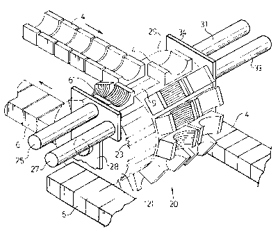
Mold transfer system 20 is well shown in Figure 3
of the drawings. Here it will be seen that a pair of
rotatable housings 21 and 29 are provided to each side of
track 3 at its rounded downstream end region where the
track guides the mold block sections away from the mold
tunnel and towards the return side of the track.
Housing 21 is provided with a plurality of mold
block carriers 23 on its outside surface. Corresponding
mold block carriers are provided on housing 29. These
transfer carriers have the same T-shaping as found in the
track carriers 9.
Mold block transfer actuators 25 and 27 are
supported by frame member 28 adjacent housing 23. Similar
actuators 31 and 33 are supported by frame member 34 at
housing 29.
Transfer system 20 is specifically designed to work
with a molding apparatus having large mold block sections
moved at a relatively slow pace. In this type of
arrangement, the actuators may be fixed in position as
shown in Figure 3.
In the operation of system 20, the mold block
sections 4 are moved to the rounded downstream end of the
CA 02271395 1999-OS-07
SJ-10489CA
- 6 -
track. As they start to pass around the end of the track,
housing 29 is rotated such that an empty carrier on housing
29 aligns side by side with the carrier on which the mold
block section on the track is mounted. From here, housing
29 is rotated at a speed consistent with that of the track
so that as each empty transfer carrier arrives to the
transfer location, i.e. the location at which it will
receive one of the mold block sections 4 it aligns with the
next track carrier.
When the empty transfer carrier aligns with the
track carrier on which the mold block section is mounted,
actuator 31, which is a pulling piston, reaches across
housing 29 and quickly pulls the slow moving mold block
section 4 off of its track carrier onto the aligned
transfer carrier. This then completes the pulling of the
mold block section 4 off of the track onto housing 29.
The removal of mold block section 4 as described
above exposes the track carrier 9. The track continues to
move the exposed carrier 9 around the end region of the
track. At the same time, housing 21 is being rotated such
that one of the carriers 23 having a replacement mold block
6 slideably mounted on that transfer carrier aligns with
the empty track carrier 9. Actuator 27, which is a piston-
like plunger, then pushes the replacement mold block
section 6 from the transfer carrier onto the track carrier.
The above operation of removal of mold block
sections 4 onto housing 29 and the replacement with the new
mold block sections 6 occurs as each successive track
mounted mold block section reaches the transfer system.
Figure 4 shows that housing 21 is fed from a train
of mold block sections 6 while the mold block sections 4
are taken off of housing 29 along a removal train for the
CA 02271395 1999-OS-07
SJ-10489CA
replaced mold block sections. This allows for a
replacement of all of the mold block sections on the track
through the feed and take away trains using only the
rotatable housings 23 and 29. Each of the feed and removal
trains is indexed to move in synchronism with the two
housings 21 and 29 in the same manner as that found with
the synchronized movement between the track and the
housings as earlier described. This allows the mold block
sections, which are mounted on slide fit carriers, to be
pushed onto the empty track carriers 23 of housing 21 at
the one side of the system and at the other side of the
system allows the replaced mold block sections 4 to be
removed from housing 29.
Although the drawings show only to the lower mold
block section track, the same thing is simultaneously
occurring at the upper mold block section track.
The description above refers to the replacement of
all of the mold block sections around the track. This
would occur when a completely new profile is to be formed
at the moving mold tunnel, e.g. when changing from a smooth
walled to a ribbed pipe. In some instances however it may
only be desirable to change the profile of the pipe at a
specific location which would not necessitate changing all
of the mold block sections. In this type of a situation,
the mold block sections taken off of the track would only
be temporarily stored at housing 29 to be replaced by mold
block sections 6. Once the mold block sections 6 have
served their purpose, they would then be moved back onto
housing 21 and the mold block sections 4 on housing 29
would be moved back onto the track. This is done by
reversing the transfer operation earlier described. For
this purpose, actuator 25 acts as a puller to pull the mold
block sections 6 onto empty carriers of housing 21 to once
again expose carrier 9 and actuator 33, which in this case,
CA 02271395 1999-OS-07
SJ-10489CA
_ g
acts as a plunger pushes the original block section 4 back
onto the exposed carrier 9.
Figure 5 shows a slightly different transfer system
generally indicated at 40. This system, like the earlier
described system, includes rotatable housings 42 and 46 to
either side of the downstream end of either of the upper
and lower tracks. Housings 42 and 46 are again provided
with slide fit transfer carriers.
The prime difference between system 40 and system
is that unlike system 20, which as noted above is used
for a heavier slow moving apparatus, system 40 is more
designed for a higher speed smaller mold block section
15 apparatus.
In system 20, the actuators are not required to
move because they can perform their pushing and pulling
functions at a single location because of the slow moving
20 speeds of the mold block sections. However, in Figure 5,
system 40 includes a plurality of mold block movers 44
which move around with housing 42 and a plurality of mold
block movers 48 which move around with housing 46.
Accordingly, the plungers, like the transfer carriers,
maintain constant synchronized alignment with the track
carriers. This enables them to push or pull the mold
blocks to and from the track onto either of the two
housings while everything is moving at a relatively high
speed.
Figure 6 shows a mold block transfer system 50
which is different from systems 40 and 20 in that unlike
the earlier described systems, system 50 both removes and
replaces the track mold blocks from one side only of the
track. This system uses a rotating housing 52 having slide
fit carriers which are fed with replacement mold block
CA 02271395 1999-OS-07
SJ-10489CA
_ g _
sections from a feed train 58. The replacement mold block
sections are pushed onto the carriers on housing 52 when
empty by means of a plunger 62.
The mold block sections which come off of the track
onto the housing 52 are then taken off of the housing by
means of a puller 64 which draws the replaced mold block
sections onto a take away train 60.
In order to carry out the transfer of mold block
sections from the track onto housing 52, the system
includes a mold block section puller 54 and a mold block
section pusher 56. The puller and the pusher, unlike all
of the above pusher and pullers, are not in dedicated
positions but rather can be moved to different positions.
They can also be controlled to move in synchronism with the
housing 52. The housing 52 is operated such that an empty
carrier on the housing aligns and moves at a corresponding
speed with a block mounted carrier of the track. Puller 54
is then operated to slide the block off of the track onto
the housing. Housing 54 must then be indexed so as to
position a replacement block thereon with the now empty
space on the track. This indexing can be achieved in a
number of manners such as stopping, reversing or
accelerating the rotation of housing 52 to the extent that
the replacement block aligns with the empty track carrier.
Once this alignment is achieved, then the rotatable housing
is once again moved in sync with the track. At this point,
pusher 56 operates to push the replacement block onto the
track.
Although all of the description above relates to
the two track pipe molding apparatus shown in the drawings
the transfer system is equally usable with a single track
system using clam shell type mold blocks.
CA 02271395 1999-OS-07
SJ-10489CA
- 10 -
It will be apparent from the description above that
the replacement of the mold block sections whether this be
done on a double or a single track apparatus, is achieved
away from the mold tunnel while the apparatus continues to
function thereby allowing continued molding in the tunnel.
In the preferred embodiment, the transfer is, as described,
performed at the downstream end of the mold tunnel, however
it could equally as well be performed at any other location
along the track travel remotely of the mold tunnel.
Although various preferred embodiments of the
present invention have been described in detail, it will be
appreciated by those skilled in the art that variations may
be made without departing from the spirit of the invention
or the scope of the appended claims.