Note: Descriptions are shown in the official language in which they were submitted.
CA 02271488 1999-OS-12
WO 98/20823 . PCT/US97/20110
1
RELEASABLE COVER ARRANGEMENT FOR
FASTENERS ON ABSORBENT ARTICLES
FIELD OF THE INVENTION
The present invention relates to absorbent articles such as sanitary napkins,
panty liners, and adult incontinence pads. More particularly, the present
invention
relates to releasable cover arrangements for the fasteners on absorbent
articles of the
foregoing type, including absorbent articles which have side wrapping elements
that
fold around or wrap the sides of a wearer's undergarments.
BACKGROUND OF THE INVENTION
Absorbent articles such as sanitary napkins, pantiliners, and incontinence
pads
are devices that are typically worn in the crotch region of an undergarment.
These
devices are designed to absorb and retain liquid and other discharges from the
human
body and to prevent body and clothing soiling. Sanitary napkins are a type of
absorbent article worn by women in a pair of panties that is normally
positioned
between the wearer's legs, adjacent to the perineal area of the body.
All manner and variety of absorbent articles configured for the absorption of
body fluids such as menses, urine, and feces are, of course, well known.
Absorbent
articles, particularly sanitary napkins, having wings or flaps are disclosed
in the
literature and are available in the marketplace. Generally, the flaps extend
laterally
from a central absorbent means and are intended to be folded around the edges
of the
wearer's panties in the crotch region. Commonly, the flaps are provided with
an
attachment means for affixing the flaps to the underside of the wearer's
panties or to
the opposing flap. The flaps are generally effective, to varying degrees in
preventing
exudates from soiling the edges of the wearer's panties.
CA 02271488 1999-OS-12
WO 98/20823 PCT/US97/20110
2
Sanitary napkins having flaps of the various types are disclosed in U. S.
Patent
4,687,478, entitled "Shaped Sanitary Napkin With Flaps," which issued to Van
Tilburg on August 18, 1987, U. S. Patent B 1 4,589,876, entitled "Sanitary
Napkin,"
which issued to Van Tilburg on May 20, 1986 and U.S. Patent 5,389,094 entitled
"Absorbent Article Having Flaps and Zones of Differential Extensibility,"
which
issued to Lavash et al. on February 14, 1995.
While there are a great many variations in the specific structural features of
absorbent articles, they are frequently presented to the consumer in the same
manner.
Essentially, the absorbent article, irrespective of what specific structural
features are
used, is packaged in a box or bag from which the consumer withdraws the ready-
to-
use articles as needed. Typically, the absorbent article comprises a fastener,
such as
a pressure-sensitive adhesive fastener on the garment-facing side of the
absorbent
article, for fastening the absorbent article to the wearer's undergarments.
The
adhesive fastener must be provided with a releasable cover strip for
preventing the
adhesive from sticking to surfaces other than the wearer's undergarments prior
to
use. The handling of absorbent articles, particularly if they are extensible,
highly
flexible, or both, is difficult because portions of the absorbent article can
fold over
and the adhesive fastener on the folded portion may stick to another portion
of the
absorbent article and not be readily releasable from the same. Further, if
such
absorbent articles are large, accurate placement of the absorbent article in
the
wearer's undergarments may be diff cult since it is hard to re-position such
articles
once they are in contact and adherence with the wearer's undergarment.
In addition, if the consumer needs only one article for later use, the
consumer
must take precautions to protect the article from soiling or contamination
from the
time it is removed from the box or bag until the article is used. This is a
particular
problem with respect to catamenial pads. For example, if a woman wishes to
carry a
catamenial pad with her for use away from home, she would have to take
precautions to ensure that the pad was not damaged or soiled when carried in
her
purse or pocket.
The protection of individual absorbent articles has been addressed in the
prior art. Bandages, for example, are commonly packaged individually and sold
to
the consumer in some sort of container which holds a convenient number of the
individually packaged articles. Catamenial pads have likewise been
individually
packaged and sold to the consumer in a container holding a convenient number
of
the individually packaged articles. U.S. Patent 2,750,033 entitled "Napkin
CA 02271488 1999-OS-12
WO 98/20823 PCT/US97/201I0
3
Packaging" which issued to J.B. Pickens on 3une 12, 1956 and U.S. Patent
3,973,567 entitled "Wrapped Sanitary Napkins" which issued to S.S. Srinivasan
et al.
on August 10, 1976 disclose examples of individually packaged sanitary
napkins.
Although these wrappers protect the enclosed sanitary napkin, they require a
quantity of wrapper material which is sufficient to cover the entire surface
area of
each napkin when it is exposed in a fully open position.
Other attempts at protecting individual absorbent articles have reduced the
quantity of wrapper material required for the protection of each absorbent
article.
Notably, U.S. Patent 4,556,146 entitled "Individually Packaged Disposable
Absorbent Article" which issued to Swanson et al. on December 3, 1985 and U.
S.
Patent 5,088,993 entitled "Sanitary Napkin .with Individual Self Wrapping
Means"
which issued to Gaur on February 18, 1992 disclose examples of individually
packaged catamenial pads which require wrapping material sufficient to cover
only
one major surface (i.e. either the body facing side or the garment facing
side) of the
sanitary napkin to allow protection of the sanitary napkin in a folded
position. These
publications, however, do not disclose arrangements for packaging absorbent
articles
having flaps.
The flaps of such sanitary napkins may be folded to conserve space during
packaging, i. e., the period between manufacture of the sanitary napkin and
its
intended first use by the wearer. At the time of the first use by the wearer,
the flaps
are usually unfolded to facilitate installation of the sanitary napkin into
the wearer's
undergarment. Consequently, when the wearer installs the sanitary napkin into
the
undergarment, the sanitary napkin is typically in the wearing position, with
the
topsheet facing the wearer, while the wearer manipulates the flaps and any
associated
protective adhesive cover (or release strip). There can be an inconvenience
associated with manipulating flaps and any associated release strip when the
flaps are
folded over the backsheet. Flaps folded over the backsheet are behind and
obscured
by the sanitary napkin, so that the flaps cannot be seen while the wearer is
attempting
to install the sanitary napkin to the undergarment. Also, flaps folded over
the
backsheet may have a tendency to become adhered to the adhesive fastener on
the
backsheet, unless held apart. Furthermore, such configuration leaves the body
facing
surface open to contamination.
Thus, a need exists for improved releasable cover arrangements for absorbent
articles of various different types and sizes. In particular, a need exists
for improved
releasable cover arrangements for absorbent articles, especially large
absorbent
CA 02271488 1999-OS-12
WO 98/20823 PCT/ITS97/20110
4
articles, having side wrapping elements. A need also exists for releasable
cover
arrangements that serve as an individual package for an absorbent article, and
in
particular, which provide a small and convenient package for a relatively
large
absorbent article. In addition, a need exists for releasable cover
arrangements for
fasteners on absorbent articles that are extensible, highly flexible, or both,
that allow
the user to more easily handle and accurately place the absorbent article in a
wearer's
undergarments.
Therefore, it is an object of the present invention to provide improved and
alternative types of releasable cover arrangements for the fasteners on
absorbent
articles.
In particular, it is an object of the present invention to provide releasable
cover arrangements for the fasteners on absorbent articles, including but not
limited
to large absorbent articles having side wrapping elements that fold or wrap
around
the sides of a wearer's undergarments.
It is another object of the present invention to provide releasable cover
arrangements that serve as an individual package for an absorbent article, and
in
particular, which provide a small and convenient package for a relatively
large
absorbent article.
It is still another object of the present invention to provide releasable
cover
arrangements for fasteners on absorbent articles that are extensible, highly
flexible, or
both, that allow the user to more easily handle and accurately place the
absorbent
article in a wearer's undergarments.
These and other objects of the present invention will be more readily
apparent when considered in reference to the following description and when
taken
in conjunction with the accompanying drawings.
SUMMARY OF THE PRESENT INVENTION
The present invention is directed to releasable cover arrangements for the
fasteners on the garment-facing side of absorbent articles such as sanitary
napkins,
panty liners, and adult incontinence pads. A number of different releasable
cover
arrangements are described herein.
In a first embodiment, the absorbent article may be of any suitable size, but
is
preferably relatively large. The absorbent article preferably has a particular
type of
CA 02271488 1999-OS-12
WO 98/20823 . PCT/US97720110
side wrapping elements that fold or wrap the sides of a wearer's
undergarments. The
absorbent article comprises a main body portion and a pair of side extensions,
or side
wrapping elements for folding around the side edges of the wearer's
undergarment.
The main body portion has a first end region, a second end region, and a
central
region disposed between the first and second end regions. The first and second
end
regions preferably comprise lobes that project laterally outward from along
each
longitudinal edge so that the main body portion is narrower in width measured
across
its central region than at its end regions. A portion of the longitudinal side
edges in
the region of the lobes, thus, defines the laterally outwardmost portion of
the main
body portion. The side wrapping elements are joined to the main body portion
at
their proximal edges and extend laterally outward to their distal edges (or
"free
ends") from at least said central region of said main body portion. The side
extensions may have a configuration wherein the maj ority of the surface area
of the
side extensions is located laterally inward of the laterally outwardmost
portion of
said main body portion.
In the first embodiment, the lobes of the sanitary napkin are folded inward
over the topsheet of the sanitary napkin to expose adhesive patches on the
lobes and
the side wrapping elements. The exposed adhesive patches are covered with a
sheet
of release paper. The sanitary napkin is also provided with a fastener on the
garment
facing side of the main body portion. The fastener on the garment facing side
of the
sanitary napkin is placed on a releasable wrapper, and the sanitary napkin and
releasable wrapper are folded about a pair of transverse axes to form an
individual
package for the sanitary napkin. This embodiment provides the advantage that
it
produces a relatively small and convenient package for a relatively large pad.
In another embodiment which is suitable for use with sanitary napkins of
many different sizes, both with and without side wrapping elements, the
adhesive
fasteners on the garment facing side of the main body portion can be covered
with
multiple release papers for ease of removal. These multiple release papers can
comprise separate pieces that have overlapping portions, or they can comprise
an
individual release paper that is perforated so that it can be separated into
more than
one piece for removal.
CA 02271488 1999-OS-12
WO 98/20823 PCT/US97/20110
6
BRIEF DESCRIPTION OF THE DRAWINGS
While the speci$cation concludes with claims particularly pointing out and
distinctly claiming the subject matter which is regarded as forming the
present
invention, it is believed that the invention will be better understood from
the
following description which is taken in conjunction with the accompanying
drawings
in which:
Fig. 1 is a top plan view of a preferred embodiment of a sanitary napkin that
may be provided with the releasable adhesive cover arrangements of the present
invention.
Fig. 2 is a cross-sectional view of the sanitary napkin shown in Fig. 1, taken
along line 2-2.
Fig. 3 is a bottom plan view of the sanitary napkin shown in Fig. 1 which
shows one,possible panty fastener pattern.
Fig. 4 is an exploded perspective view showing the assembly of the
components of the sanitary napkin shown in Fig. 1.
Fig. 4A is a top plan view of the secondary absorbent structure of the
sanitary napkin shown in the preceding drawing figures with cuts formed
therein.
Fig. 4B is a top plan view of the secondary absorbent structure in Fig. 4A,
showing how the cut portions thereof may be folded inward to form recessed
areas
for the side wrapping elements of the sanitary napkin.
Fig. 5 is a bottom plan view of the 'sanitary napkin shown in Fig. 1 which
shows another possible panty fastener pattern.
Fig. 6 is a top plan view of the sanitary napkin shown in Fig. 5 when it is
folded and placed on a releasable wrapper that will serve as an individual
package for
the sanitary' napkin.
Fig. 7 is a side view of the sanitary napkin and releasable wrapper shown in
Fig. 6 in a partially folded configuration.
Fig. 8 is a perspective view of the sanitary napkin of Fig. ? with the
releasable wrapper completely folded around the sanitary napkin to form an
individual package for the sanitary napkin.
CA 02271488 1999-OS-12
WO 98I20823 PCT/US97720110
7
Fig. 9 is a perspective view of the sanitary napkin in a wearer's panties.
Fig. 10 is a top plan view of a sanitary napkin which is provided with a
multiple piece panty fastener cover, showing one way of folding the side
wrapping
elements.
Fig. 11 is a bottom plan view of the sanitary napkin shown in Fig. 10.
Fig. 12 is a bottom plan view of a sanitary napkin having a perforated panty
fastener cover that can be separated into more than one piece for removal.
DETAILED DESCRIPTION OF THE INVENTION
The present invention relates to absorbent articles, such as sanitary napkins,
panty liners, and incontinence pads. More particularly, the present invention
relates
to releasable cover arrangements for the fasteners on absorbent articles of
the
foregoing type, including absorbent articles which have side wrapping elements
that
fold around or wrap the sides of a wearer's undergarments. FIGS. 1-3 show one
preferred embodiment of a disposable absorbent article, sanitary napkin 20. It
should
be understood that the sanitary napkin shown is merely one preferred
embodiment,
and that the present invention is not limited to use with absorbent articles
of the type
or having the specific configurations shown in the drawings.
The sanitary napkin 20 basically comprises a main body portion 22 and two
side extensions or side wrapping elements 24. The sanitary napkin 20 (and the
main
body portion thereof) has two surfaces, a liquid pervious body-contacting
surface or
"body surface" 20A and a liquid impervious garment surface 20B. The sanitary
napkin 20 is shown in FIG. 1 as viewed from its body surface 20A. The body
surface 20A is intended to be worn adjacent to the body of the wearer. The
garment
surface 20B of the sanitary napkin 20 (shown in FIG. 2) is on the opposite
side and
is intended to be placed adjacent to the wearer's undergarments when the
sanitary
napkin 20 is worn.
The sanitary napkin 20 has two centerlines, a principal longitudinal
centerline
L and a principal transverse centerline T. The term "longitudinal", as used
herein,
refers to a line, axis or direction in the plane of the sanitary napkin 20
that is
generally aligned with (e.g., approximately parallel to) a vertical plane
which bisects
a standing ~ wearer into left and right body halves when the sanitary napkin
20 is
worn. The terms "transverse" or "lateral" used herein, are interchangeable,
and refer
CA 02271488 1999-OS-12
WO 98/20823 PCT/US9?/20110
8
to a line, axis or direction which lies within the plane of the sanitary
napkin 20 that is
generally perpendicular to the longitudinal direction.
FIG. 1 shows that the main body portion 22 of the sanitary napkin 20
comprises the portion of the sanitary napkin without the side wrapping
elements 24.
The main body portion 22 has two spaced apart longitudinal edges 26, two
spaced
apart transverse or end edges (or "ends") 28, which together form the
periphery 30
of the main body portion of the sanitary napkin 20. The main body portion 22
also
has two end regions, which are designated first end region 32 and second end
region
34. A central region 36 is disposed between the end regions 32 and 34. The end
regions 32 ~ and 34 extend outwardly $om the edges of the central region 36
about
1 /8 to about 1 /3 of the length of the main body portion. A detailed
description of the
central region and two end regions for a sanitary napkin is contained in U. S.
Patent
4,690,680 issued to Higgins on September 1, 1987.
The main body portion 22 of the sanitary napkin 20 is preferably hourglass
shaped or dog bone shaped. The first and second end regions 32 and 34, of the
main
body portion 22 preferably comprise lobes 38 that extend laterally outward at
each
longitudinal edge 26 of the main body portion so that the main body portion 22
is
narrower in width when measured across the central region 36 than at its end
regions
32 and 34. The outermost edges of the lobes 38, thus define portions of the
longitudinal side edges 26 of the main body portion 22. A portion of the
longitudinal
side edges 26 in the region of the lobes 38 will also typically define the
laterally
outwardmost portion 40 of the main body portion 22.
The main body portion 22 of the sanitary napkin 20 can be of any thickness,
including relatively thick, intermediate (or moderate) thickness, relatively
thin, or
even very thin. The embodiment of the sanitary napkin 20 shown in Figures 1-3
of
the drawings is intended to be an example of a moderately thick sanitary
napkin. In
this embodiment, however, the main body portion 22 is generally thinner in the
end
regions 32 and 34 than in the central region 36 so that it will be more
comfortable
and discrete than if it was uniformly moderately thick. The main body portion
22 of
the sanitary napkin is also preferably embossed with channels 42 such as those
described in U.S. Patents 5,234,422 and 5,308,346 issued to Speller, et al.
The sanitary napkin 20 shown in FIG. 1 can be of any suitable size.
Preferably, the sanitary napkin 20 is a size sufficient to allow the side
wrapping
elements 24 to fold around the side edges of the wearer's panties as described
in
CA 02271488 1999-OS-12
WO 98I20823 PCT/US97/20110
9
greater detail herein. The sanitary napkin 20, and the main body portion 22
thereof,
are preferably also relatively large in size so that they are able to cover
the maximum
area of the wearer's panties to reduce or eliminate soiling of the same by the
wearer's
bodily fluids. In one preferred embodiment, the main body portion 22 of the
sanitary
napkin 20 is about 3.25 inches (8.26 cm) wide at its narrowest point. The
overall
sanitary napkin 20 in such an embodiment is approximately 14.75 inches (37. S
cm) in
length measured along the longitudinal centerline L, and about 6.25 inches
(about 16
cm) in width (measured between the distal edges of the side wrapping
elements). In
another embodiment, the width of the sanitary napkin 20 is the same, but the
length
ranges fi-om about 31.7 cm to about 34.5 cm.
FIG. 2 shows the individual components of the main body portion 22 of the
sanitary napkin 20. The main body portion 22 generally comprises at least
three
primary components. These include a liquid pervious topsheet 44, a liquid
impervious backsheet 46, and an overall absorbent portion (or "absorbent
core") 48
positioned between the topsheet 44 and the backsheet 46. The absorbent core 48
preferably comprises a main (or primary) absorbent structure (or absorbent
component) 50 and a secondary absorbent structure (or absorbent component) 52.
The main absorbent component 50 is preferably roughly centered along the
principal
longitudinal and transverse centerlines L and T. In alternative embodiments,
the main
absorbent component 50 could be shifted longitudinally forward or backward
relative
to the transverse centerline T. Suitable materials for the various components
of the
sanitary napkin 20 shown in FIG. 2 are described below.
In a particularly preferred embodiment, the topsheet 44 comprises a
composite or "hybrid" topsheet structure. The hybrid topsheet 44 generally
comprises a longitudinally oriented central zone 54 and longitudinal side
regions 56
located laterally outboard of the central zone 54. The hybrid topsheet 44
structure
preferably comprises an apertured thermoplastic film 58 in the central zone 54
of the
hybrid topsheet structure 44 and a tactilely-pleasing outer covering that
forms the
longitudinal side regions 56 of the topsheet. Such a topsheet 44 is useful for
improving the skin feel and comfort of topsheets made of apertured plastic
films. In
particular, such a topsheet 44 reduces the tendency that some people find for
apertured plastic filins to feel hot, sweaty, and sticky. This is especially
useful in the
case of relatively large absorbent articles such as the one shown in FIGS. I-3
where
there is a large portion of the topsheet 44 which is in contact with the
wearer's body.
Hybrid topsheet structures (though not the particularly preferred hybrid
topsheet
used herein) are described generally in U. S. Patent 4,687,478 issued to Van
Tilburg
CA 02271488 1999-OS-12
WO 98I20823 PCT/L1S97/20110
and in PCT Publication No. 93/09744 assigned to The Procter & Gamble Company
which published May 27, 1993, in the name of Sugahara.
In the particularly preferred embodiment shown in FIGS. 1-3) the apertured
thermoplastic film 58 of the hybrid topsheet 44 preferably extends the full
width of
the sanitary napkin 20. The apertured thermoplastic film 58 preferably
comprises an
apertured film sold on sanitary napkins by The Procter & Gamble Company of
Cincinnati, Ohio under the trademark DRI-WEAVE, which is manufactured under
U.S. Patent 4,342,314 issued to Radel, et al. on August 3, 1982 and U.S.
Patent
4,463,045 issued to Ahr, et al. on July 31, 1984. In preferred embodiments,
the
apertured thermoplastic film 58 is rendered hydrophilic so that liquids will
transfer
through the apertured thermoplastic film faster. This will diminish the
likelihood that
body exudates will flow off the apertured thermoplastic film 58 rather than
being
drawn through the apertured thermoplastic film and being absorbed by the
absorbent
core 48. The apertured thermoplastic film 58 can be rendered hydrophilic by
treating
it with surfactants. Suitable methods of applying surfactants are described in
U.S.
Patents 4,950,254 and 5,009,b53 issued to Osborn. Preferably, surfactant is
incorporated into the resin used to make the apertured film.
The tactilely-pleasing outer covering 60 can be any suitable type of material
(or web of material) that is liquid pervious and is more comfortable to the
wearer's
skin than the apertured film 58 that forms the central zone 54 of the
topsheet.
Suitable materials include apertured films with a less plastic-like feel and
nonwoven
materials. Suitable less-plastic like apertured films include the apertured
film
described in U.S. Patent 4,629,643 entitled "Microapertured Polymeric Web
Exhibiting Soft and Silky Tactile Impression" issued to Curro, et al. on
December
16, 1986, and the hydroformed films made by the method described in U. S.
Patent
4,695,422 entitled "Production of Formed Material by Solid-State Formation
With
I~gh-Pressure Liquid Stream" issued to Curro, et al. on September 22, 1987.
Suitable nonwoven materials can be made from natural fibers (e. g., wood or
cotton
fibers), synthetic fibers (e.g., polyester, polyethylene, or polypropylene
fibers), or a
combination of natural and synthetic fibers. Such a nonwoven outer covering
can be
made Iby a number of manufacturing techniques. For example, a nonwoven outer
covering can be spunbonded, carded, wet-laid, meltblown, hydroentangled, to
name
a few possible types of processes.
In the embodiment shown in FIGS. 1-3, the outer covering 60 is a nonwoven
material (or nonwoven web). The nonwoven material 60, as shown in FIG. 2, has
a
CA 02271488 1999-OS-12
WO 98/20823 PCT/US97/20110
11
body surface 60A and a garment facing surface 60B that are separated from one
another by an intermediate portion 60C. The nonwoven material 60 can comprise
any suitable type of nonwoven material described above. Preferably, in the
embodiment shown in FIGS. 1-3, the nonwoven material 60 comprises a 23 gsm
spunbond polyethylene nonwoven material known as a COROLIND nonwoven,
available from Corovin GmbH of Peine, Germany.
The spunbond polyethylene nonwoven material is preferably treated so that
the body surface 60A of the nonwoven material exhibits a surface energy that
is less
than the surface energy of the intermediate portion 60C of the nonwoven
material.
That is, there is a surface energy gradient between these portions of the
nonwoven
material. The term "surface energy" as used herein, refers to the energy
required to
separate a liquid from a solid surface (e.g., a film or, in this case, a
fiber). In a
particularly preferred embodiment, the surface of the treated nonwoven
material also
exhibits a plurality of regions of comparatively low surface energy which
define
surface energy gradients where they interface with higher surface energy web
surfaces. Webs having such surface energy gradients are described in greater
detail
in U.S. Patent Application Serial No. O8/442,935, filed on May 31, 1995 in the
name
of Ouellette, et al. (PCT Publication WO 96I00548 published January 11, 199b).
The treatment of the web to form a surface energy gradient, may be referred to
herein as an "SEG" treatment for brevity. The SEG treatment is intended to
reduce
the hydrophilicity of the nonwoven material 60 and improve the stain masking
and
rewet properties of the nonwoven material. The nonwoven material 60 will have
a
reduced tendency to hold liquids at its surface, and liquids, such as menses,
which
are deposited on the nonwoven material will be better able to pass through the
nonwoven material 60 to the underlying absorbent components. As a result, the
liquid handling properties and masking properties of the nonwoven material 60
will
more closely approach those of the apertured film 58.
The SEG treatment can be applied either before or after the components of
the hybrid topsheet are assembled. However, the SEG treatment is preferably
applied before assembly of the components so that it can be applied more
precisely.
The SEG treatment is preferably accomplished by applying a suitable surface
treatment to the nonwoven web 60. A suitable surface treatment is a silicone
release
coating from Dow Corning of Midland, Michigan known as SYL-OFF 7677 to
which a crosslinker known as SYL-OFF 7048 is added in proportions by weight of
100 parts to 10 parts, respectively. Another suitable surface treatment is a
coating of
a UV curable silicone comprising a blend of two silicones commercially
available
CA 02271488 1999-OS-12
WO 98I20823 PCT/US97%20110
12
from General Electric Company, Silicone Products Division of Waterford, NY,
under the designations UV 9300 and UV 9380C-D1, in proportions by weight of
100
parts to 2.5 parts, respectively. The surface treatments may be applied to the
body
surface 60A of the nonwoven web by techniques known in the art such as screen
printing, grawre printing, spraying, dip coating, etc.
The nonwoven material 60 is preferably coated with silicone on the wearer-
contacting surface at a basis weight of 1 gram per square meter. The basis
weight of
the SYL-OFF material is determined by subtracting the basis weight of the
nonwoven material in an uncoated condition {grams per square mater) from the
basis
weight (grams per square mater) of the coated nonwoven material.
In addition to the liquid handling characteristics supplied by SEG treating
the
nonwoven component 60 of the hybrid topsheet 44, the treatment has also been
found to improve the tear and tensile strength of the nonwoven material 60.
The
SEG treatment is believed to reduce the modulus of elasticity of the fiber
network in
the nonwoven material, making it softer, more flexible, and more drapable.
This is
useful when subsequent mechanical operations, such as the ring rolling process
described below, will be performed on this portion of the hybrid topsheet 44
in order
to provide the more flexible and extensible regions 84 shown in the drawings.
The nonwoven material 60 is preferably secured in at least partial contacting
relation with the apertured thermoplastic film component 58 of the hybrid
topsheet
44. The nonwoven material 60 can be maintained in contact with the apertured
thermoplastic film 58 by fusion bonding, adhesive attachment of the layers, or
by-any
other suitable securement means known in the art. Fusion bonding includes heat
and/or pressure bonding, ultrasonic bonding, and the like. The two layers can
be
continuously, partially, or intermittently bonded together. The bonding of the
nonwoven material 60 to the apertured thermoplastic film 58 can prevent the
nonwoven material 60 from being torn or from rolling back onto itself at its
inside
edges 62, v~rhich would create an uncomfortable feeling. In a preferred
embodiment,
the nonwoven material 60 and the apertured thermoplastic film layer 58 are
adhesively bonded together using a spiral pattern of adhesives and are also
spot-
bonded with a plurality of small spaced apart circular fusion bonds 64.
Various alternative embodiments of the hybrid topsheet 44 are possible. In
alternative embodiments of the hybrid topsheet, the nonwoven material (or
other
tactilely-pleasing outer covering) can be of a different color from the
apertured film
CA 02271488 1999-05-12
WO 98/20823 . PCT/US97%20110
13
58. This can be used to provide the product with the appearance of a barrier
at the
boundary of the apertured film 58 and the nonwoven material (or other
tactilely-
pleasing outer covering) 60. Examples of suitable colors for the nonwoven
material
(or other tactilely-pleasing outer covering) 60 would be pink, peach, light
blue, or
lavender. Preferably, however, the nonwoven material (or other tactilely-
pleasing
outer covering) 60 is white.
The absorbent core 48, as noted above, preferably comprises a primary
absorbent structure 50. The primary absorbent structure 50 lies beneath the
hybrid
topsheet 44. The primary absorbent structure 50 serves as the main absorbent
component of the sanitary napkin 20. The primary absorbent structure 50
absorbs
the bodily exudates that are deposited directly on the sanitary napkin in the
area of
typical liquid deposition. The primary absorbent structure 50 can be any
suitable
type of absorbent structure. Suitable absorbent structures are described in
the
patents which are incorporated herein by reference. In the prefeiTed
embodiment,
shown in FIGS. 1-4, the primary absorbent structure 50 comprises an oval or
race-
track shaped airfelt absorbent component similar to the absorbent core
described in
U.S. Patents 5,234,422 and 5,308,346 issued to Sneller, et al. As shown in
FIG. 4,
the primary absorbent structure 50 is "profiled" so that it is provided with a
central
region which is thicker than its edges and ends. The primary absorbent
structure 50
can be oriented so that the profiled central region is facing upward as shown
in FIG.
4, or downward.
The secondary absorbent structure 52 serves as back-up absorbent for the
primary absorbent structure 50. The secondary absorbent structure 52 is
intended to
absorb and contain bodily exudates that are not deposited directly on the
primary
absorbent structure .50. The secondary absorbent structure 32 can also absorb
exudates that flow across the topsheet beyond the boundaries of the primary
absorbent structure, or which overload any portions of the primary absorbent
structure 50. In the embodiment shown in FIGS. 1-4, the secondary absorbent
structure 52 lies beneath the primary absorbent structure S0. The secondary
absorbent structure 50 can comprise any type of absorbent material that is
suitable
for these purposes. In the preferred embodiment shown in FIGS. 1-4, the
secondary
absorbent structure 52 comprises a high capacity thermally bonded airlaid
nonwoven
material fabricated from a blend of cellulose and bicomponent fibers (referred
to as
"TBAL" material for brevity). The TBAL material preferably comprises a
homogeneous blend of about 55% Flint River fluff (cellulose), 34% Nalco 1180
absorbent gelling material particles obtained from Nalco of Naperville, IL,
and 11
CA 02271488 1999-OS-12
WO 98/20823 . PCT/US97I20110
14
DANKLON ES-C 3.3 dtex x 6 mm bicomponent fibers obtained from Dan Web of
Aarhus, Denmark. The TEAL material is formed into a web having a basis weight
of
about 210 grams/m2, and a caliper of about 1.6 mm measured under a load of
about
1.2 g/cm2.
The secondary absorbent structure 52 is preferably covered by an optional
intermediate acquisition component 66. The optional intermediate acquisition
component 66 serves to drain liquids through the topsheet 44 and provide void
volume so that the underlying TBAL layer (which has high storage capacity, but
relatively slow rate of absorbency) will have time to absorb bodily exudates
deposited thereon. The optional acquisition component 66 is, thus, more
important
for use with the portion of the secondary absorbent structure 52 that lies
outside the
boundaries of the primary absorbent structure 50. The acquisition component 66
can
comprise any material which is suitable for the aforementioned purposes. In
the
preferred embodiment shown in FIGS. 1-4, the acquisition component 66
comprises
a layer of an 18 g/yd2 (21.5 g/m2) spun bonded polypropylene nonwoven material
known as CELESTR'A available from Fiberweb, North America of Simpsonville, SC,
which is embossed with the pattern described in U.S. Patent 4,781,7l0 issued
to
Megison, et al. on November 1, 1988. The acquisition component is preferably
of
the same shape and size as the TBAL layer. . The CELESTRA material is
preferably
bonded to the overlying component (which will either be the primary absorbent
structure 50 or, for the portions of the acquisition component 66 that lie
outboard of
the primary absorbent structure, the underside of the hybrid topsheet 44), but
is
unbonded to the TBAL layer.
In an alternative embodiment, the positions of the absorbent materials can be
reversed so that the TB,AL material overlies the airfelt component. In such a
case,
the TBAL layer could be considered to comprise the primary absorbent
structure,
and the airfelt component could be considered to comprise a secondary
absorbent
structure that provides a portion of the sanitary napkin 20 with additional
bulk. In
other alternative embodiments, such a bulking material can comprise any other
suitable absorbent materials, or even nonabsorbent materials. One suitable
absorbent
material comprises a carded or airlaid thermal air through bonded nonwoven
material
comprised of bicomponent fibers having an eccentric cross-section that has a
wetting
agent included in the sheath resin and a permanent wetting agent applied to
the
surface which is described in greater detail in U. S . Patent 5,231,122 issued
to
Palumbo, et al. Suitable non-absorbent materials can comprise closed cell
foams,
polyurethane foams, and high loft nonwoven webs comprised of synthetic fibers.
CA 02271488 1999-OS-12
WO 98/20823 PCT/US97%20110
The backsheet 46 prevents the exudates absorbed by and contained in the
components of the absorbent core 48 from wetting articles which contact the
sanitary
napkin 20 such as the wearer's pants, pajamas and undergarments. The backsheet
46
should be flexible and impervious to liquids (e.g. menses and/or urine). The
backsheet 46 may comprise a woven or nonwoven material, polymeric films such
as
thermoplastic films of polyethylene or polypropylene, or composite materials.
Preferably, the backsheet 46 comprises a polyethylene film having a thickness
of
from about 0.012 mm (0.5 mil) to about 0.051 mm (2.0 mils). An exemplary
polyethylene films is a product known as microflex 1401 manufactured by The
Clopay Corporation of Cincinnati, Ohio.
The topsheet 44, the backsheet 46, and the absorbent core 48 may be
assembled in a variety of configurations known in the art (including so called
"sandwich" products and "tube" products). In addition to the description
provided
herein, several preferred sanitary napkin configurations and features that the
sanitary
napkin can be provided with are described generally in U. S. Patent 4,32
Z,924,
"Bordered Disposable Absorbent Article" issued to Ahr on March 30, 1982; U.S.
Patent 4,42S,130, "Compound Sanitary Napkin" issued to DesMarais on January
10,
1984; U.S. Patents 4,950,264 and 5,009,653, both entitled "Thin, Flexible
Sanitary
Napkin" issued to Osborn on August 21, 1990 and April 23, 199l, respectively;
and
the aforementioned patent applications issued to Sneller, et al. The main body
portion 22 of the sanitary napkin may also be comprised of one or more
extensible
components and may either have an overall extensibility, or regions with
extensibility, such as those sanitary napkins, and the like described in U. S.
Patent
Application Serial No. 07/915,133 filed July 23, 1992, in the name of Osborn,
et al.
(PCT Publication No. WO 93I01785, published February 4, I993 ), now pending in
the form of allowed continuation Application Serial No. 08/503,895, filed on
July 18,
1995; and U. S. Patent Application Serial No. 07/915,284 filed July 23, 1992,
in the
name of Osborn, et al. (PCT Publication No. 93/01786, published February 4,
1993),
now pending in the form of allowed divisional Application Serial No.
08l476,238,
filed on June 7, 1995.
The sanitary napkin 20 shown in FIGS. 2 and 4, is preferably assembled in a
sandwich construction in which the topsheet 44 and the backsheet 46 have
dimensions that are generally larger than those of the absorbent core 48. FIG.
4
shows the assembly of the components of the sanitary napkin 20. As shown in
FIG
4, the hybrid topsheet 44 is joined to the primary absorbent structure 50 in
the region
of the sanitary napkin that includes the primary absorbent structure 50. The
hybrid
CA 02271488 1999-05-12
WO 98/20823 PCT/US97/20110
16 .
topsheet 44 is joined to the optional intermediate acquisition component 66 in
the
region of the sanitary napkin that lies outboard of the primary absorbent
structure 50.
The hybrid topsheet 44 is joined to the backsheet 46 in the region of the
sanitary
napkin that lies outboard of the absorbent core 48. Preferably, the hybrid
topsheet 44
is joined to these components by a core bonding adhesive that is applied in a
spiral
pattern. The secondary absorbent structure 52 is preferably joined to the
backsheet
46. Preferably, the secondary absorbent structure 52 and the backsheet 46 are
joined
using a core integrity adhesive 70 applied in a plurality of strips of
adhesive, each of
which comprises spirals of adhesive. Exemplary means for joining these
components
of the sanitary napkin 20 comprises several lines of adhesive filaments
swirled into a
spiral pattern such as illustrated by the apparatus and method shown in U.S.
Patent
3,911,1?3 issued to Sprague, Jr. on October 7, 1975; U.S. Patent 4,785,996
issued
to Ziecker, et al. on November 22, 1978; and U. S. Patent 4, 842,666 issued to
Werenicz on June 27, 1989. The core integrity adhesive 70 can be applied over
the
entire garment facing side of the secondary absorbent structure 52, over the
whole
product width (including the extensions of the backsheet that will lie beyond
the
edges of the secondary absorbent structure) or any portion thereof.
Preferably, the
core integrity adhesive 70 is applied to the entire interface between the
garment
facing side ~of the secondary absorbent structure 52 and the backsheet 46.
In addition to joining the faces of the components of the sanitary napkin 20
as
described above, FIG. 1 shows that the topsheet 44 and backsheet 46 are joined
together to form a seam 72 along at least portions of the periphery 30 of the
main
body portion. The seam 72 can be formed by any means commonly used in the art
for this purpose, such as gluing, crimping, or fusing. In the preferred
embodiment
shown in FIG. 1, the seam 72 is formed by a plurality of rectangular spaced
apart
fusion bonds 72A (only a few of which are shown for simplicity). In addition,
longitudinally oriented fusion bonds 72B are applied to the central region of
the side
wrapping elements 24 along the distal edge 76 of the same. It is to be
understood
that the embodiment illustrated in the drawings is only one possible
embodiment,
albeit a preferred one. Other possible embodiments include one in which an
absorbent core 48 is essentially completely wrapped with a topsheet before it
is
placed on a backsheet. The main body portion 22 can also comprise an absorbent
core which possesses su~cient integrity to stand alone and is liquid pervious
on one
surface while the other surface has been treated to render it liquid
impervious.
The sanitary napkin 20 shown in the drawings comprises a pair of side
extensions (or "side wrapping elements") 24 for folding around the side edges
of the
CA 02271488 1999-05-12
WO 98/20823 PCT/US97/20110
17
wearer's panties (or other undergarment). As shown in FIG. 1, the main body
portion 22 is narrower in width measured across its central region 36 than at
its end
regions 32 and 34. The side wrapping elements 24 extend from at least the
central
region 36 of the main body portion 22. The side wrapping elements 24 are
preferably configured so that the majority of the surface area of the side
wrapping
elements 24 is located laterally inward of the laterally outwardmost portion
40 of the
main body portion 22. The sanitary napkin 20 can thus be thought of as having
"internal flaps" that can fold around a wearer's undergarments.
The side wrapping elements 24 each have a proximal edge 74 and a distal edge
76. In the embodiment shown in the drawings, the proximal edges 74 of the side
wrapping elements 24 are preferably concave (relative to the distal edges 76).
The
distal edges 76 of the side wrapping elements 24 are preferably approximately
parallel to the longitudinal centerline L. The sanitary napkin 20 shown in the
drawings may be thought of as having "internal flaps" because the side
wrapping
elements 24 are longitudinally inboard of the outermost edges of the lobes 3 8
of the
main body portion 22 and the distal edges 76 of the side wrapping elements 24
preferably do not extend appreciably laterally outward beyond the outermost
edges
of the lobes 38 of the main body portion 22 of the sanitary napkin 20 and any
peripheral flange, such as seam 72 around the same.
The side wrapping elements 24 are joined to the main body portion 22 at their
proximal edges 74. The term "joined", as used herein, encompasses
configurations in
which an element is directly secured to another element by axing the element
directly to the other element; configurations in which the element is
indirectly
secured to the other element by affixing the element to intermediate members)
which in turn is affixed to the other element; and configurations in which one
element
is integral with another element, i.e., one element is essentially part of the
other
element.
The side wrapping elements 24 on the embodiment shown in FIGS. 1-3 are
preferably integral with the main body portion 22 of the sanitary napkin. In
such a
case, the topsheet 44 may form a portion of the side wrapping elements 24 and
the
backsheet 46 may also form a portion thereof. For example, the topsheet 44 may
form the body-facing surface of both the side wrapping elements 24 and the
main
body portion 22, and the backsheet 40 may form the garment-facing surface of
the
same. It is also possible for the absorbent material of the sanitary napkin 20
to
extend into the side wrapping elements 24, as described in greater detail for
the side
CA 02271488 1999-OS-12
WO 98I20823 PCT/US97/20110
18
flaps of the sanitary napkin in U.S. Patent 4,917,697. In alternative
embodiments,
the side wrapping elements 24 may be comprised of separate pieces of material
or
elements which are attached to the main body portion 22. The side wrapping
elements 24 may be joined in any of the manners that the side flaps are joined
to the
absorbent article described in U. S. Patent 5,389,094 issued to Lavash, et al.
on
February 14, 1995. When the side wrapping elements 24 comprise separate
elements, they can be joined to the main body portion 22 by any techniques
known to
those skilled in the art. Such techniques include, but are not limited to
adhesives,
heat and/or pressure, ultrasonics, etc.
The side wrapping elements 24, whether they are integral with the main body
portion or separate elements attached thereto, are each associated with main
body
portion 22 along a juncture. The juncture is typically a longitudinally-
oriented (or
"longitudinal") juncture, such as line of juncture 78. As used herein, the
terms
"juncture" (or "line of juncture") refer to regions where the side wrapping
elements
24 extend from or are joined to the main body portion 22. The junctures 78 can
be
any of various curved or straight lines, but they are not limited to Lines.
Thus, the
junctures can comprise regions, flanges, strips, intermittent lines, and the
like. In the
sanitary napkin 20 illustrated in FIG. 1, line of juncture 78 is a generally
longitudinally oriented region that is concave relative to the distal edges 76
of the
side wrapping elements. When the side wrapping elements 24 are integral with
the
main body portion 22, the lines of juncture 78 may represent lines of
demarcation
between the main body portion 22 and the side wrapping elements 24, although
it is
not necessary that there be a precise line of demarcation.
The side wrapping elements 24 are preferably more flexible (that is, less
stiff]
than those parts of the~main body portion that form the longitudinal side
edges 26 of
the main body portion. The difference in stiffness along the longitudinal side
edges
26 of the lain body portion 22 provides the sanitary napkin 20 with a curved
hinge
line about which the side wrapping elements 24 may fold.
As shown in Figure 1, each side wrapping element 24 is divided into a front
half 80, and a back half 82 by a side wrapping element transverse centerline T
1. The
side wrapping element transverse centerline T 1 may coincide with the
principal
transverse centerline T of the sanitary napkin, but this is not absolutely
required. In
other embodiments where the main body portion 22 is not symmetrical along its
length, the side wrapping elements 24 may be located more toward one end of
the
main body portion, and the side wrapping element transverse centerline T 1
may,
CA 02271488 1999-OS-12
WO 98/20823 PCT/tTS97I20110
19
thus, be offset either to the front or to the rear of the principal transverse
centerline
T.
The side wrapping elements 24 are provided with weakened regions 84 that
are more flexible than the adjacent regions 86 of the side wrapping elements.
The
weakened regions 84 are located so that on each side wrapping element 24, at
least
one weakened region, or portion thereof, lies on each side of the side
wrapping
element transverse centerline T 1. The weakened regions 84 are preferably at
least
partially disposed longitudinally away from the flap transverse centerline T 1
in both
directions. (Thus, the weakened regions 84 may be described as being
longitudinally
"remote" from the side wrapping element transverse centerline T 1 ). In the
most
preferred case (as will be subsequently described in Beater detail), the
weakened
regions 84 are located along a portion of the fold line where the side
wrapping
elements 24 are folded around the wearer's panty crotch. The fold line will
typically
be located along or adjacent the longitudinal juncture 78 of each side
wrapping
element 24. Since the terms "portions", "zones", and "regions", as used
herein, refer
to general areas, the weakened regions 84 are, thus, not limited to points
which lie
precisely on the line of juncture 78. Typically, they will include both those
points
which lie on the lines of juncture 78 as well as the surrounding areas of the
sanitary
napkin 20 which include the aforementioned fold lines). The longitudinal
junctures,
thus, may merely serve as approximations for the location of the weakened
regions
84.
The weakened regions 84 are preferably also extensible. The weakened
regions 84 may, thus, he thought of as comprising zones of differential
extensibility
(or "zones of extensibility"). The term "zones of differential extensibility",
as used
herein, refers to a portion of the side wrapping element 24 which is capable
of
extending a differing amount (preferably a Beater amount), than adjacent
regions 86
of the side wrapping element 24. The extensibility of the weakened regions 84
relieves the stresses which develop in the side wrapping elements 24 when they
are
folded around the sides of the wearer's panty crotch.
The weakened regions 84 are preferably primarily extensible generally outward
in the transverse direction. As used herein, the phrase "generally in the
transverse
direction" means that the extensibility has a transverse component. All of the
extension, however, need not be exactly parallel to the principal transverse
centerline, T, of the sanitary napkin. For example, in the embodiment shown in
FIG.
1, the weakened regions 84 are extensible in a direction between the
longitudinal and
CA 02271488 1999-OS-12
WO 98/20823 PCT/US97120110
transverse directions. The extensibility of the weakened regions 84, however,
is
preferably oriented more in the transverse direction than in the longitudinal
direction
so that it is still generally in the transverse direction. It is possible,
however, that in
other embodiments, the extensibility of the weakened regions 84 can be
oriented
more in the longitudinal direction than the transverse direction, or even
entirely in the
longitudinal direction.
The weakened regions 84 can comprise any structure that is more flexible
and extensible than the adjacent regions 86 of the side wrapping elements 24.
The
weakened regions 84 (although shown in FIGS. 1-3 as only being part of the
side
wrapping elements 24), can comprise portions of the main body portion 22,
portions
of the side wrapping elements 24, or both. Suitable structures for the
weakened
regions 84 include, but are not limited to zones of material that are
mechanically
strained, corrugated, "ring rolled" (the term "ring rolled" refers to a
straining/activation achieved by feeding a material through intermeshing
corrugated
rolls), folded, formed into a Structural Elastic-Like Film, or pleated, or
joined along
a curved juncture. Structural Elastic-Like Film structures are described in
greater
detail in U. S. Patent 5, 518, 801 entitled "Web Materials Exhibiting Elastic-
Like
Behavior", issued to Chappell, et al. on May 21, 1996, and in U.S. Patent
Application Serial No. 08/ 124,180 filed by Mansfield, et al. (PCT Publication
No.
WO 94/ 10200). Examples of sanitary napkins having flaps and zones of
differential
extensibility are further described in U.S. Patent 5,354,400 issued to Lavash,
et al.
on October 11, 1994, and U.S. Patent 5,389,094 issued to Lavash, et al. on
February
14, 1995. Other, but less preferred, examples of structures that can provide
the side
wrapping elements 24 with a degree of flexibility and extensibility are the
notches
shown in FIG. 5 of U:S. Patent B 1 4,589,876 issued to Van Tilburg and the
stress
relief means described in U.S. Patent 4,917,697 issued to Osborn, et al.
The sanitary napkin 20 shown in FIGS. 1-3 has side wrapping elements 24 that
have been provided with weakened regions 84 by ring rolling the desired
regions of
the side wrapping elements 24. The weakened regions 84 can be ring rolled in
accordance with methods described in U. S. Patent 4,107,364 issued to Sisson
on
August 15, 1978, U.S. Patent 4,834,741 issued to Sabee on May 30, 1989, U.S.
Patent 5,143,679 issued to Gerald M. Weber, et al. on September l, 1992, U. S.
Patent 5,156,793 issued to Kenneth B. Buell, et al. on October 20, 1992, and
U.S.
Patent 5,167,897 issued to Gerald M. Weber, et al. on December 1, 1992. The
ring
rolling forms corrugations in the weakened regions 84. The corrugations
comprise
ridges and valleys that are defined by fold lines 88. The fold lines 88 may
form any
CA 02271488 1999-OS-12
WO 98/20823 PCT/US97/~0110
21
angle desired relative to the principal longitudinal centerline L. In the
preferred
embodiment shown in FIGS. 1-3, the fold lines 88 form an angle of between
about
40° - 45° with the principal longitudinal centerline L. This
will provide the desired
direction of extensibility.
The side wrapping elements 24 are sufficiently flexible and are sized and
configured so that they are capable of folding around the side edges of a
crotch
region of a wearer's undergarment. In order to be capable of folding around
the
sides of an undergarment, the side wrapping elements 24 must be of a certain
minimum size. Otherwise, the adjacent stiffer portions of the sanitary napkin
20,
such as the lobes 38, of the main body portion 22, to which the side wrapping
elements 24 are joined, will restrict and prevent the side wrapping elements
24 from
folding. The side wrapping elements 24 preferably range in size from about 2
cm in
width (transverse direction from their proximal edge to their distal edge) and
about
16.5 cm in length (longitudinal direction) up to about 4.5 or 5 cm in width
and about
23.5 cm in length. The side wrapping elements 24 in the embodiment shown in
FIGS. 1-3 are preferably about 2 inches (about S cm) in width from their
proximal
edge to their distal edge, and about 8 inches (about 20 cm) in length. The
side
wrapping elements 24 shown in the drawings preferably also measure greater
than or
equal to about 160 mm, more preferably greater than or equal to about 170 mm,
more preferably greater than or equal to about 180 mm, more preferably still
greater
than or equal to about 190 mm, and most preferably greater than or equal to
about
200 mm along their curvilinear proximal edge.
The enhanced flexibility and extensibility of the weakened regions 84, along
with the difference in flexibility between the side wrapping elements 24 and
longitudinal side edges 26 of the main body portion 22, allows the side
wrapping
elements 24 to fold smoothly around the edges of the wearer's panties. If the
longitudinal side edges 26 of the main body portion 22 are approximately the
same
size and shape as the side edges of the wearer's panties, the side wrapping
elements
24, in a most preferred embodiment, can fold on a curvilinear line virtually
exactly
along the side edges of the wearer's panties. Preferably, the side wrapping
elements
24 fold at least along a generally curvilinear line that lies at least
generally along the
side edges of the wearer's panties. The side wrapping elements 24 can, if
desired,
bend through an angle of 180 degrees, and be attached to the underside of the
wearer's panties. The fact that the side wrapping elements 24 can fold along a
curvilinear line, allows the side wrapping elements to form a flat fold along
the length
of the edges of the wearer's panties. This reduces the tendency for the side
wrapping
CA 02271488 1999-OS-12
WO 98/20823 . PCT/US97/20110
22
elements to bunch longitudinally inward in a manner that would reduce the area
of
the wearer's panties the side wrapping elements 24 are able to cover. It also
reduces
the tendency for the ends of the main body portion along the longitudinal side
edges
thereof to become detached from the wearer's panties and lift up and fold over
onto
the topsheet. It further substantially reduces, if not eliminates, any
tendency for the
side wrapping elements 24 to become unattached to the underside of the
wearer's
panties (or for the fastener on the side wrapping elements to "pop off' from
their
attachment with the underside of the panties).
The side wrapping elements 24 can be formed in any suitable manner. For
example, in one version of the embodiment shown in FIGS. 1-3, areas for the
side
wrapping elements 24 can be formed by cutting the secondary absorbent
structure 52
at certain places and then folding portions of the secondary absorbent
structure
inward over the central region of the same. As shown in FIG. 4A, a pair of
curvilinear slits 90 are formed in the secondary absorbent structure 52. The
slits 90
extend from points on the longitudinal side edges of the secondary absorbent.
structure 52 toward, but not all the way to, the transverse centerline
thereof. The
outer portions 92 of the secondary absorbent structure that are outboard of
the slits
are then folded inward as shown in Fig. 4B. This leaves a cut out area having
a
curvilinear edge 93. The curvilinear edge 93 is preferably at least about 160
mm
long and the outer portion 92 formed by the cutting is preferably about 2
inches in
width at its widest portion and about 8 inches long measured in the
longitudinal
direction. The portions 92 of the secondary absorbent structure that are
folded can
be folded either over or under the central region of the secondary absorbent
structure
52. These outer portions 92 can also be folded either over or under the
primary
absorbent structure 50.
The sanitary napkin 20 is formed by adding a rectangular topsheet and
backsheet, and joining the components of the sanitary napkin as described
above. In
the cutout region, the topsheet 44 and backsheet 46 are preferably at least
partially
secured together by adhesives. Since the topsheet 44 and backsheet 46 comprise
generally rectangular sheets, this provides the advantage that the sanitary
napkin will
use the entire topsheet and backsheet materials without requiring any portions
thereof to be removed and thrown away as scrap as is generally done when
making
sanitary napkins with outwardly extending side flaps that are integral with
the
topsheet and backsheet. (Ordinarily, when making sanitary napkins with
conventional outwardly extending flaps, the material that is cut around the
flaps will
be scrapped.) The method of making the sanitary napkin described above also
CA 02271488 1999-OS-12
WO 98I20823 PCTJUS97/20110
23
provides additional absorbency without the need to throw away portions of the
secondary absorbent structure as scrap. Alternatively, the folded portions of
the
secondary aborbent structure 52 could provide the sanitary napkin with all the
absorbency desired without adding a separate primary absorbent structure.
The sanitary napkin 20 preferably also has fasteners that are adapted to
secure
the sanitary napkin 20 to the crotch region of an undergarment. FIGS. 2 and 3
show
one preferred type of fastener, in the form of an adhesive attachment means,
such as
central pad adhesive 94 and side wrapping element adhesive 96. The fasteners
used
with the sanitary napkin are, however, not limited to adhesive attachment
means.
Any type of fastener used in the art can be used for such purpose. For
example, the
sanitary napkin 20 could be secured to the wearer's undergarment by frictional
fasteners, mechanical fasteners, or a combination of any of the foregoing
types of
fasteners. For simplicity, however, the fasteners will be described in terms
of
adhesive attachment .means and are preferably pressure sensitive adhesive
fasteners.
Suitable pressure sensitive adhesive fasteners are described in greater detail
in U. S .
Patent 4,917,697.
The adhesive fasteners 94 and 96 can be arranged in any suitable
configuration. FIG. 3 shows one possible panty fastener pattern. The panty
fastener
pattern shown in FIG. 3 comprises a pair of longitudinally-oriented central
pad
fasteners 94 that lie on opposite sides of the principal longitudinal
centerline L. The
longitudinally-oriented central pad fasteners 94 shown in FIG. 3 preferably
extend
substantially the entire length of the absorbent core 48. The longitudinally-
oriented
central pad fasteners 94 preferably each have an inside edge 94A which is
generally
linear. The inside edges 94A of the longitudinally-oriented fasteners 94 are
preferably spaced away from each other and from the principal longitudinal
centerline L of the sanitary napkin 20. This allows a longitudinally-oriented
central
region of the sanitary napkin 20 (that does not have a fastener thereon) to
move
apart from the wearer's panties and move into close contact with the wearer's
body.
The longitudinally-oriented central pad fasteners 94 preferably have outside
edges
94B and ends 94C that are shaped similarly to the outer edges of the absorbent
core
48. This provides a central pad fastener 94 that is generally hourglass shaped
with a
longitudinally oriented gap in the center. In addition to the longitudinally
oriented
central pad fasteners 94, the sanitary napkin 20 preferably has a rectangular
side
wrapping element fastener 96 on each side wrapping element 24 which lies along
the
transverse centerline T of the sanitary napkin 20.
CA 02271488 1999-OS-12
WO 98/20823 PCT/ITS97/20I10
24
FIG. 5 shows a sanitary napkin 20 having another possible panty fastener
pattern. The panty fastener shown in FIG. 5 comprises a central pad fastener
94 that
comprises a longitudinally-oriented rectangular zone that is centered along
the
longitudinal centerline L of the sanitary napkin 20 and extends approximately
the
entire length of the absorbent core 48. The sanitary napkin 20 also preferably
comprises a pair of spaced apart rectangular patches of fastener material in
each end
region, 32 and 34, of the sanitary napkin. The pairs of spaced apart
rectangular
patches in the end regions preferably comprise one patch adjacent each edge of
the
lobes 38 formed by the absorbent core 48. In addition, as in the case of the
previous
embodiment, the sanitary napkin 20 preferably also comprises a rectangular
side
wrapping element fastener 96 on each side wrapping element 24 located along
the
transverse centerline T of the sanitary napkin 20.
The adhesive attachment means, such as the central pad adhesive 94 and the
side wrapping element adhesive fasteners 96, may each be covered by separate
removable release liners to keep the adhesives from sticking to extraneous
surfaces
prior to use. A suitable release Liner that can be used for the side wrapping
element
fasteners 96 is described in U.S. Patent Application Serial No. 08/247,912
filed May
23, 1994, entitled "Absorbent Article Having Flaps With Unitary Release Strip"
in
the name of Osborn, which was originally filed June 5, 1990 (PCT Publication
No.
WO 91/18574, published December 12, 1991). Preferably, however, both of the
adhesive attachment means are covered by an arrangement wherein at least one
of
the release liners comprises a releasable wrapper 100 that also serves as an
individual
package for the sanitary napkin. Suitable release liners that serve as an
individual
package for a sanitary napkin are described generally in U. S. Patent
4,556,146 issued
to Swanson, et al. {which discloses a tri-folded sanitary napkin and wrapper),
and in
U.S. Patent 5,413,568 issued to Roach, et al. and U.S. Patent 5,462,166 issued
to
Minton, et' al. The sanitary napkin 20 described herein, however, is
considerably
larger than most sanitary napkins currently in use. Because of its unusual
shape and
panty fastener configuration, particularly the panty fastener configuration
shown in
FIG. 5, the sanitary napkin 20 requires a novel version of such releasable
wrappers in
order to form a package that is compact enough to be conveniently carried by a
consumer.
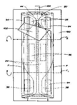
FIG. 6 shows the sanitary napkin 20 after it has been folded and placed on a
releasable wrapper (or "main wrapping sheet") 100 that will serve as an
individual
package for the sanitary napkin 20. The releasable wrapper 100 has an inside
surface, an outside surface. The inside surface of the releasable wrapper 100
is
CA 02271488 1999-OS-12
WO 98/20823 PCT/US97%20110
capable of releasably adhering the releasable wrapper 100 to the adhesive
fasteners)
on the sanitary napkin 20. This releasability can be achieved in a number of
ways.
Several preferred ways are described in the patents that disclose releasable
wrappers
which are incorporated by reference herein.
As shown in FIG. 6, the lobes 38 and side wrapping elements 24 of the
sanitary napkin 20 are preferably folded inward along longitudinal fold lines,
F, over
the topsheet 44. This exposes the pairs of adhesive patches 94 in the end
regions of
the sanitary napkin and the adhesive side wrapping element fasteners 96. The
sanitary napkin 20 is placed garment surface 20B down on the releasable
wrapper
100 so that the central pad fastener 94 is releasably attached to the inside
surface of
the releasable wrapper 100. The exposed pairs of adhesive patches 94 in each
end
region of the sanitary napkin and the side wrapping element fasteners 96 are
then
covered with a single sheet of strip of release paper (or "release element")
102 that
preferably extends substantially the entire length of the main body portion
22. The
strip of release paper 102 has an inside surface capable of releasably
adhering to the
adhesive fasteners) on the sanitary napkin 20. The sanitary napkin 20 and the
releasable wrapper 100 are then preferably folded about a pair of spaced apart
transverse axes F 1 and F2 to form an individual package for the sanitary
napkin 20.
The releasable wrapper 100 is preferably provided with a releasable adhesive
wrapper closure fastener, such as adhesive tape tab 104, for retaining the
folded
sanitary napkin and wrapper in their folded configuration.
FIGS. 7 and 8 show the folding of the sanitary napkin 20 and releasable
wrapper 100 to form an individual package for the sanitary napkin. FIG. 7
shows
that the second end region 34 of the sanitary napkin 20 is folded over the
central
region 36 of the sanitary napkin 20. The first end region 32 of the sanitary
napkin 20
is then folded on top of the second end region 34. FIG. 8 shows that the
adhesive
tape tab 104 is then used to releasably secure the sanitary napkin 20 in its
folded
configuration. In a particularly preferred embodiment, the longitudinal edges
l06 of
the releasable wrapper 100 extend beyond the side edges of the folded sanitary
napkin 20. The longitudinal edges 106 of the releasable wrapper 100 are
preferably
frangibly sealed together to close off the sides of the package. Suitable
methods for
frangibly sealing the longitudinal edges 106 of such a package are described
in U.S.
Patent 4,556,146 issued to Swanson, et al., U.S. Patent S,181,610 issued to
Quick,
and U. S. Patent 5,462,166 issued to Minton, et al.
CA 02271488 1999-OS-12
WO 98/20823 PCT/US97~20110
26
The folded configuration shown in FIGS. 6-8 provides the advantage that it
produces a relatively small and convenient package for a relatively large pad.
The
folded package preferably has overall dimensions of about 5.5 inches (about 14
cm)
measured in the longitudinal direction, about 5 inches (about 13 cm) in width,
and
less than or equal to about 1 inch (2.5 cm) in thickness.
The sanitary napkin 20 is removed for use by peeling open the tape tab 104
then unfolding the end regions of the sanitary napkin 20 in the reverse order
that they
were originally folded to package the sanitary napkin 20. This breaks the
frangible
seals along the longitudinal side edges 106 of the releasable wrapper 100 and
places
the sanitary napkin 20 and releasable wrapper 100 in the flat, laid out
configuration
shown in FIG. 6. The consumer can then peel away the releasable wrapper 100
from
the central body fastener 94. The consumer can thereafter place the sanitary
napkin
20 in the crotch region of her panties and can adjust the sanitary napkin
until it is in
the desired position. This can all be done while the strip of release paper
102 still
covers the fasteners on the lobes 38 of the sanitary napkin and on the side
wrapping
elements 24. This provides the advantage that the fasteners 94 and 96 on these
portions of the sanitary napkin 20 will not be able to fold over on themselves
and
stick to themselves or to the wrong portion of the wearer's panties. The
consumer
can then peel back the release strip 102 and unfold the lobes 3 8 and the side
wrapping elements 24. The consumer can then secure the lobes 3 8 to her
panties
and fold the side wrapping elements 24 around the edge of her panties and
attach the
side wrapping element fasteners 96 to the underside of her panties.
Figure 9 is a depiction of the sanitary napkin 20 in place in an undergarment
of
the type commonly worn by many women and well known as a panty 10. The
configuration of the sanitary napkin 20 in the panty shown in FIG. 9 is
presented
primarily for purposes of discussion, rather than to limit the possible
configurations
the sanitary napkin may take in use. It should be understood that the sanitary
napkin
20 described herein may also take other configurations in use. For example,
the side
wrapping _ elements of the sanitary napkin 20 can, if desired, take in-use
configurations similar to those of the flaps described in U.S. Patents
4,687,478 and
5,267,992 issued to Van Tilburg or U. S. Patent 5,354,400 issued to Lavash, et
al.
The in-use configuration may, however, differ in some respects since the span
of the
side wrapping elements 24 will typically be less than such flaps.
The panty 10 comprises a crotch portion 12, a front section 14, and a back
section 16: The crotch portion 12 joins the front and back sections and
comprises
CA 02271488 1999-OS-12
WO 98I20823 PCT/US97120110
27
two elasticized side edges 18. As shown in Figure 9, the center of main body
portion
22 is placed in the crotch portion 12 of the panty 10 with the backsheet in
contact
with the inner surface of crotch portion 12 of the panty and one end of main
body
portion 22 extending towards the front section 14 of the panty and the other
end
towards the back section 16. The central pad adhesive 94 maintains main body
portion 22 in position. The distal portions 76 of side wrapping elements 24
are
folded around the elasticized side edges 18 of the panty. The flap adhesive
portions
96 secure the side wrapping elements 24 to the underside of the panty.
FIGS. 10 and 11 show an alternative way of covering the adhesive fasteners
on the garment facing side of the sanitary napkin. As FIG. 10 shows, in this
embodiment, the side wrapping elements 24 are folded over the body-facing side
20A of the main body portion 22 and the adhesive fasteners 96 thereon are
covered
with a unitary release strip 110. As shown in FIG. 11, the adhesive fasteners
94 on
the garment-facing side 20B of the main body portion 22 are covered with
multiple
release papers such as release papers 112 and 114. Preferably, these multiple
release
papers 112 and 114 are oriented in an end-to-end relationship in the
longitudinal
direction. Each of the release papers 112 and 114 generally resembles the
shape of
half of an hourglass. The release papers 112 and 114 preferably have a portion
adjacent at least one edge, which is preferably an end edge, such as 112A)
that is
non-adhesive, that overlaps with a portion adjacent the end edge (such as
114A) of
the adjacent release paper. In the preferred embodiment shown, the non-
adhesive
end edge is preferably also folded back (such as along F3 and F4) to provide a
graspable tab 116 and 118 for the consumer to hold in order to more easily
remove
the release papers 112 and 114.
In other embodiments, the end edges of the release papers may abut, rather
than overlap. In still other (but, less preferred) embodiments, the end edges
may be
spaced slightly apart. Numerous other embodiments of multiple release paper
arrangements are also possible. For example, in other embodiments, the
multiple
release papers may be arranged in a side-by-side arrangement, rather than end
to end.
In these or other embodiments, more than two release papers can be used. In
addition, it is not necessary for the dividing line between the release papers
to by
symmetrically disposed relative to the sanitary napkin. For instance, if two
release
papers are used, one could cover more than half of the sanitary napkin and the
other
could cover less than half of the sanitary napkin. Further, the multiple
release papers
can also be provided with arrows, or some other suitable indicia, to indicate
to the
user where to peel open the release papers.
CA 02271488 1999-OS-12
WO 98I20823 PCTIUS97/20110
28
The multiple release paper embodiments described above are particularly
useful when the main body portion 22 of the sanitary napkin is extensible,
highly
flexible, or both. Such multiple release paper arrangements provide ease in
handling
these types of sanitary napkins and allow the wearer to place the same in her
panties
without portions of the adhesive fastener on the sanitary napkin folding over
and
inadvertently sticking to other portions of the sanitary napkin.
In the multiple piece release paper embodiments, or in any of the other
embodiments described herein, the release paper could be provided with
additional
stiffness to aid in handling extensible and/or highly flexible sanitary
napkins. This
release paper is preferably stiffer than release papers currently in use. More
specifically, the release paper preferably has a stiffness of greater than or
equal to
about 1.0 grams-cm measured according to the Association of Nonwoven Fabric
Industry test INDA IST 90. I-92, and/or a Taber Stiffness of greater than or
equal to
about 0.12 grams-cm measured according to TAPPI test T489 os-76. More
preferably, the release paper can have a stiffness of Beater than or equal to
1.1, 1.2,
1.3, . . ., etc. grams-cm under the INDA test and/or 0.13, 0.14, 0.15, . . .,
etc. under
the Taber Stiffness test. The rest of the numbers in the series are included
herein
even though they are not specifically listed. The release paper can have a
stiffness up
to, or exceeding that of the stiffness of the sanitary napkin measured without
a
release paper thereon. This will allow the sanitary napkin 20 to have
stiffness when
desired, such as to aid in handling the sanitary napkin, without altering the
properties
of the sanitary napkin when flexibility is desired, such as when the sanitary
napkin 20
is placed in the wearer's panties.
FIG. 12 shows another alternative way of covering the adhesive fasteners 94
on the garment facing side of the sanitary napkin. In the embodiment shown in
FIG.
12, the adhesive fasteners 94 are disposed in the configuration of a number of
spaced
apart circular regions of adhesive. (It should be understood, however, that
this
adhesive fastener configuration is merely for purposes of illustration, and
that this
adhesive cover embodiment, like the previous embodiments, is not limited to
use
with the particular adhesive fastener configuration shown in the drawings. )
The
adhesive fasteners 94 are covered with a release paper 120 that is perforated
so that
it can be separated into more than one piece for removal. More specifically,
the
embodiment shown in FIG. 12 comprises an hourglass-shaped release strip 120
that
has a perforated line 122 in a dog bone shape in the center. The perforated
line 122
allows the user to separately remove the dog bone-shaped piece 124 and the
remainder of the release paper 120. The release paper 120 and the perforation
line
CA 02271488 1999-OS-12
WO 98/20823 PCT/US97/x0110
29
122, however, can be in any desired configuration that allows the release
paper 120
to be separated into more than one piece for removal. The embodiment shown in
FIG. 1 Z provides the advantage that it allows the wearer to remove selected
portions
of the release strip so that certain portions of the adhesive fastener 94 will
be
exposed to control the amount and location of the adherence of the sanitary
napkin
20 to their undergarment.
Numerous other alternative embodiments of the absorbent article and
releasable cover arrangements described herein are possible. For example, any
of the
releasable cover arrangements described herein can be applied to sanitary
napkins,
pantiliners, and adult incontinence pads, or other types of absorbent
articles,
regardless of the type and configuration of the absorbent article, or the
fastener
thereon, as long as the releasable cover is compatible with the absorbent
article and
fastener. Suitable absorbent articles in the form of pantiliners that could be
provided
with the fasteners and releasable cover arrangements of the present invention
are
disclosed in U.S. Patent 4,738,676 entitled "Pantiliner" issued to Osborn on
April 19,
1988. Suitable absorbent articles, at least some of which are in the form of
adult
incontinence products that could be provided with the features of the present
invention, are described in U.S. Patents 5,300,054 issued to Feist, et al. on
April 5,
1994, and 5,304,161 issued to Noei, et al. on April 19, 1994. In addition, if
the
fasteners comprise a type of fastener other than the pressure sensitive
adhesive, for
instance, a mechanical fastener, such as a hook material, the fastener may be
covered
by a material that (engages and) releases from the same, such as a loop
material, or a
nonwoven material, etc. rather than covering the fasteners with conventional
types of
silicone-coated release papers.
The disclosures of all patents, patent applications (and any patents which
issue
thereon, as well as any corresponding published foreign patent applications),
and
publications mentioned throughout this description are hereby incorporated by
reference herein. It is expressly not admitted, however, that any of the
documents
incorporated by reference herein teach or disclose the present invention.
While particular embodiments of the 'present invention have been illustrated
and described, it would be obvious to those skilled in the art that various
other
changes and modifications can be made without departing from the spirit and
scope
of the invention.