Language selection

Search

Patent 2271584 Summary

Third-party information liability

Some of the information on this Web page has been provided by external sources. The Government of Canada is not responsible for the accuracy, reliability or currency of the information supplied by external sources. Users wishing to rely upon this information should consult directly with the source of the information. Content provided by external sources is not subject to official languages, privacy and accessibility requirements.

Claims and Abstract availability

Any discrepancies in the text and image of the Claims and Abstract are due to differing posting times. Text of the Claims and Abstract are posted:

  • At the time the application is open to public inspection;
  • At the time of issue of the patent (grant).
(12) Patent: (11) CA 2271584
(54) English Title: MULTI TASK GRINDING WHEEL MACHINE
(54) French Title: MEULE A DOUBLE FONCTION
Status: Expired and beyond the Period of Reversal
Bibliographic Data
(51) International Patent Classification (IPC):
  • B24B 19/00 (2006.01)
  • B21B 28/02 (2006.01)
  • B24B 5/37 (2006.01)
  • B24B 19/02 (2006.01)
  • B24B 27/00 (2006.01)
  • B24B 49/02 (2006.01)
(72) Inventors :
  • FABRIS, MARIO (Canada)
(73) Owners :
  • MARIO FABRIS
(71) Applicants :
  • MARIO FABRIS (Canada)
(74) Agent: EDWARD H. OLDHAMOLDHAM, EDWARD H.
(74) Associate agent:
(45) Issued: 2003-09-09
(22) Filed Date: 1999-05-12
(41) Open to Public Inspection: 2000-11-12
Examination requested: 1999-05-12
Availability of licence: N/A
Dedicated to the Public: N/A
(25) Language of filing: English

Patent Cooperation Treaty (PCT): No

(30) Application Priority Data: None

Abstracts

English Abstract

This application describes a grinder for grinding a workpiece situated so as to be accessible to two separate grinding wheels simultaneously. A grinding operation may be carried out on a workpiece to simultaneously grind different profiles on the workpiece without removal from the workpiece spindle.


French Abstract

Cette application décrit une meule destinée à moudre une pièce placée de manière à être accessible simultanément à deux meules distinctes. Une opération de meulage peut être effectuée sur une pièce pour moudre simultanément différents profils sur la pièce sans nécessiter le retrait de l'axe de la pièce.

Claims

Note: Claims are shown in the official language in which they were submitted.

Claims
I claim:
1. A grinding machine having a specifically defined X and Y axes in an x, y
coordinate drive system for
precisely grinding a selected area of a roll to a predetermined shape of
specific dimensions comprising:
means to mount and rotate said roll about a fixed reference axis in said x, y
coordinate system of said
machine,
a first grinding means moving in said x, y axis for rotatably engaging the
peripheral surface at a first side
of said rotating roll to produce a cylindrical surface on the periphery
thereof by grinding,
and;
a second grinding means moving in said x, y axes for simultaneously rotatably
engaging said periphery
of said roll on a side opposite said first side to simultaneously grind a
groove in said cylindrical surface,
said first and second grinding means being mounted in juxtaposition with said
means to mount and
rotate said roll on said machine.
2. A grinding machine as claimed in claim 1 wherein the axes of rotation of
said roll and said grinding
means are substantially parallel.
3. A grinding machine as claimed in claim 2 wherein gauging means monitors and
measures the
peripheral surface of said roll to produce output signals corresponding to
said peripheral surface
dimensions.
4. A grinding machine as claimed in claim 3 wherein said output signals are
fed into a control device to
control the movement of said first and second grinding means in said x, y
axes.
5. A grinding machine for mounting and grinding a workpiece thereon
comprising:
a base having at least three powered spindle devices mounted thereon such that
the three spindles are
mounted in a common plane,
a first spindle device having a chucking device secured to one end thereof for
mounting a workpiece
thereon, said first spindle device being rigidly mounted on said base,
a second spindle device moving in said plane along x and y axes in an x,y
coordinate system, and being
mounted on said base on one side of said first spindle device, said second
spindle device having a first
grinding wheel secured to one end of said spindle device,
a third spindle device moving in said plane along x and y axes in said x,y
coordinate to system, and being
mounted on said base on the opposite side of said first spindle device from
said second spindle device,
said third spindle device having a second grinding wheel secured to one end of
said third spindle device,
said second and third spindle devices being controllably movable in said plane
so as to controllably
engage their respective grinding wheels with a common grinding area of said
workpiece for

simultaneously grinding said area of said workpiece as it rotates, said first,
second, and third spindle
devices being located in a side by side relationship on said base.
6. A grinding machine as claimed in claim 5 wherein said first grinding wheel
mounted on said second
spindle device is used for grinding a circular groove in said workpiece,
and said second grinding wheel on said third spindle device is capable of
producing a cylindrical surface
on said workpiece.
7. A grinding machine for grinding the peripheral surface of an annular roll
to a predetermined shape
and finish comprising:
a motorized workpiece spinning device fixedly mounted in said machine for
chucking and rotating said
roll about a fixed axis of rotation in a fixed plane,
a first motorized grinding device having a first grinding wheel rotating about
a first spin axis, having a
first motion control means to control the motion of said first motorized
grinding device about two
orthogonal co-ordinate axes,
a second motorized grinding device having a second grinding wheel rotating
about a second spin axis,
and having a second motion control means to control the motion of said second
motorized grinding
device about two orthogonal co-ordinate axes,
said first and second grinding devices being mounted on said machine in side
by side relationship on
opposing sides of said workpiece spinning device for suitable simultaneous
engagement with the same
area of said workpiece so that the planes in which said roll and said grinding
devices rotate are
maintained in a parallel relationship regardless of the motion of said
grinding devices,
and access to said roll from a side of said fixed plane remote from said
motorized workpiece spinning
device is unobstructed.
8. A grinding machine as claimed in claim 7 wherein said first grinding device
is equipped with a
cylindrical grinding wheel,
and said second grinding device is equipped with a grinding wheel having the
general shape of a disc.
9. A grinding machine as claimed in claim 8 wherein one of the control axes is
parallel to the spin axis
of each grinding device.
10. A numerically controlled grinding machine for the production of precisely
shaped rolling rolls
comprising:
a rigid base having a housing fixedly mounted thereon,
said housing having a powered spindle mounted for rotation therein,
said spindle having means for securing a roll in a chucking device at one end
thereof for rotating said
roll so that said roll overhangs,
a first powered grinding device having a grinding wheel mounted thereon,

said first grinding device being mounted on said base on one side of said
housing, and
having an x and y co-ordinate drive means to move said first grinding device
about "x" and "y" axes in a
plane parallel to said base for suitable controlled engagement of said
grinding wheel with a preselected
area of said rotating roll,
a second powered grinding device having a grinding wheel mounted thereon,
said second device being mounted on said base on the opposite side of said
housing from said first
powered grinding device,
said second powered grinding device mounted on said base having an "x" and "y"
co-ordinate drive
means to move said second powered grinding device about "x" and "y" axes in a
plane parallel to said
base, for suitable controlled simultaneous engagement with said preselected
area on the opposite side of
said rotating roll from said first grinding device,
said first and second powered grinding devices being mounted in juxtaposition
with said powered
spindle so that access to said roll is unobstructed for mounting and
dismounting of said roll on said
spindle.
11. A grinding machine as claimed in claim 10 wherein said "x" and "y" axes of
said first and second
grinding devices coincide and wherein said first grinding device functions to
grind a cylindrical surface
on said rotating roll,
and said second grinding wheel functions to produce a groove in said
cylindrical surface of said roll.
12. A grinding machine as claimed in claim 11 wherein gauging means is mounted
to monitor the size
and surface profile of said rotating roll,
and produce a set of output signals corresponding to said size and surface
profile of said rotating roll,
whereby said "x" and "y" co-ordinate drive means are controlled in accordance
with said signals.
13. A grinding machine as claimed in claim 12 wherein the second powered
grinding device is equipped
with a grinding wheel having the general shape of a disc.
14. A method of grinding the surface of a workpiece comprising:
mounting the workpiece on a suitable rotatable mandrel, rotating said
workpiece and mandrel at a pre-
selected rotational speed,
bringing a first grinding means into contact with a preselected area of the
surface of said rotating
workpiece, said first grinding means moving along x and y axes in an x,y
coordinate system, and
simultaneously brining a second grinding means into contact with the same area
of surface of said
rotating workpiece from a direction radially opposite said first grinding
means, said second grinding
means moving along x and y axes in said x,y coordinate system, and
simultaneously grinding the surface
of said rotating workpiece with both grinding means to a predetermined surface
profile, retracting both
grinding means from the surface of said workpiece, stopping the rotation of
said workpiece and,
removing workpiece from said mandrel.
15. A method of grinding the surface of a workpiece as claimed in claim 14
wherein said mandrel and
said first and second grinding means are separately driven by first, second
and third driving means and

wherein all said driving means are located adjacent one another.
16. A method as claimed in claim 15 wherein said first grinding means produces
a cylindrical grinding
surface on said workpiece, and said second grinding means produces a groove in
said surface.
17. A method as claimed in claim 16 wherein free access is gained to said
workpiece for demounting
said workpiece from said mandrel when said first and second grinding means are
retracted from said
surface.
18. A method as claimed in claim 17 wherein said driving means are electric
motors.

Description

Note: Descriptions are shown in the official language in which they were submitted.


CA 02271584 1999-OS-12
- 1 - EHO-97118
MULTI-TASK GRINDING WI~EL MACHINE
This invention relates to a production type machine which
may be used to produce very accurate cylindrical profiles and
finishes on circular workpieces which are rotating whilst being
shaped and ground. The invention will be of the form of a grinding
machine which utilizes three rotating spindles, a first spindle on
which the circular workpiece (a roll for instance) is mounted for
rotation about the workpiece spindl'!e axis, a second spindle having a
grinding wheel installed thereon for performing a cylindrical
grinding operation on the workpiece, and a third spindle having a
different shaped grinding wheel insaalled thereon for performing a
different type of grinding operation. on the workpiece, say, a profile
forming operation which is done simultaneously with the grinding
operation being performed on the workpiece by the first grinding
wheel. By the use of modern gauging and measuring techniques, the
control and feed of both grinding wheels may be computer
controlled to permit simultaneous grinding by the two grinding
wheels and produce a work producl: which will be within specified
dimensions and tolerances.

CA 02271584 1999-OS-12
- 2 - EHO-97118
BACKGROUND OF THl? INVENTION
For some industrial applications, the success of the manufacture of
a product depends on the accuracy of the dimensions of a matched pair of
rotating roll between which a product must pass during manufacture.
In particular, in the steel industry, for instance, many of the
manufacturing operations involve passing a work product between a pair
of work rolls having a specially matched, profile of a particular shape to
form the work product as it passes between the matched pair of work
rolls. In a process for producing steel wire from billet type stock, the
work product must be passed through a large number of reducing mill
stands to produce the final product. Each mill stand comprises at least a
pair of matched work rolls through which the work product must pass.
Because of the hostile nature of the material passing between the work
rolls, the surfaces of the work rolls will become worn (past a utilization
standard) so that the work rolls must be reground and reprofiled. This
invention finds application in the regrinding and profiling of worn work
rolls and may also find suitable application in the manufacture of new
work rolls. The invention may be advantageously applied to grinding
workpieces (other than work rolls) of a. of a configuration where multiple
operations must be performed on the same workpiece.
The problem of accurately grinding matched sets of work rolls for
various industrial manufacturing operations has been dealt with in the
workplace by tool and die makers for some considerable time. The
durability of the rolls in a manufacturing operation has improved as the

CA 02271584 2002-11-29
EHO 97118
-3-
technology of processes and material has evolved. Rolls that once were
manufactured from steel were replaced with high performance tool steel
(which is machinable) only to be replaced with carbide rolls. These rolls
contain about 70 to 90% tungsten carbide and are extremely difficult to
s manufacture by machining, thus in most instances manufacture of
tungsten carbide rolls is accomplished by grinding with diamond grinding
wheels. Because of the multitude of shapes and sizes of rolls used in a
steel manufacturing operation, the regrinding operation may require many
diamond wheels, each having a peculiar contour for the production of a
io specified profile in a particular pair (matched) or rolls in the production
facility.
SUMMARY OF THE INVENTION
This invention is directed to a grinding machine which is effective
i s in producing a prescribed profile and a prescribed outer diameter (OD)
for a specified roll in a very short time. The production of such a roll is
made possible by the provision of three separate rotating spindles which
in this instance, all have parallel axes of rotation but in some
circumstances, it may be advantageous to have one or more of the
ao grinding axis non-parallel to the work spindle axis.
A rotating spindle having a chucking device of the nature of the
device described in applicant's U.S. Patent No. 5, 556,114 is mounted
between a pair of rotatable spindles each carrying a separate and distinct
as type of grinding wheel.

CA 02271584 1999-OS-12
- 4 - EHO-97118
The axis of both grinding wheel spindles are controllably movable
in both x and y axis to allow each grinding wheel to separately and
independently move to produce its desired operation.
A finished roll is produced by ;simultaneous grinding while
gauging is simultaneously carried out to control the grinding operations
without having to remove the roll from the original set up.
It will be seen that the time required to produce a superior product
is drastically reduced over prior art procedures. The capital costs of the
inventory of profiled grinding wheels is avoided.
The grinding machine of this invention is by its nature very rugged
and the possibility of "chatter" is reduced to a minimum, thus excellent
surface finishes are obtained in a very short time.
This machine does not require a tailstock to stabilize the
workpiece, thus the "load" and "unloa.d" operations of the workpiece is
unencumbered by the presence of a tailstock or other grinder parts
extending outwardly along the spindlE: axis which would usually be
present for the mounting of a tailstock: thereon. This feature will increase
the chances of applying automatic shop procedures for the mounting and
dismounting of the workpieces on the chucking device on the workpiece
spindle.
This configuration too, is conducive to the production of a practical
ergometric method of loading and unloading rolls in the grinding
machine, because the operator may stand and face the roll chuck instead

CA 02271584 2002-11-29
EHO 97118
- 5-
of having to lean over the ledge of the grinding machine to insert a heavy
roll onto a chuck in the grinding machine.
BRIEF DESCRIPTION OF DRAWINGS
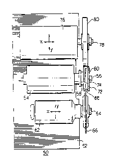
s Figure 1 is a plan view of the grinding machine of this invention;
Figure 2 is an elevation view of the grinding machine of this
invention;
Figure 3 is a block diagram showing the control circuit for the
movement of the grinding machines of Figure 1;
io
Referring now to Figure l, a grinding machine 50 embodying this
invention is illustrated. Machine 50 comprises a base 52 on which are
mounted three separate motors each driving separate spindles. In the
center of the base 52 is motor 54 which is rigidly attached to base 52.
is Motor 54 houses a spindle 56 on which is mounted a chucking device 58.
Chucking device 58 is preferably the chucking device of U.s. Patent No.
5,556,114 on which workpiece 60 is clamped. This chucking device
which does not require a tailstock, nevertheless is able to provide a rigid
mounting for workpiece 60.
Also mounted on base 52 is a grinding motor 62 which has a
spindle 64 on which grinding wheel 66 is mounted. Grinding 62 is
mounted on drive assembly 70 (Figure 2) which allows the grinding 62 to
be moved in the x and y axial direction by a CNC system. By this means,
2s the specially shaped wheel 66 is made to execute a motion so as to

CA 02271584 1999-OS-12
- 6 - EHO-97118
produce the groove 68 in workpiece 60. This motion is preferably
produced by ball screw drives which drive the grinder in a very precise
fashion in both the x and y directions. The particular drives chosen are
rugged and can produce very accurate motion of the grinding devices
with little or no deadband effects. These devices are commonly used for
such accurate types of drives and the accuracy and long life is achieved
by recirculating balls in a helix formed between a "nut" and "threaded
shaft".
At the same time as groove 68 is being formed, a gauging
mechanism continuously measures and monitors the depth and contour of
groove 68 by a MARPOSSTM gauging; system. This system provides a
feedback signal to the CNC mechanism to control the "x" and "y" motion
of the grinding machine 62. A printout by the MARPOSSTM system is
produced to detail the groove profile.
As the profile groove 68 is being produced by wheel 66 and
monitored by the MARPOSSTM gauging system, the cylindrical surfaces
72 and 74 of workpiece 60 are being ground to specification by grinding
machine 76.
Grinding machine 76 comprises a motor housing a spindle 78 on
which grinding wheel 80 is mounted. Grinding machine 76 is also
movably controlled in both "x" and "y" axis in a manner similar to
grinding machine 62. Machine 76 must be accurately controlled in the y
direction and thus utilizes a ball screw device type drive for the execution
of "y" motion. The motion executed by grinder 76 in the "x" direction

CA 02271584 1999-OS-12
7 - EHO-97118
i.e. along the axis of spindle 78, for this application is merely an
oscillatory motion and for economic purposes and in this instance, is
controlled by using a hydraulic driving and controlling means in the "x"
direction. (If the grinding operation performed by grinding machine 76 is
such that precise control is required in the "x" axis, the hydraulic drive
will be replaced by a ball screw drive;).
At the same time, the surface abrasion is being constantly
measured and continuously monitored by a MARPOSSTM gauging system
which produces a printout of the details of the surfaces 72 and 74.
The control circuit for the drivers for the grinders of machine 50 is
shown in Figure 3.
MARPOSSTM gauge equipment is shown in block 84 for
monitoring the surface of roll 60. Signals are sent via line 86 to the
Computerized Numerical Control Device 88 where the signal data from
block 84 is stored and processed.
Reference data is fed by the operator into line 90 where it is
processed and compared with the data from block 84. Drive signals for
the "x" and "y" co-ordinate drives 70 and 82 are produced and sent to the
drives by lines 92 and 94 to cause the drives to execute the precise
motion of the respective grinding machines dictated by the CNC device.
Grinding machine 50 is therefore capable of producing a re-
manufactured roll or workpiece 60 to very tight specifications in a very
short time. Because roll 60 is mounted on chucking device 58 only once,

CA 02271584 1999-OS-12
- 8 - EHO-97118
the problems associated with mounting, dismounting and remounting the
work in one or more grinding machines is eliminated.
Because the two grinding opf;rations are carried on simultaneously,
the two ground surfaces i.e. the cylindrical surface and the groove surface
must be concentric.
Thus, the quality of the re-manufactured workpiece is improved
whilst the throughput is increased. Operator fatigue is somewhat
lessened by employment of this apparatus and method of grinding.
Workpieces such as 60 are usually produced as identical matched
pairs for production of roll formed products in the steel industry for
instance, thus the ability to repeat the dimensions of roll 60 for its mate is
mandatory, and will be readily accomplished by the apparatus of this
invention.
Operator training for the production of new or re-manufactured
devices such as roll 60 is minimizeal because of the single mounting
requirement for the roll in machine .50. The machine 50 may be pre-
programmed to produce the desired profile and OD for various size
workpieces.
The MARPOSSTM gauging system provides excellent means to
control the overall grinding system.

CA 02271584 1999-OS-12
- 9 - EHO-97118
The grinding operation must be carried on in the presence of a
cooling fluid which maintains the temperature of the workpiece as
constant as possible.
The relative sizes and speeds of the grinders and workpiece drive
may typically be as follows:
Workpiece OD 6 to 14 inches
Drive 3HP 24 - 70 RPM
PROFILE GRINDER - 16 inch wheel
SHP Speed 1450 RPM
CYLINDRICAL, GRINDER 24 inch wheel
10 HP 900 RPM
This invention has been described and illustrated with respect to
the production of rolls used in the steel industry. While this invention
has excellent application for the purposes described previously herein,
the advantages of this invention may be advantageously employed
whenever more than one surface preparation operation is required for a
rotating workpiece.
This application has illustrated motorized grinding machines for
grinding workpieces. Those skilled in the art will realize that for certain
grinding operations, the rotating spindles may be driven by belts, gears or
shafts for a variety of reasons.

CA 02271584 1999-OS-12
- 10 - EHO-97118
It is not absolutely necessary that the axes of the three spindles be
co-planar, but best results will be obtained if the three spindles are kept
substantially co-planar.
Although variations in the apparatus are possible, applicant wishes
to limit the ambit of protection to the following claims.

Representative Drawing
A single figure which represents the drawing illustrating the invention.
Administrative Status

2024-08-01:As part of the Next Generation Patents (NGP) transition, the Canadian Patents Database (CPD) now contains a more detailed Event History, which replicates the Event Log of our new back-office solution.

Please note that "Inactive:" events refers to events no longer in use in our new back-office solution.

For a clearer understanding of the status of the application/patent presented on this page, the site Disclaimer , as well as the definitions for Patent , Event History , Maintenance Fee  and Payment History  should be consulted.

Event History

Description Date
Time Limit for Reversal Expired 2018-05-14
Letter Sent 2017-05-12
Inactive: Office letter 2012-06-19
Inactive: Late MF processed 2012-06-05
Inactive: Payment - Insufficient fee 2012-05-24
Letter Sent 2012-05-14
Small Entity Declaration Determined Compliant 2008-04-17
Inactive: IPC from MCD 2006-03-12
Grant by Issuance 2003-09-09
Inactive: Cover page published 2003-09-08
Pre-grant 2003-06-10
Inactive: Final fee received 2003-06-10
Notice of Allowance is Issued 2003-06-04
Letter Sent 2003-06-04
Notice of Allowance is Issued 2003-06-04
Inactive: Approved for allowance (AFA) 2003-05-23
Amendment Received - Voluntary Amendment 2003-04-14
Inactive: S.30(2) Rules - Examiner requisition 2003-04-01
Inactive: Delete abandonment 2003-02-18
Inactive: Adhoc Request Documented 2003-02-18
Inactive: Abandoned - No reply to s.30(2) Rules requisition 2002-12-02
Amendment Received - Voluntary Amendment 2002-11-29
Inactive: S.30(2) Rules - Examiner requisition 2002-05-31
Inactive: Office letter 2000-12-19
Inactive: Correspondence - Prosecution 2000-12-18
Inactive: Adhoc Request Documented 2000-11-28
Request for Examination Received 2000-11-28
Application Published (Open to Public Inspection) 2000-11-12
Inactive: Cover page published 2000-11-12
Inactive: First IPC assigned 1999-06-30
Letter Sent 1999-06-22
Letter Sent 1999-06-17
Inactive: Filing certificate - No RFE (English) 1999-06-16
Filing Requirements Determined Compliant 1999-06-16
Application Received - Regular National 1999-06-10
Amendment Received - Voluntary Amendment 1999-05-12
Request for Examination Requirements Determined Compliant 1999-05-12
All Requirements for Examination Determined Compliant 1999-05-12
Request for Examination Received 1999-05-12

Abandonment History

There is no abandonment history.

Maintenance Fee

The last payment was received on 2003-04-15

Note : If the full payment has not been received on or before the date indicated, a further fee may be required which may be one of the following

  • the reinstatement fee;
  • the late payment fee; or
  • additional fee to reverse deemed expiry.

Please refer to the CIPO Patent Fees web page to see all current fee amounts.

Fee History

Fee Type Anniversary Year Due Date Paid Date
Application fee - small 1999-05-12
Request for examination - small 1999-05-12
MF (application, 2nd anniv.) - small 02 2001-05-14 2001-03-02
MF (application, 3rd anniv.) - small 03 2002-05-13 2002-04-16
MF (application, 4th anniv.) - small 04 2003-05-12 2003-04-15
Final fee - small 2003-06-10
MF (patent, 5th anniv.) - small 2004-05-12 2004-04-15
MF (patent, 6th anniv.) - small 2005-05-12 2005-04-18
MF (patent, 7th anniv.) - small 2006-05-12 2006-04-12
MF (patent, 8th anniv.) - small 2007-05-14 2007-04-19
MF (patent, 9th anniv.) - small 2008-05-12 2008-04-17
MF (patent, 10th anniv.) - small 2009-05-12 2009-04-15
MF (patent, 11th anniv.) - small 2010-05-12 2010-03-15
MF (patent, 12th anniv.) - small 2011-05-12 2011-04-15
MF (patent, 13th anniv.) - small 2012-05-14 2012-05-16
Reversal of deemed expiry 2012-05-14 2012-05-16
2012-06-05
MF (patent, 14th anniv.) - small 2013-05-13 2013-03-18
MF (patent, 15th anniv.) - small 2014-05-12 2014-04-09
MF (patent, 16th anniv.) - standard 2015-05-12 2015-04-22
MF (patent, 17th anniv.) - standard 2016-05-12 2016-04-20
Owners on Record

Note: Records showing the ownership history in alphabetical order.

Current Owners on Record
MARIO FABRIS
Past Owners on Record
None
Past Owners that do not appear in the "Owners on Record" listing will appear in other documentation within the application.
Documents

To view selected files, please enter reCAPTCHA code :


To view images, click a link in the Document Description column. To download the documents, select one or more checkboxes in the first column and then click the "Download Selected in PDF format (Zip Archive)" or the "Download Selected as Single PDF" button.

List of published and non-published patent-specific documents on the CPD .

If you have any difficulty accessing content, you can call the Client Service Centre at 1-866-997-1936 or send them an e-mail at CIPO Client Service Centre.


Document
Description 
Date
(yyyy-mm-dd) 
Number of pages   Size of Image (KB) 
Drawings 1999-05-12 2 45
Representative drawing 2000-11-02 1 10
Description 2002-11-29 10 368
Claims 2002-11-29 4 225
Abstract 2003-04-14 1 11
Representative drawing 2003-08-07 1 9
Cover Page 2003-08-07 1 30
Description 1999-05-12 10 366
Abstract 1999-05-12 1 9
Claims 1999-05-12 6 240
Cover Page 2000-11-02 1 24
Acknowledgement of Request for Examination 1999-06-17 1 179
Filing Certificate (English) 1999-06-16 1 165
Reminder of maintenance fee due 2001-01-15 1 112
Commissioner's Notice - Application Found Allowable 2003-06-04 1 160
Notice of Insufficient fee payment (English) 2012-05-24 1 90
Maintenance Fee Notice 2012-05-24 1 172
Late Payment Acknowledgement 2012-06-19 1 165
Notice: Maintenance Fee Reminder 2016-02-15 1 119
Notice: Maintenance Fee Reminder 2017-02-14 1 120
Maintenance Fee Notice 2017-06-23 1 178
Maintenance Fee Notice 2017-06-23 1 179
Second Notice: Maintenance Fee Reminder 2017-11-15 1 130
Notice: Maintenance Fee Reminder 2018-02-13 1 128
Correspondence 1999-06-17 1 17
Correspondence 2000-12-19 1 6
Correspondence 2003-02-18 1 14
Correspondence 2003-06-10 1 30
Fees 2007-04-19 1 34
Correspondence 2008-04-17 1 45
Fees 2008-04-17 1 33
Fees 2009-04-15 1 38
Correspondence 2012-06-19 1 21
Fees 2012-06-05 1 30