Note: Descriptions are shown in the official language in which they were submitted.
CA 02271663 1999-OS-11
WO 98/21524 PCT/US97/15855
-1- -
AN IMPROVED PULVERIZED COAL BURNER
BACKGROUND OF THE INVENTIOrI'
This invention was made with government support under
Contract No. DE-AC22-92PC92160 awarded by the Department of
Energy. The government has certain rights in this invention.
1. FIELD OF THE INVENTI~
The present invention relates in general to fuel burners,
and in particular to an improved pulverized coal fuel burner
which limits nitrogen oxides (NOx) generation.
2. DESCRIPTION OF THE RELATED ART
Oxides of nitrogen (NOX) form in a flame such as a
pulverized coal flame when nitrogen bearing compounds are
released from the fuel. during pyrolysis. These compounds
combine with available oxygen to form NO and NO2, for-example
as shown in Fig. 1. Fig. 1 depi.cts~ typical NOX reaction
mechanisms. NOX can also be formed when high temperatures
(greater than 2700°F) are sustained in a flame region where
nitrogen and oxygen are present. ~;Tnder this condition, the
molecular nitrogen dissociates and recombines with oxygen
forming thermal NOX.
It is known that lower NOx emissions can be obtained from
pulverized coal flames by ~~staging~~ or delaying the mixing of
some of the combustion air with a :Fuel so that the released
nitrogen volatiles combine to form molecular nitrogen instead
of NOX. In the reducing atmosphere produced by staging,
molecules of NOX that do form can al:ao be more readily reduced
back to molecular nitrogen. This process of staging may be
completed externally to the burner by removing some of the
combustion air from the burner and introducing it at another
CA 02271663 1999-05-11
WO-98/21524 PCT/US97/15855
-2-
location in the furnace.
There exists aerodynamically air-staged burners
commercially available that operate on the principle of
internal staging where a low NOX flame is produced by
controlling the combustion air at the burner itself rather
than physically separating the locations of fuel and air
addition. The internal staging is accomplished by
aerodynamically distributing the combustion air across
multiple air zones. The internal staging is enhanced by the
addition of a swirl velocity to the combustion air and the use
of various burner hardware configurations to redirect the
combustion air streams. Burnout of the fuel is completed away
from the primary combustion zone as the redirected combustion
air mixes into the flame downstream. The Babcock & 4Vilcox
Company has developed, tested, and produced a series of
pulverized coal burners which reduce NOx emissions through the
use of multiple air zones. One example is shown in Fig. 2 and
offered commercially under the registered name DRB-XCL°
burner. This aerodynamically staged burner has been shown to
be successful at significantly reducing NOX levels from
standard high swirl burners which rapidly mix the fuel and air
near the burner exit. However, the longer flames produced by
this low-NOX burner design may exhibit lower combustion
efficiency through increased carbon monoxide (CO) emissions
and high levels of unburned carbon. In general, the measured
levels of exit NOX and combustion efficiency have been shown
through previous testing to be inversely related.
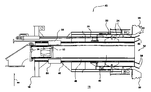
Referring to Fig. 2, there is shown a coal-fired DRB-XCL~
burner similar to the burner described in U.S. Patent No.
4,836,772 to LaRue. The burner (10) includes a conical
diffuser (12) and deflector (34) situated within the central
CA 02271663 1999-05-11
WO-98/21524 PCT/US97/15855
-3-
conduit of the burner (10) which is supplied with pulverized
coal and air by way of a fuel and primary air (transport air)
inlet (14). A windbox (16) is defined between the inner and
outer walls (18), (20) respectively. The windbox (16)
contains the burner conduit which is concentrically surrounded
by walls which contain an outer array of fixed spin vanes (22)
and adjustable vanes 1;24). An a_Lr separator plate (26),
concentrically around the burner nozzle, helps channel
secondary air supplied at (28). The burner (10) is provided
with a flame stabilizer (30) and a slide damper (32) for
controlling the amount of secondary air (28).
U.S. Patent No. 4,380,202 to LaRue et al. is also
relevant to a burner having a conica_L diffuser and some of the
other elements in Fig. 2. Impellers are routinely installed
on coal nozzles to reduce flame length at the expense of
emissions. Impellers and similar devices, such as swirlers
only change the fuel stream flow patterns. These approaches
can enhance fuel and air' mixing which increases NOx emissions.
U.S. Patent No. 4,479,442 to Itse et al. discloses a
venturi nozzle for pulverized coal including a divergent flow
separator and multiple swirl vanes.
There still exists a need for a.n advanced low-NOX burner
which obtains even lower NOX emi:~sions yet as a minimum
provides comparable unburned combustibles and carbon monoxide
(CO) emissions. Preferably, such a burner would deliver a
combined stream of pulverized coal and air with additional
streams of combustion air alone to control the combustion
characteristics of the pulverized coal flame. The burner
design would provide a stable, strong flame with both low
pollutant emissions and high combustion efficiency. This type
of burner configuration is preferable to allow the burner to
CA 02271663 1999-05-11
WO 98/21524 PCT/US97/15855
-4-
be installed in existing boilers or furnaces.
SZTi~KARY OF THE INVENTION
The present invention is directed to solving the
aforementioned problems with the prior art burners as well as
others by providing a burner which can achieve low NOx
emissions yet maintain high combustion efficiency. As used
herein, high combustion efficiency refers to the minimization
of the levels of unburned carbon and carbon monoxide leaving
the furnace. The present invention surpasses previous NOX
reduction limits by effectively combining aerodynamic
distribution of the combustion air to limit NOX generation
with unique burner features that provide a stable flame and
acceptable combustion efficiency. These features interact to
produce an efficient low NOX burner as described herein. The
present invention separates the primary and secondary streams
near the burner while employing a range of secondary air
velocities, to promote higher turbulence levels and improve
downstream mixing. Air distribution cones in combination with
__ 20 the transition zone permit redirection of secondary air
without dissipating swirl imparted to the secondary air by the
vanes. This further improves flame stability and downstream
mixing. Secondary air is separated physically and
aerodynamically from the core fuel zone near the burner by the
transition zone, thereby preventing direct fuel entrainment.
The use of secondary swirl and air distribution cones locally
redirects the air away from the flame core while still
permitting mixing downstream.
Accordingly, one object of the present invention is to
provide an advanced low NOX burner which diverts combustion
air away from the primary combustion region near the burner
CA 02271663 1999-OS-11
W O 98/21524 PCT/US9'7/15855
-5-
exit reducing the local stoichiometry during coal
devolatilization, and thus reducing initial NOX formation.
Another object of the present invention is to provide an
advanced low NOX burner which prov~_des a stable flame with
both low pollutant emis:~ions and high combustion efficiency.
Still a further object of the present invention is to
provide a burner which is simple in design, rugged in
construction and economical to manufacture.
The various features of novelty which characterize the
present invention are pointed out with particularity in the
claims annexed to and forming a part of this disclosure. For
a better understanding of the i:zvention, its operating
advantages and specific objects attained by its uses,
reference is made to the accompanyinc drawings and descriptive
matter in which the preferred embodiment of the invention is
illustrated.
BRIEF DESCRIPTION OF THE DRAWINGS
In the drawings:
Fig. 1 . is a graph illustrating NC>x reaction mechanisms;
Fig. 2 is a schematic sectional view of a known DRB-XCL~
burner which is improved ~>y the present invention;
Fig. 3 is a schematic sectional view of the present
invention;
Fig. 4 is a schematic' sectional view of a burner according
to the present invention showing the burner flame
characteristics; and
Fig. 5 is a schematic sectionau view of an alternate
embodiment according to the present invention.
CA 02271663 1999-OS-11
WO-98/21524 PCT/US97/15855
-6-
DESCRIPTION OF THE PREFERRED EMBODIMENT
Referring to the drawings where like numerals designate
like or similar features throughout the several views and
first to Fig. 3, there is shown a schematic sectional view of
the burner generally depicted (40) in accordance with the
present invention. Burner (40) which is also referred to as
the DRB-4ZT"' burner comprises a series of zones created by
concentrically surrounding walls in the burner conduit which
deliver a fuel such as pulverized coal with a limited stream
of transport air (primary air), and additional combustion air
(secondary air) pro-vided from the burner windbox (16). The
central zone (42) of the burner (40) is a circular cross-
section primary zone, or fuel nozzle, that delivers the
primary air and pulverized coal by way of inlet (44) from a
supply (not shown). Surrounding the central or primary zone
(42) is an annular concentric wall (45) that forms the
primary-secondary transition zone (46) which is constructed
either to introduce secondary combustion air or to divert
secondary air to the remaining outer air zones. The
transition zone (46) acts as a buffer between the primary and
secondary streams to provide improved control of near-burner
mixing and stability. The transition zone (46) is configured
to introduce air with or without swirl, or to enhance
turbulence levels to improve combustion control. The
remaining annular zones of burner (40) consist of the inner
secondary air zone (48) and the outer secondary air zone (50)
formed by concentrically surrounding walls which deliver the
majority of the combustion air. Structurally, the design of
the burner (40) according to the present invention is based
largely on that for the DRB-XCL° burner shown in Fig. 2.
However, the burner design according to the present invention
CA 02271663 1999-OS-11
WO-98/2f 524 PCT/US97/15855 -
_7_
includes annular concentric means (46) surrounding the central
conduit (42) of the burner which supplies the pulverized coal
and primary air. Furthermore, the burner design (40) has been
modified to provide secondary air at a velocity somewhat
higher than that for the DRB-XCL~ burner. The burner velocity
is selected to provide desired near-and far-field mixing
characteristics without: introducin~~ high pressure drop and
undesirable sensitivity in burner control. The burner (40) is
designed to provide secondary air over a range of velocities
dependent on the fuel and burner a~~plication. The range of
velocities is selected to allow for the generation of
sufficient radial and tangential momentum to create a radial
separation between the primary and inner secondary streams.
The burner (40) is pre:Eerably desi~~ned to deliver secondary
air at velocities approximately equeil to 1.0 to 1.5 times the
primary air/fuel stream velocity. In one embodiment tested,
the nominal velocity of secondary air was about 5500 feet per
minute (fpm), but commercial application may range from about
4500 to 7500 fpm.
The annular concentric transition means (46) is formed to
have an area ranging from 0.5 to 7..5 times the area of the
fuel nozzle (42) which is considered here to have a
characteristic diameter of unity depending upon fuel type and
quantity.
In one embodiment: tested, the DRB-4ZT"' burner had a
transition zone area which was nominally equal in area to the
fuel nozzle. However, it is envi:~ioned that variations in
this relationship in commercial burners can occur depending on
design specifics such as primary air flow rate, primary and
secondary air temperatures, and burner firing rates.
An important feature of the transition zone of this
CA 02271663 1999-OS-11
WO-98/21524 PCT/US97/15855
_g_
invention is that it provides improved control of secondary
air mixing with the fuel in the root of the flame. This
feature allows a fraction of the combustion air to be
introduced to the flame from this annulus.
The burner (40) provides improved flexibility in the
distribution of secondary air at the burner throat (52).
Slotted openings on the upper surface of the concentric wall
defining the transition zone allow secondary air to enter into
this region. The percentage of secondary air flow to the
transition zone is controlled by a sliding sleeve (54) around
the outside of the transition zone at the rear of the burner
(40). For situations where secondary air is directed through
the transition zone (46), turning vane assemblies (not shown)
may be positioned within the transition zone (46) to introduce
swirl. Another favorable air pattern at the exit of the
transition zone may be accomplished using segmented blanking
plates (not shown) which create interspersed regions of high
and low mixing in the primary-secondary transition region.
Additional air control devices may be readily introduced in
the transition zone to further regulate the distribution and
mixing of combustion air.
In a similar fashion to that of the DRB-XCL° burner,
swirl is imparted to the secondary air passing through the
inner (48) and outer (50) secondary air zones. Swirl is
produced using a set of movable vanes (24) in the inner air
zone (48), and both fixed (22) and movable (24) vanes in the
outer air zone -(50). This configuration of vanes provides
full control of the swirl and the distribution of combustion
air around the burner (40) for the desired mixing
characteristics. The movable vanes (24) in each zone, (48),
(50), may be positioned in the fully closed (0° with respect
' ' CA 02271663 2002-12-03
to an axis that is substantially normal to the sectional view)
or fully opened position (90°), or at any intermediate angle
to optimize combustion performance. In the fully opened
position, there is no swirl imparted by the movable vanes.
The use of the secondary air zones in combination with the
transition zone also eliminates the need for attached flame
stabilization devices which interfere with the distribution of
secondary swirl.
The distribution of air in the inner and outer. secondary
zones (48), (50) may be controlled using the movable vanes in
each zone. In addition, the split ar distribution of the
secondary combustion air is also adjustable with different
embodiments of a sliding disk (56) shown in -Fig. 3. Sliding
disk (S6) is constructed to block the flow of air to the inner
secondary zone (48), and can be automatically or manually
adjusted to change the split of air between the inner and
outer secondary air zones. Alternatively, sliding disk (56)
can be enlarged to enable regulation of air to the inner and
outer secondary air zones (48), (50), and the enlarged sliding
disk is either manually or automatically controllable to
balance air flow among burners in a multiple burner
arrangement. Combinations of settings for the sliding disk
(56) and the inner and outer vanes (22), (24) are used to
provide a wide range of control in both air split and swirl at
25- the burner exit ( 52 ) .
Air distribution mans preferably comprising cones
(58) may be added to the end of the concentric walls
forming the fuel nozzle, the concentric wall forming the
outer diameter of the transition zone, or the sleeve
separating the inner and outer secondary air zones, or a
combination of these locations. This option provides
further control of the air direction and distribution
leaving .
CA 02271663 1999-OS-11
WO 98/21524 PCT/US97/15855
-10-
the burner throat (52). The cones (58) act to provide-further
control in tuning of the combustion air distribution as it
exits the burner throat (52). Additional hardware
modifications are readily incorporated into the burner (40)
configuration described herein and provide additional
performance control as necessary.
Next, referring to Fig. 4, the burner design (40)
according to the present ,invention produces a low-NOX
pulverized coal flame by effectively diverting most of the
combustion air away from the primary combustion region near
the flame to control the local stoichiometry during coal
devolatilization and thus reduce initial NOX formation: In
Fig. 4, A is the oxygen lean devolatilization zone of the
flame. Zone B is the zone where there is recirculation of
products. C is a NOX reduction zone. D represents the high
temperature flame sheet. E is the zone where there is
controlled mixing of the secondary combustion air. F is the
burnout zone. The limited recirculation regions between the
primary and secondary streams act to transport evolved NOX
back towards the oxygen-lean pyrolysis zone A for reduction to
molecular nitrogen. The recirculation zones B also act to
provide improved near burner flame stability and local mixing,
thus improving overall combustion efficiency. The flame
characteristics shown in Fig. 4 illustrate the overall
advantages of the design according to the present invention in
its improved emissions and combustion performance over
existing low-NOX burner designs.
The individual advantages of the design according to the
present invention can be grouped into several key areas. The
first area is the improved NOX emissions performance. The
burner (40) i,n accordance with the present invention is
CA 02271663 1999-OS-11
WO 98/21524 PCT/US97/15855
-11-
designed with several new aerodynamic features including the
ability to operate at equivalent oz~ increased secondary air
velocities to the DRB-XCL° burner. The primary-secondary
transition zone, and redesigned air distribution hardware are
key to limited NOX formation and enhancing NQ distribution
near the burner. These burner features promote separation of
the primary and secondary streams na=ar the burner, resulting
in volatile release from the fuel in an oxygen-lean
environment that limits NOX producti«n. Since minimum levels
of oxidant are required in this region to maintain ignition
stability, NOx formation cannot be e:Liminated in this region.
However, the burner aerodynamics also create local areas of
recirculation B between the -primary and secondary streams
which act to return NOX back to the: oxygen-lean region near
- 15 the flame core for reduction.
In tests completed with the burner at both the 5 MBtu per
hour (MBtu/hr) and the 100 MBtu/hr scale, the burner was
shown to reduce NOx emissions by 15% to 500 on a weight
percent basis over the optimum baseline values obtained for
the DRB-XCL° burner for three different high volatile eastern
bituminous coals that were tested. 'Che NOX emissions achieved
with the DRB-4ZT'" burner while firing these coals, were less
sensitive to fuel property variations than with the DRB-XCL°
burner. Previous testing at combusl~ion test facilities have
demonstrated a strong inverse link between NOX emissions and
combustion efficiency. Highest combustion efficiencies are
produced by rapid, thorough mixing of the combustion air and
fuel, resulting in short, high temperature flames. Low NOX
o burners decrease NOX emissions by creating longer, lower
- 30 temperature flames that also ~~ield lower combustion
efficiencies because of delayed mix:Lng.
CA 02271663 1999-OS-11
WO-98/21524 PCT/US97/15855
-12-
The present invention addresses this difficulty by using
higher secondary air velocities, while separating the primary
and secondary streams near the burner. The increased
secondary air velocities promote higher turbulence levels and
swirl which improved downstream mixing. The secondary air is
separated physically and aerodynamically from the core fuel
zone A near the burner. The transition zone (46) physically
separates the air streams, preventing direct entrainment, -
while the use of secondary swirl and air distribution cones
l0 locally redirects the air away from the flame core while still
permitting mixing downstream. Recent tests have shown that
the burner (40) offers lower NOX emissions without sacrificing:_
combustion efficiency. In tests with three eastern bituminous
coals, the burner according to the present invention showed
effectively equivalent exit levels-of carbon monoxide for two
of the coals and lower loss-on ignition (LOI) at optimized
settings for one of the coals, while simultaneously reducing
NOX emissions compared to the DRB-XCL° burner. Loss-on
ignition is a measure of combustion inefficiency. When
necessary, coal nozzle mixing devices may be readily
incorporated into the burner design to further improve
combustion performance. One example of such a mixing device
is an impeller (60) positioned within the primary zone (42) as
shown in Fig. 5. The design of the burner in accordanca
with the present invention incorporates a series of features
that provide improved control over existing burners. The
transition zone (46) provides a well-defined flame attachment
region to stabilize the flame which does not interfere with
the inner secondary air distribution or swirl. Transition
zone (46) may also be configured to introduce a limited amount
of secondary air effectively modifying the local primary air-
CA 02271663 1999-OS-11
WO 98/21524 PCT/US97/15855
-13- -
to-coal ratio (PA/PC). This is used to mitigate burner
temperature, direct additional air ,~t the base of the flame
and to further regulate near burner mixing. The air
introduced through the transition zone (46) is controllable
with one or a series of hardware components to swirl, radially
direct, or add turbulence to the air. The air distribution
through the secondary zones (48), (50) of the burner (40) are
controllable either by the movable vanes (24) or the sliding
disk (56), or both. The burner (40) of the present invention
offers stability through the use: of a combination of
mechanical and aerodynamic stabiliz~aion concepts to produce
the stable pulverized coal flame.The primary-secondary
transition zone (46) acts as a flame anchoring, region which
provides improved flame attachment. The transition zone in
combination with the secondary air stream produces a low
momentum recirculation region between the primary and
secondary streams which also promotes a stable flame. The
secondary air design provides swirling combustion air to
aerodynamically stabilize the flame and control flame mixing.
These features, in conjunction with the range of control
provided by the design as herein described, provide the
ability to ensure flame stability over a wide range of load
and firing conditions. Finally, the: burner according to the
present invention offers simplicity in that this design does
not require the use of attached flame stabilization hardware
which may be susceptible to high thermal cycling and
corrosion. The burner design of t:he present invention is
intended for use in both new and existing boilers. The burner
may also be configured to fire a comJ~ination of fossil fuels,
using, minor changes to the existing hardware. For example,
pulverized coal may be delivered through the primary zone,
CA 02271663 1999-OS-11
WO-98/21524 PCT/US97/15855
-14-
while a small amount of natural gas is injected through the
transition zone. In this configuration, the natural gas would
constitute between 5%-150 of the burner thermal input.
Additionally, the DRB-~ZT"'burner of the present invention does
not require modifications on the primary air/fuel side and
does not require high coal fineness.
While particular description has been made to pulverized
coal, it is also well suited for firing fuel oil or natural
gas. An atomizer located in the central conduit (42) can
enable oil firing in the preferential manner described herein.
Alternately, one large spud located in central conduit (42),
or multiple smaller spuds in transition zone (46) can enable
gas firing in the preferential manner described herein.
While specific embodiments of the invention have been
shown and described in detail to illustrate the application of
the principles of the invention, it will be understood that
the invention may be embodied otherwise without departing from
such principles.