Language selection

Search

Patent 2271704 Summary

Third-party information liability

Some of the information on this Web page has been provided by external sources. The Government of Canada is not responsible for the accuracy, reliability or currency of the information supplied by external sources. Users wishing to rely upon this information should consult directly with the source of the information. Content provided by external sources is not subject to official languages, privacy and accessibility requirements.

Claims and Abstract availability

Any discrepancies in the text and image of the Claims and Abstract are due to differing posting times. Text of the Claims and Abstract are posted:

  • At the time the application is open to public inspection;
  • At the time of issue of the patent (grant).
(12) Patent Application: (11) CA 2271704
(54) English Title: ACCESSORY DEVICE FOR ROTATING-HEAD GARDEN CUTTERS
(54) French Title: DISPOSITIF ACCESSOIRE POUR COUPEUSES DE JARDIN A TETE ROTATIVE
Status: Deemed Abandoned and Beyond the Period of Reinstatement - Pending Response to Notice of Disregarded Communication
Bibliographic Data
(51) International Patent Classification (IPC):
  • A01D 34/00 (2006.01)
  • A01D 42/00 (2006.01)
(72) Inventors :
  • BETTINI, PIERANTONIO (Italy)
  • AGLIETTI, DARIO (Italy)
(73) Owners :
  • ARNO PLAST S.R.L.
(71) Applicants :
  • ARNO PLAST S.R.L. (Italy)
(74) Agent: SMART & BIGGAR LP
(74) Associate agent:
(45) Issued:
(86) PCT Filing Date: 1997-11-05
(87) Open to Public Inspection: 1998-05-14
Availability of licence: N/A
Dedicated to the Public: N/A
(25) Language of filing: English

Patent Cooperation Treaty (PCT): Yes
(86) PCT Filing Number: PCT/EP1997/006133
(87) International Publication Number: EP1997006133
(85) National Entry: 1999-05-07

(30) Application Priority Data:
Application No. Country/Territory Date
FI96U000130 (Italy) 1996-11-07

Abstracts

English Abstract


Accessory suction device for rotating-head garden cutters, comprising helix
suction means (2) mounted onto the driver shaft instaed of the rotating head,
by which leaves and other debris are cut, ground and aspirated from a surface
to be cleaned through conveying means (1, 1', 4, 4', 5, 5', 6, 6') up to
collecting means (7), said conveying and collecting means being fixed to a
part (3) of the garden cutter by removable securing means (9, 91, 10).


French Abstract

L'invention concerne un dispositif accessoire pour coupeuses de jardin à tête rotative, qui comprend une unité (2) de succion à hélice, laquelle est montée sur l'arbre moteur et non sur la tête rotative et au moyen de laquelle des feuilles et d'autres débris sont coupés, déchiquetés puis aspirés d'une surface à nettoyer, passent par une unité (1, 1', 4, 4', 5, 5', 6, 6') de transport et aboutissent à une unité (7) de collecte, ladite unité de transport et ladite unité de collecte étant fixées à une partie (3) de ladite coupeuse de jardin par des pièces (9, 91, 10) de fixation amovibles.

Claims

Note: Claims are shown in the official language in which they were submitted.

5
CLAIMS
1. Accessory suction device for rotating-head garden cutters comprising
suction
means (2,11) mounted on the drive shaft instead of the rotating head,
conveying
means (1,1',4,4',5,5',6,6') and collecting means (7), said conveying and
collecting
means being fixed to a part (3) of the garden cutter by removable securing
means (9,
91, 10), characterized in that said suction means consist of dual action helix
elements (2,11) by which leaves and other debris are cut and aspirated through
said
conveying means (1,1',4,4',5,5',6,6') up to said collecting means (7).
2. Device according to claim 1, characterized in that said conveying means
comprise
a chamber (1) having a suction inlet duct (4) and an outlet duct (5) leading
into said
collecting means (7) through a further conveying duct (6).
3. Device according to claim 2, characterized in that said chamber (1) is
constituted
by two symmetrical half-parts joined by removable connecting means (8).
4. Device according to claim 1, characterized in that said removable securing
means
(9,10) are screw means.
5. Device according to claim 1, characterized in that said part (3) is the
garden-cutter
arm.
6. Device according to claim 2, characterized in that said further duct (6) is
a flexible
duct.
7. Device according to claim 2, characterized in that said collecting means
(7) are
constituted by a removable bag.
8. Device according to claim 7, characterized in that said bag is a disposable
bag.
9. Device according to claim 1, characterized in that said helix suction means
(2) are
constituted by a plastic helix.
10. Device according to claim 1, characterized in that at least one component
from:
room (1), ducts (4,5), bag (7), is made of plastic material.
11. Device according to claim 1, characterized in that said helix suction
means (2)
are constituted by a helix shaped blade (11) rotating near to the suction
opening of
duct (4).
12. Device according to claim 11, characterized in that said blade is made of
metal.
13. Device according to claim 1, characterized in that said conveying means

6
(1',4',5',6') are horizontally arranged.
14. Device according to claim 13, characterized in that said conveying means
comprise a shield-shaped chamber (1') having a lateral outlet duct (5').
15. Device according to claim 14, characterized in that it comprises a
plurality of
wheels (12).
16. Device according to claim 15, characterized in that said wheels can be
positioned at different heights.
17. Device according to claim 1, characterized in that said means securing the
suction chamber (1) to the garden-cutter arm (3) are constituted by a
spherical
joint (91) comprising two spherical-cap shaped half parts each built into the
corresponding suction chamber half-part; said spherical cap shaped half part
are
pushed together on to a substantially spherical body (31) which is fixed to
the arm
(3) in a predetermined position.
18. Device according to claim 17, characterized in that said chamber (1)
comprises a box (92) intended to house the safety shield which can optionally
be
placed over the garden cutter rotating head.

Description

Note: Descriptions are shown in the official language in which they were submitted.


CA 02271704 1999-OS-07
ACCESSORY DEVICE FOR ROTATING-HEAD GARDEN CUTTERS
Field of the invention.
The present invention relates to a gardening tool and particularly to a
suction
device suitable to be used as an accessory for traditional garden cutters of
the
s kind comprising a cutting blade or wire, driven by a rotating head. In these
cutters
the head is connected to a fuel or electric engine by an elongated arm inside
which the transmission elements are arranged.
The present device is specially intended for cleaning the garden of leaves and
other debris such as twigs and the like.
io Background of the art.
At present, to remove leaves traditional rakes and general purpose suction
devices are utilized. These suction devices comprise a vacuum chamber to which
a flexible duct which is open at the other end is connected. When operating,
leaves and debris are removed from the ground by the open end of the duct
is communicating with the vacuum chamber. Then, they pass through the flexible
duct and are stored inside the vacuum chamber or inside a special bag.
Such devices present some drawbacks in that they have big overall dimensions
and relatively high costs (which makes the use of them unprofitable for the
cleaning of small lawns) and need to have an electric supply line close by
(which
2o makes them unsuitable for several applications).
High power fawn-mowers are also known which simultaneously cut the grass and
suck in the already cut grass pieces.
Unfortunately, the lawn-mowers are both quite expensive (in terms of both
initial
cost and maintenance) and do not work well if the ground to be cleaned is
2s uneven, as often it is, and when big quantities of leaves need to be
removed.
From US 4,227,280 it is also known a vacuum-blower attachment for filament
trimmers which can be fixed to the trimmer instead of the rotating head. The
attachment is intended to clear the ground after that the filament trimmer has
been
used to cut a grass and it is provided with a collecting bag into which the
aspirated
3o debris (when the vacuum function is selected) are stored to be subsequently
disposed.
The attachment presents some drawbacks because the user has to perform
A~Eyp~p SHEES

CA 02271704 1999-OS-07
la
various operations (cutting the leaves by the filament trimmer provided with
the
rotating head and then cleaning the ground after replacement of the rotating
head
with the attachment).
A further disadvantage consists in that, once they have been aspirated in the
s collecting bag, the leaves and the other debris occupy a relatively large
volume of
the bag so that it has to be frequently emptied or replaced.
Aim of the invention.
A first aim of the invention is to overcome the aforesaid drawbacks presented
by
the known-art and to realize a low-cost and easy-to-use device suitable for
several
to applications.
A second aim is to introduce new accessories to be sold together with
gardening
devices and more specifically whit rotating-head garden cutters.
AiviE;vu~~ SHEET

CA 02271704 1999-OS-07
WO 98I19515 PCT/EP97/06133
2
Summar~r of the invention.
The above mentioned aims have been reached according to the invention by a
suction device suitable to be used as accessory for rotating-head garden
cutters.
According to the invention the suction device is constituted by a dual action
helix
s element able to both cut and suck from the ground leaves and debris. The
helix
can be mounted instead of the garden cutter rotating head and rotates inside a
suction chamber which is fixed to the cutter arm by securing means. The
suction
chamber has an outlet duct through which the debris are conveyed up to a
collecting bag.
io The device comprises an adjustable joint which allows it to be applied to
garden-
cutters having different designs. For example garden-cutters conceived for
users
of different height and having different angles between the plane of the
ground
and the arm axis.
A first advantage of the invention is that the device has low costs) reduced
overall
is dimensions, and it is easy to be applied to any kind of rotating head
garden
cutters, particularly to garden cutter having a rotating head with cutting
wire.
A second advantage is that all the components can be made by plastic moulding.
A third advantage is that the debris volume is reduced due to the cutting
action of
the helix element.
2o Brief description of the drawings.
Further advantages will be apparent from the following drawings, given as a
non
limitative example, in which:
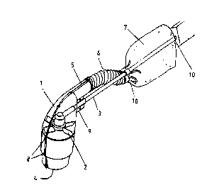
- fig.1 shows a prospective view of a suction device according to the
invention;
- flg.2 shows a second embodiment of the suction device of the invention;
2s - fig.s 3a,3b respectively illustrate a rear and a sectional view of the
device of the
invention having an adjustable joint.
Detailed description of the invention.
With reference to the annexed drawings, a suction device according to the
invention comprises a suction chamber 1 made of two half-parts, symmetrical
3o according to a longitudinal plane and joined by screws or other traditional
connecting means 8. Chamber 1 is placed around and laterally closes the
driving
shaft of a garden cutter and is fixed to its arm 3 by removable securing means
9,

CA 02271704 1999-OS-07
WO 98/19515 PCT/EP97/06133
3
for example screws means. Chamber 1 is a substantially hollow cylinder having
a
lower suction sleeve 4 opened at the bottom. On the rear side chamber 1 ends
with a second outlet sleeve 5 having dimensions correlated with these of
sleeve 4,
in order to optimize the suction efficiency. Sleeve 5 leads to a conveying
duct 6)
s preferably a flexible duct) through which the debris are conveyed up to a
collecting
bag 7 fixed to the garden cutter arm 3 by removable securing means 10.
Inside the chamber 1 a suction helix 2 connected in a traditional way to the
driving
shaft of the garden cutter can rotate. When operating, the rotation of the
helix 2
causes a suction effect by which the leaves and other debris which lay near to
the
io sleeve 4 are aspirated, cut by the same helix and conveyed into the
collecting bag
7. To increase the suction effect) the helix blades can be provided with end
brushes which touches the corresponding portion of the internal walls of
chamber
1.
Once the collecting bag has been filled it can be either emptied or replaced
by a
is new disposable bag.
In a preferred embodiment, means 8 and 9 of chamber 1 are screw means or
quick connections, while means 10 to fix bag 7 to the arm 3 are quick
connections,
for example a plastic open ring which can be elastically opened wide to be
placed
around the arm 3
ao Advantageously, most of the device's components (chamber 1, sleeves 4,5,
helix
2, bag 7) can be inexpensively manufactured by plastic moulding.
The engine and the handle of the garden cutter are not shown in the figures,
but it
is evident that a device according to the invention can be applied to any kind
of
rotating head garden cutter, powered by either fuel or electric engines, but
having
2s a driving shaft on which the helix can be mounted and a arm to
which the head 1 can be fixed.
As illustrated in figure 2, the chamber 1 shape is substantially flat and have
an
horizontal position.
' In this case, the chamber 1 is a shell-shaped case provided with an outlet
duct 5
3o which is placed lateral to the helix. A plurality of wheels 12 can be
mounted onto
the head 1 to ensure an adjustable distance of the head from the ground. This
embodiment is particularly suitable to use the device as a traditional suction

CA 02271704 1999-OS-07
WO 98/19S15 PCT/EP97/06133
4
device or a traditional lawn mower.
In the embodiment shown in fig.2, the helix 2 is constituted by a blade 11,
preferably a metal blade, which rotates close to the opening 4. The blade
shape is
specifically designed in order to both grind and suck the leaves and the other
s debris.
Figs 3a,3b show a device according to the invention in which the means
securing
the suction chamber 1 to the garden-cutter arm 3 are constituted by a
spherical
joint 91 comprising two symmetrical half-parts each built into the
corresponding
suction chamber half-part. Joint 91 is closed by traditional means around a
to substantially spherical body 31 which is fixed to the arm 3 in a
predetermined
position. The junction between joint 91 and spherical body 31 allows users of
any
height to adjust the angle formed between the plane of the opening of the
suction
chamber (which has to be kept horizontal) and the inclination of the arm the
most
appropriate for the user. In this embodiment, a box 92 is built in to the
chamber 1
is walls to house the safety shield which is usually placed over the rotating
blade or
wire of the garden-cutter and which is not removed from the arm when replacing
the rotating head with a helix according to the invention.

Representative Drawing
A single figure which represents the drawing illustrating the invention.
Administrative Status

2024-08-01:As part of the Next Generation Patents (NGP) transition, the Canadian Patents Database (CPD) now contains a more detailed Event History, which replicates the Event Log of our new back-office solution.

Please note that "Inactive:" events refers to events no longer in use in our new back-office solution.

For a clearer understanding of the status of the application/patent presented on this page, the site Disclaimer , as well as the definitions for Patent , Event History , Maintenance Fee  and Payment History  should be consulted.

Event History

Description Date
Inactive: IPC expired 2018-01-01
Inactive: IPC from MCD 2006-03-12
Application Not Reinstated by Deadline 2003-11-05
Time Limit for Reversal Expired 2003-11-05
Deemed Abandoned - Failure to Respond to Maintenance Fee Notice 2002-11-05
Inactive: Abandon-RFE+Late fee unpaid-Correspondence sent 2002-11-05
Letter Sent 2000-05-09
Reinstatement Requirements Deemed Compliant for All Abandonment Reasons 2000-04-27
Deemed Abandoned - Failure to Respond to Maintenance Fee Notice 1999-11-05
Inactive: Cover page published 1999-08-02
Inactive: IPC assigned 1999-07-05
Inactive: First IPC assigned 1999-07-05
Inactive: Notice - National entry - No RFE 1999-06-16
Letter Sent 1999-06-16
Application Received - PCT 1999-06-11
Application Published (Open to Public Inspection) 1998-05-14

Abandonment History

Abandonment Date Reason Reinstatement Date
2002-11-05
1999-11-05

Maintenance Fee

The last payment was received on 2001-10-24

Note : If the full payment has not been received on or before the date indicated, a further fee may be required which may be one of the following

  • the reinstatement fee;
  • the late payment fee; or
  • additional fee to reverse deemed expiry.

Patent fees are adjusted on the 1st of January every year. The amounts above are the current amounts if received by December 31 of the current year.
Please refer to the CIPO Patent Fees web page to see all current fee amounts.

Fee History

Fee Type Anniversary Year Due Date Paid Date
Basic national fee - standard 1999-05-07
Registration of a document 1999-05-07
Reinstatement 2000-04-27
MF (application, 2nd anniv.) - standard 02 1999-11-05 2000-04-27
MF (application, 3rd anniv.) - standard 03 2000-11-06 2000-10-19
MF (application, 4th anniv.) - standard 04 2001-11-05 2001-10-24
Owners on Record

Note: Records showing the ownership history in alphabetical order.

Current Owners on Record
ARNO PLAST S.R.L.
Past Owners on Record
DARIO AGLIETTI
PIERANTONIO BETTINI
Past Owners that do not appear in the "Owners on Record" listing will appear in other documentation within the application.
Documents

To view selected files, please enter reCAPTCHA code :


To view images, click a link in the Document Description column. To download the documents, select one or more checkboxes in the first column and then click the "Download Selected in PDF format (Zip Archive)" or the "Download Selected as Single PDF" button.

List of published and non-published patent-specific documents on the CPD .

If you have any difficulty accessing content, you can call the Client Service Centre at 1-866-997-1936 or send them an e-mail at CIPO Client Service Centre.


Document
Description 
Date
(yyyy-mm-dd) 
Number of pages   Size of Image (KB) 
Representative drawing 1999-07-28 1 6
Abstract 1999-05-06 1 54
Description 1999-05-06 5 216
Drawings 1999-05-06 2 40
Claims 1999-05-06 2 78
Reminder of maintenance fee due 1999-07-05 1 112
Notice of National Entry 1999-06-15 1 194
Courtesy - Certificate of registration (related document(s)) 1999-06-15 1 116
Courtesy - Abandonment Letter (Maintenance Fee) 1999-12-05 1 184
Notice of Reinstatement 2000-05-08 1 171
Reminder - Request for Examination 2002-07-07 1 128
Courtesy - Abandonment Letter (Maintenance Fee) 2002-12-02 1 176
Courtesy - Abandonment Letter (Request for Examination) 2003-01-13 1 167
PCT 1999-05-06 11 376
Fees 2001-10-23 1 35
Fees 2000-04-26 1 35
Fees 2000-10-18 1 31