Note: Descriptions are shown in the official language in which they were submitted.
CA 02271743 1999-OS-12
WO 98/22285 PCT/US97/21135
1
Thermal Joining of Webs
Christoph J. Schmitz
Field of the invention
The present invention relates to a method for the thermal joining of webs.
Its application is intended for use in disposable absorbent articles.
Background of the invention
Disposable absorbent articles, in particular, disposable diapers are well
known articles of manufacture which are designed to be worn principally by
infants and incontinence sufferers. Such diapers are worn about the lower
torso of the wearer and are intended to absorb and contain urine and other
bodily discharges) thus preventing the soiling, wetting, or similar
contamination of articles (e.g., clothing, bedding) other persons) etc.) that
may come into contact with such a diaper in use. In recent years,
disposable diapers in the form of pull-on diapers have emerged on the
market and in particular, disposable pull-on diapers with fixed sides have
gained in popularity. Typically, the fixed sides of the disposable pull-on
diaper are manufactured by joining the side panels of the front portion to the
side panels of the rear portion. For joining purposes, the contacting
surfaces of the side panels need to be at least partially melted. It is,
however, desirable to avoid melting the outer surfaces of the side panels
corresponding to the area to be joined. In general, a technique which
permits the joining of several layers of thick material that does not lead to
the formation of hard, raspy protuberances on the outer surfaces is
required. It has been documented that current techniques are more easily
suited to the joining of thin layers of material. Therefore, the problem of
joining thick materials is known in the art but the only solutions proposed
hitherto, as far as the present applicants are aware, are those described
hereforth.
Typical of prior art processes are the conventional thermal joining
processes, which utilise hot pins made of steel, aluminium and copper or
other materials with a high coefficient of thermal conductivity to transfer
the
required energy for melting into the webs to be joined. For thin materials
SUBSTITUTE SHEET (RULE 26)
CA 02271743 1999-OS-12
WO 98/22285 PCT/US97/21135
2
like films, the hot pins touch and melt the outer surfaces of the web
structure. For thicker materials, it is preferred that the hot pins penetrate
the whole web structure. The upward and downward action of the hot pins
results in both the creation of holes with molten walls and some of the
melted material being displaced and transported to the surface of the web
structure to form - after cooling - hard, raspy protuberances. In order to
ensure that an effective joining takes place, compression of the web
structure subsequently follows. Nevertheless, before the compression tools
can be placed in position, the hot pins have to be moved away resulting in a
complex operation. It is only when the melted material has cooled that the
compression tools are removed from the web structure.
The perforation of a film material generally, but not exclusively of,
thermoplastic material is taught in US 4,667,552. Heated perforation pins
are carried by a rotating cylinder and the film to be perforated is forced
against the pins by a pressure means such as a deformable roller. The hot
pin enters from the top of the plastic film and as the hot pin melts the
surrounding film after the pin perforates the film, the film is melted into an
'upset' structure. The film, after perforation, has one smooth face and an
obverse face that has a texture due to the proliferation of protuberances.
The technique is not suitable for the joining of thick materials.
US 4,519,798 typifies a process that utilises thermal energy to soften
two or more layers of thermoplastic material for the purposes of joining. The
patent discloses a disposable diaper structure wherein an absorbent core is
encapsulated between a multiplicity of sheets. Each of the sheets is
constructed of a material, such as polyethylene, which will heat seal without
the necessity of an adhesive. The diaper is made by heating and sealing
the overlapping edges of the polyethylene sheets directly to one another
outside the borders of the absorbent core.
The autogenous lamination of plural layers or laminae of sheet
material are described in US 4,919,738. In more detail, the patent teaches
a method of dynamically bonding plural laminae together, at least one of
which laminae comprises thermoplastic material. The lamination is
achieved through the use of pressure biased laminating rolls which are
operated with a predetermined surface velocity differential between them.
suBSrrurE sHe~r ~RU~E 2s~
CA 02271743 1999-05-12
WO 98/22285 PCT/US97/21135
3
Indeed, in some lamina, portions of the bonding sites may protrude resulting
in hard) raspy protuberances rather than being recessed.
Layers of thermoplastic materials are welded together by means of
ultrasonic vibration equipment in US 3,733,238. A plurality of spaced
ultrasonic vibration transmitting members having working surfaces in direct
contact with one side of the sheet-like elements is employed in co-operation
with opposing spaced anvil surfaces located on the opposite side of the
sheet-like elements to produce full width webs of thermoplastic laminated
material. As is evident, the technique requires that the layers of
thermoplastic material are always in direct physical contact with the
mechanical energy transfer tools) thus leading to contamination of the webs,
machine wear and thus machine inefficiency.
A seam composed of a six-layered structure comprising the outer
fabric layer, the inner impermeable layer of the cover sheet and the
permeable layer forming the liner of the garment is disclosed in
US 4,610,681. In order to form a small and unobtrusive bond, the ultrasonic
sealing is accomplished with a plurality of lines that form pressured areas
and raised line areas. As above, the technique is mechanical in nature and
results in contamination of the webs, machine wear and machine
inefficiency.
A means of joining thick layers of material is outlined in
US 4,909,804, which discloses seams of a disposable training pant that
have been joined by stitching.
WO 96/19313 describes a method for forming through apertures in
the form of holes andlor slits in a web that is intended to form part of an
absorbent article, e.g.) the topsheet of an absorbent article being apertured
to obtain liquid permeability. According to the invention, a web is irradiated
with at least one focused electromagnetic beam or particle beam from an
irradiating source on at least one of its surfaces and in those web regions
where the apertures are to be formed. During irradiation the web can be in
contact with another web which includes material of a kind similar to the
first
web and the properties of the beam and the duration of the irradiation
period are chosen so that the material in the first web andlor in the further
SUBSTITUTE SHEET (RULE 2B)
CA 02271743 1999-OS-12
WO 98/22285 PCT/US97I21135
4
web will be supplied with sufficient energy to join the webs in the immediate
vicinity of the apertures. A fluid may be delivered to the vicinity of the
focusing point on the web to remove moltenlburnedlvaporised material from
holes made in the web. In spite of the lack of contact with the webs to be
joined, the technique focuses on aperturing and results in melted material
being displaced and transferred to the topsheet surface.
Needlepunching is a mechanical bonding technique which is utilised
to join webs of material. In US 5,397,632, non-woven webs for use in an
improved automotive depth air filter are mechanically secured at intermittent
locations. During the needlepunching operation) a plurality of needles
having a fibre advancing configuration are passed through all the webs.
The various webs thus become mechanically interconnected and interlocked
through the entanglement of staple fibres and filaments. During such
needle insertion and withdrawal) staple fibres from the upper web and
relatively mobile fibres from the intermediate web are driven forward and
into the lower web. The surface of the final product is not smooth to the
touch.
As a result of the above prior art attempts, it has been recognised by
those skilled in the art that it would be desirable to provide a method of
joining thick webs for particular use in disposable absorbent articles that
eliminates the presence of hard) raspy protuberances on the outer surfaces
caused by the solidification of melted web material; that does not require the
use of heat transfer tools that come into physical contact with the webs to be
joined; that at least partially melts the meltable components in the web
structure to render a sufficient tackiness for joining; and that results in a
product with superior tactile properties and concomitant strength, resistance
to wear and breathability characteristics. The solution was found to be a
method wherein a high speed jet of heated fluid is directed into the outer
surface of at least two thick and porous webs at discrete locations and
wherein the constituent meltable components are at least partially melted in
the area of overlap of the web structure.
It has now been discovered that the benefits of the present invention
range from a method that enables the joining of thick, porous webs in an
extremely effective manner; to a method that eliminates the irritating hard
SUBSTITUTE StIEET (RULE 28)
_r __.. _. _ _T_ __ ._ ..__.
CA 02271743 1999-OS-12
WO 98/22285 PCT/US97/21135
and raspy protuberances of the prior art techniques; to a method that does
not rely on heat transfer tools coming in contact with and contaminating the
web structure as is typical of conventional joining processes; to a method
that minimises process time; to a method that leads to improved machine
efficiency due to reduced wear and friction; and to a product with enhanced
tactile qualities and superior resistance to wear characteristics leading to
improved consumer satisfaction and confidence.
Summary of the invention
A method of joining at least two webs is described. The webs are porous,
comprise meltable components and are arranged in an adjacent manner to
form a web structure. The web structure comprises outer surfaces and an
area of overlap joining the webs. The method is characterised by the steps
of:
1 ) sufficiently heating a fluid to enable at least a partial melting of the
meltable components;
2) directing a high speed jet of the heated fluid towards at least one outer
surface of the webs;
3) allowing the fluid to penetrate the webs at discrete locations; and
4) allowing the fluid to circulate in the webs to at least partially melt the
meltable components.
The method further comprises the step of compressing and cooling the web
structure while the meltable components are at least partially melted.
In particular, the method is used in the manufacture of disposable
absorbent articles. In a preferred embodiment of the invention, the method
is used to make the side seams of a pull-on diaper.
In a further aspect of the invention, a disposable absorbent article is
made according to the method described herein. The preferred embodiment
of this aspect of the invention describes a pull-on diaper with the webs
comprising the side panel of the front portion and side panel of the rear
portion, which are joined to form overlapping side seams) i.e.) the web
structure.
suesr~ure sHeEr iRU~ zs)
CA 02271743 1999-OS-12
WO 98/22285 PCT/IJS97/21135
6
Brief description of the drawings
It is believed that the invention will be better understood from the foregoing
description in conjunction with the accompanying drawings in which:
Figure 1 schematically illustrates a fragmentary side elevational view of the
webs;
Figure 2 shows a simplified schematic drawing of the apparatus used for
joining webs; and
Figure 3 illustrates a simplified and partially sectioned view of a cylinder
with a representative projection.
Detailed description of the invention
As used herein, the term "joining" encompasses the configuration whereby
an element is directly secured to another element by affixing the element
directly to the other element. As meant herein, the term "web" refers to a
layer of material(s). The term "layer" does not necessarily limit the web to a
single stratum of material. As used herein) the term "disposable" describes
absorbent articles that are not intended to be laundered or otherwise
restored or reused as an absorbent article (i.e., they are intended to be
discarded after a single use and, preferably, to be recycled, composted or
otherwise disposed of in an environmentally compatible manner. The term
"pull-on diaper" refers to a garment that is generally worn by infants and
sufferers of incontinence, which is pulled on like pants, and which is
intended to be discarded after a single use. It should be understood,
however, that the present invention is also applicable to other pull-on
diapers such as training pants, incontinence briefs) feminine hygiene
garments or panties, and the like.
A somewhat schematic, fragmentary side elevational view of the
webs to be joined is shown in Figure 1. In particular, Figure 1 shows at
least two porous webs 11, 12 that have been arranged in an adjacent
manner to form a web structure 10. The web structure 10 comprises outer
surfaces 13, 14 and an area of overlap 15 between the webs 11, 12.
SUBSTITUTE SHEET (RULE 26)
_.____ ____. _ _____._ _ T ___ _____
CA 02271743 1999-OS-12
WO 98/22285 PCT/US97/21135
7
The joining of webs is possible according to the teachings of the
present invention provided that at least one of the webs comprises sufficient
meltable material that is susceptible to being thermally joined to another
web. The present invention teaches webs that are porous - air permeable)
fluid permeable or vapour permeable - and that comprise meltable
components. The web can either be woven or non-woven and the meltable
components may comprise fibres or polymeric binders and can include
natural fibres such as cellulose - wood pulp, cotton, jute, hemp; synthetic
fibres such as fibreglass, rayon, polyester, polyolefin, acrylic) polyamid,
aramid, polytetrafluroethylene metal, polyimide; and binders such as
bicomponent high melt/low melt polymer, copolymer polyester, polyvinyl
chloride, polyvinyl acetatelchloride copolymer, copolymer polyamide. The
webs may additionally comprise blends of materials wherein some of the
constituent materials are not meltable.
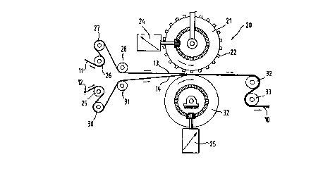
Figure 2 shows a simplified schematic drawing of the apparatus used
for joining webs 11, 12 to form a web structure 10 in accordance with the
method of the present invention. The apparatus 20 comprises a cylinder 21
with projections 22; an anvil cylinder 23; a means 24, 25 for rotating the
cylinders 21, 23; and rolls 26 to 33, inclusive, for guiding and advancing the
webs 11, 12 through and away from the point at which energy transfer
occurs. It should be noted that there is no need to heat the cylinder 21 and
anvil cylinder 23. The apparatus 20 additionally comprises a frame (not
shown); a fluid jet nozzle leading to the projections 22 (not shown); a
temperature control means (not shown) for heating up the fluid; a pressure
means (not shown) for regulating the pressure of the fluid; and means (not
shown) for driving the rolls 26 to 33 for controllably forwarding webs 11, 12
through the point at which the energy transfer occurs and for enabling the
resulting web structure 10 to be forwarded to downstream apparatus such
as a single pad handling apparatus, which tucks in the fixed sides of the
diapers.
For clarity of the present invention, neither the upstream ends or
sources of webs 11, 12, nor the downstream destination or user of the web
structure 10 are shown. Nevertheless, it is well known to provide webs in
roll form; and to provide upstream unwinding and splicing means to enable
forwarding continuous lengths of such webs through joining means and or
SUBSTITUTE SHEET (RULE 26j
CA 02271743 1999-OS-12
WO 98/22285 PCT/US97/21135
8
converters to make web structures. For simplicity of the present invention,
the apparatus 20 is described herein as comprising a cylinder 21 and an
anvil cylinder 23. It is not intended in any way to limit the invention to an
apparatus comprising cylinders per se.
Figure 3 shows a simplified and partially sectioned view of the
cylinder 21 with a representative projection 22. The cylinder 21 comprises
either a conical or cylindrical shaped zone 34 through which the fluid
required to at least partially melt the meltable components of the webs 11,
12 is directed. In Figure 2, for simplicity, a cylindrical shaped zone 34 is
drawn. A fluid jet nozzle (not shown) is connected to the top face 35 of a
conical or cylindrical shaped zone 34. The fluid is preferably air although
other gases may be used. In addition, use can be made of energetic fields
to achieve the same partial melting effect. In the present invention, the
fluid
is heated up to a temperature ranging from the melting point of the material
minus 30 degrees Celsius to the melting point of the material plus 100
degrees Celsius. The pressure ranges from 0.1 E5 Newtons per square
metre to 10E5 Newtons per square metre. The diameter at the top face 35
of the conical or cylindrical shaped zone 34 ranges from 1 millimetre to 8
millimetres and the diameter of the orifice 36 of the conical or cylindrical
shaped zone 34 ranges from 0.1 millimetres to 6 millimetres. The conical or
cylindrical shaped zone 34 moves preferably with the same or almost same
speed as the area of overlap 15 of the webs 11, 12 for an extended time
interval ranging from 10 to 1000 milliseconds. This enables the heated fluid
to be directed towards at least one outer surface 13, 14, as required, to
achieve optimum quality seams in terms of strength and softness. The
projections 22 on the cylinder 21 may be disposed in a predetermined
pattern: each projection being configured and disposed to precipitate areas
of overlap 15 in the webs 11, 12 to be joined to effect a predetermined
pattern of areas of overlap 15 in the web structure 10. The cylinder 21 may
have a saw-tooth shape pattern of projections 22 which extend
circumferentially about each end of the cylinder 21.
The anvil cylinder 23 is preferably a smooth, surfaced, right circular
cylinder of steel, which can be independently power rotated by a speed
controlled direct current motor. In an alternative configuration) the anvil
cylinder 23 moves preferably with the same speed as the webs 11, 12 at the
SUBSTITUTE SHEET (RULE 26)
CA 02271743 1999-OS-12
WO 98/22285 PCT/US97/21135
9
area of overlap 15 for an extended period of time ranging from 20 to 1000
milliseconds. During this time interval, the area of overlap 15 is deformed,
joining occurs and cooling follows. There may also be a number of anvils
and fluid jet nozzles mounted on a carrier at a pitch ranging between 0.5
and 1.5 times the product pitch.
The means 24, 25 are provided to drive the cylinder 21 and anvil
cylinder 23. Therefore, they constitute drive means for power rotating the
cylinder 21 and anvil cylinder 23 so that there is a predetermined but
adjustable relationship between their surface velocities. This can be
synchronous, asynchronous: equal surface velocities; or with a
predetermined surface velocity differential with either cylinder 21 or anvil
cylinder 23 being driven faster than the other. The rolls 26 to 33, inclusive,
are driven at surface velocities which maintain predetermined levels of
tension or stretch so that neither slack web conditions nor excessively
tensioned/stretched webs precipitate undesirable deleterious
consequences.
According to the inventive method of the present invention, the
joining of at least two webs 11, 12 that are arranged in an adjacent manner
to form a web structure 10 as illustrated in Figure 1 comprises the following
steps of: sufficiently heating a fluid to enable at least a partial melting of
the
meltable components; directing a high speed jet of the heated fluid towards
at least one outer surface 13, 14; allowing the fluid to penetrate the webs
11, 12 at discrete locations; and allowing the fluid to circulate in the webs
11, 12 to at least partially melt the meltable components. The heated fluid,
at a preferred temperature and pressure, passes from the fluid jet nozzle
into the conical or cylindrical shaped zone 34 of the projection 22 and out
through the orifice 36, leading to the formation of controlled and
concentrated jets of heated fluid, which are directed towards the outer
surfaces 13) 14 of the webs 11) 12 to be joined. The fluid can also be
delivered to the outer surfaces ~ 3, 14 by means of a pulsed application.
The impact of the jet of heated fluid is adjusted such that both the energy
introduced by the jet per se plus the energy introduced by other means such
as the heated anvil (if this is the case), jet nozzle surface) deformation of
the
webs 11, 12, and the internal friction of the webs 11, 12 are sufficient to at
least partially melt the meltable components in the webs 11, 12 to create a
SUBSTITUTE SHEET (RULE 28)
CA 02271743 1999-OS-12
WO 98/22285 PCT/US97/21135
certain tackiness, which will form a strong join at the area of overlap 15
upon compression. The melting of the meltable components occurs in a
non-uniform manner throughout the webs 11, 12. In particular, the exterior
surface of the meltable components begins to melt leaving the interior of the
meltable components in the solid state. As a consequence of the exterior
melting of the meltable components, a certain tackiness is created.
The method further comprises the step of compressing the web
structure 10 with compression tools while the meltable components are at
least partially melted, i.e., in the tacky state. This is achieved by applying
pressure to the web structure 10 using compression tools. The temperature
of the compression tools is at least below the melting point of the web
structure 10. The tackiness property of the meltable components permits
the joining of the webs 11, 12 and thus, the accumulation of melted web
material is avoided. Such melted material typically forms the hard, raspy
protuberances on the outer surfaces of so many web structures upon
solidification. The compression tooling can be designed according to
aesthetic criteria.
Good results are obtained with this method on non-woven webs
ranging from 30 to 500 grams per square metre containing fibres ranging
from microfibres of less than one denier to conventional fibres ranging from
1 to 7 denier. The non-woven webs may also contain scrim materials
having strands with diameters greater than 1 millimetre. Due to the
thickness of the webs) the interval of time required to affect the webs 11, 12
with this technique ranges from 100 to 1000 milliseconds. In this particular
application, 100 to 150 milliseconds is required for heating and 150 to 250
milliseconds is required for compressionlcooling.
In a further aspect of the present invention, the method as described
hereinabove is used in the manufacture of disposable absorbent articles. In
particular, the method is preferably used in the making of side seams for
disposable absorbent articles wherein the disposable absorbent articles are
disposable pull-on diapers. A disposable pull-on diaper, made according to
the method of the present invention, has an outer surface, an inner surface,
a front portion) a rear portion, a crotch portion, each of said front portion
and said rear portion having side panels with side edges and overlapping
su~s~ sHe» iRU~ 2s~
CA 02271743 1999-OS-12
WO 98/22285 PCT/US97/21135
11
side seams which join together the side panels of the front portion and the
rear portion to form leg openings and a waist area. The pull-on diaper thus
preferably comprises a chassis layer; an elastically extensible stretch
laminate positioned in each side panel of the front portion, front stretch
laminates; an elastically extensible stretch laminate positioned in each side
panel of the rear portion) rear stretch laminates; and at least one
elasticised
waistband positioned in both the front portion and the rear portion. The
pull-on diaper comprise leg openings which additionally comprise elastic leg
features to improve fit at the legs in the crotch portion.
The pull-on diaper has a crotch portion comprising a main panel and
a pair of leg flap panels. The absorbent core is generally positioned within
the main panel of the crotch portion since bodily exudates are typically
discharged in this area. A leg flap panel extends generally laterally
outwardly from and along each side edge of the main panel. Each leg flap
panel generally forms at least a portion of the elastic leg feature. The outer
surface of the pull-on diaper comprises that portion which is positioned
away from the body of the wearer during use. The inner surface of the
diaper is opposed to the outer surtace and comprises that portion of the
diaper which is positioned adjacent to the body of the wearer during use.
Elastically extensible stretch laminates (front stretch laminates and
rear stretch laminates) are formed in each side panel of both the front
portion and the rear portion. Each stretch laminate is mechanically
stretched or drawn to allow the stretch laminate to be elastically extensible
in at least the lateral direction. (The lateral direction (x direction or
width) is
defined as the direction parallel to the lateral centreline of the pull-on
diaper. The side panels are preferably an extension of the chassis layer
and other elements such as the topsheet, or any other combination of these
elements. In the overlapping side seams, the stretch laminate is preferably
activated by mechanical stretching to provide additional extensibility in this
region. The overlapping side seams may also not be activated by
mechanical stretching.
In order to provide the necessary absorbency to contain bodily
discharges) the pull-on diaper comprises a liquid pervious topsheet and an
absorbent core positioned between the topsheet and the chassis layer. The
SUBSTITUTE SHEET (RULE 28)
CA 02271743 1999-OS-12
WO 98/22285 PCT/US97I21135
12
topsheet is positioned adjacent to the body surface of the absorbent core
and is preferably joined to the absorbent core and the chassis layer by
attachment means such as those well known in the art. In a preferred
embodiment, the topsheet and the chassis layer are indirectly joined
together by directly joining them to the absorbent core or the elastic panel
members or other elements of the pull-on diaper. The topsheet preferably
comprises three distinct layers joined together. A liquid pervious primary
layer is positioned over the absorbent core to rapidly absorb liquids into the
product. Barrier layers are joined to the primary layer and are preferably
drawable, more preferably hydrophobic, to allow the side panels to be
mechanically stretched without ripping or tearing while providing barrier
cuffs along the sides of the pull-on diaper. The elastic leg features
preferably comprise a gasketing cuff and a barrier cuff. The gasketing cuff
is preferably formed by one or more elastic leg members operatively joined
to the chassis layer, the barrier layer, or both, preferably between the
chassis layer and the flap portion of the barrier layer in the leg flap panel
of
the crotch portion. The barrier cuff is preferably formed by a flap (the stand-
up portion of the barrier layer, closing means for securing the longitudinal
ends of the stand-up portion to the primary layer, and an elastic spacing
member operatively joined to the stand-up portion.
The primary layer is preferably compliant, soft feeling, and non-
irritating to the skin of the wearer. The primary layer is liquid pervious
permitting liquids (e.g., urine) to readily penetrate through its thickness. A
suitable primary layer may be manufactured from a wide range of materials,
such as porous foams; reticulated foams; apertured plastic films or three
dimensionally expanded formed films; or woven or nonwoven webs of
natural fibers, synthetic fibers, or a combination of natural and synthetic
fibers. The primary layer is preferably non-coterminous with the chassis
layer so that liquid will not wick along and through the primary layer to the
edges of the pull-on diaper, so that liquids will not wick underneath and
beyond the stand-up barrier cuffs formed by the barrier layers, and so that
more drawable materials may be positioned in the side panels to produce
stronger stretch laminates. The primary layer preferably overlays a major
portion of the body surface of the absorbent core, more preferably all of the
body surface area of the absorbent core in at least the crotch portion, so
that exudates that are discharged into the pull-on diaper penetrate through
SUBSTITUTE SHEET (RULE 26)
CA 02271743 1999-OS-12
WO 98/22285 PCT/US97/21135
13
the primary layer where they are absorbed by the absorbent core. The
primary layer extends laterally outwardly toward the side edges of the
absorbent core, preferably beyond the side edges of the absorbent core in
at least the crotch portion. The primary layer, however, terminates inwardly
of the leg edges of the crotch portion. In the most preferred configurations,
the primary layer terminates adjacent the proximal edge of the barrier layer
(i.e., the terminating edge of the primary layer is positioned adjacent to the
proximal edge) or the terminating edge is positioned remotely from and
inboard of the proximal edge. "Adjacent" is used in this context to mean
that the primary layer terminates at the proximal edge plus or minus small
areas of the primary layer material that may extend inside or beyond the
proximal edge due to machine tolerances during manufacture or variations
in the area of the primary layer when it is manufactured. In the preferred
embodiment of the topsheet, the barrier layers form the elastic leg features
(preferably, a gasketing cuff and/or a barrier cuff) and, preferably, a
portion
of the stretch laminates.
The chassis layer preferably comprises a continuous sheet or web
which defines the front portion, the rear portion, and the crotch portion.
Thus, the chassis layer is the primary stratum or layer of the pull-on diaper.
(As used herein, the term "layer" does not necessarily limit the element to a
single stratum of material in that a layer may actually comprise laminates or
combinations of sheets or webs of the requisite type of materials.) The
chassis layer has an inner surface and an outer surface. The inner surface
and outer surface of the chassis layer correspond in their orientation to the
inner surface and the outer surface of the pull-on diaper.
The chassis layer generally determines the overall shape of the pull-
on diaper. The chassis layer acts as the main structural layer of the pull-on
diaper to which other features may be added or joined. The chassis layer is
thus positioned in all or most of the surface area of the pull-on diaper,
although in certain embodiments certain portions of the chassis layer may
be apertured, cut-out or removed ("windowed") to enhance stretchability
andlor breathability of the pull-on diaper or features of the pull-on diaper
in
that area. The chassis layer thus may comprise a continuous sheet or web
that does not have "joints" or seams such that forces are distributively
transmitted through the entire layer or the chassis layer may comprise a
suesmurlr sHE~ ~u~e 2s~
CA 02271743 1999-OS-12
WO 98/22285 PCT/US97/21135
14
continuous sheet or web that does have "joints" with the elasticised leg
cuffs. As previously discussed herein, the continuous sheet or web of the
chassis layer can comprise a single web of material or a laminate of several
continuous webs or layers of different materials. The chassis layer may
form the outer surface, the inner surtace, or portions of either or both, or
may be entirely positioned in the interior of the pull-on diaper. The chassis
layer preferably forms the outer surface of the pull-on diaper in the crotch
portion.
Since at least a portion of the chassis layer is subjected to
mechanical stretching in order to provide the stretch laminates in the side
panels, it is preferably elongatable, more preferably drawabie (but not
necessarily elastomeric)) so that the chassis layer will, upon mechanical
stretching, be at least to a degree permanently elongated such that it will
not fully return to its original undistorted configuration. The chassis layer
may thus comprise any of the materials known for use in absorbent articles
such as woven or nonwoven webs; polymeric films such as thermoplastic
films of polyethylene, polypropylene, or blends thereof; laminates of such
materials; or composite materials. In preferred embodiments, the chassis
layer can be subjected to mechanical stretching with minimal or no rupturing
or tearing. Therefore, the chassis layer is preferably a polymeric film.
Due to the fact that the chassis layer is preferably a polymeric film) it
is also generally impervious to liquids (e.g., urine) so that it may also
serve
as the component which prevents bodily discharges absorbed and
contained in the absorbent core from wetting garments which contact the
pull-on diaper 10 such as bed sheets and undergarments (i.e., it acts as the
traditional diaper backsheet). If the chassis layer is not liquid impervious,
typically an additional layer such as a traditional backsheet should be used
behind the absorbent core. The chassis layer may also be breathable
(pervious to air or water vapour) if desired. The chassis layer can
alternatively comprise breathable materials that are microporous and that
are, typically) lower in strength and elongation. An example of such a film is
that manufactured by Exxon Chemical Company under the tradename
EXXAIRE. Exemplary films for use as the chassis layer of the present
invention having relatively good drawability but that are not breathable
include polymeric films manufactured by Clopay Corporation of Cincinnati,
8U98TITUTE SHEET (RULE 26)
CA 02271743 1999-OS-12
WO 98/22285 PCT/US97/21135
Ohio under the designation Clopay 1401, or films available from Tredegar of
Terre Haute, Indiana, under the designation X-8323 or X-9954.
The pull-on diaper comprises a leg area that comprises elasticised
leg cuffs for providing improved containment of liquids and other bodily
exudates. The elastic leg features provide improved containmerit of liquids
and other body exudates in the crotch portion and about the leg openings in
general. Each elastic leg feature may comprise several different
embodiments for reducing the leakage of body exudates in the leg flap
panels (the elastic leg feature can be and is sometimes also referred to as
leg bands, side flaps, barrier cuffs, or elastic cuffs.)
US 3,860,003 describes a disposable diaper which provides a contractible
leg opening 16 having a side flap and one or more elastic panel members to
provide an elasticized leg cuff (gasketing cuff).
US 4,909,803 discloses a disposable diaper having "stand-up" elasticized
flaps (barrier cuffs) to improve the containment of the leg regions.
US 4,695,278 teaches a disposable diaper having dual cuffs including a
gasketing cuff and a barrier cuff. US 4,795,454 discloses a disposable
diaper having leakage resistant dual cuffs wherein the topsheet stops short
of. the side edge of the diaper to prevent wicking out to the side of the
garment. While each elastic leg feature may be configured so as to be
similar to any of the leg bands, side flaps, barrier cuffs or elastic cuffs
described above, it is preferred that each elastic leg feature comprise a
combination of a gasketing cuff and a barrier cuff. The gasketing cuff and
barrier cuffs are preferably formed as shown in US 4,795,454.
The absorbent core is preferably positioned adjacent to the inner
surface of the chassis layer and is preferably joined thereto by attachment
means such as those well known in the art. For example) the chassis layer
may be secured to the absorbent core by a uniform continuous layer of
adhesive, a patterned layer of adhesive, or an array of separate lines)
- spirals) or spots of adhesive. Alternatively, the attachment means may
comprise heat bonds, pressure bonds, ultrasonic bonds, dynamic
mechanical bonds, or any other suitable attachment means or combinations
of these attachment means as are known in the art. It may also be possible
to apply the method of the present invention to join the chassis layer to the
absorbent core.
SU88TITUTE SHEET (RULE 26)
CA 02271743 1999-05-12
WO 98/22285 PCT/US97/21135
16
The absorbent core may be any absorbent means which is generally
compressible, conformable) non-irritating to the skin of the wearer) and
capable ~of absorbing and retaining liquids such as urine and other certain
bodily discharges. The absorbent core may be manufactured in a variety of
sizes and shapes (e.g., rectangular) hour-glass, 'T"-shaped, asymmetric,
etc.) and from a wide variety of liquid absorbent materials commonly used in
disposable diapers and other absorbent articles such as comminuted wood
pulp which is generally referred to as airfelt. Examples of other suitable
absorbent materials include creped cellulose wadding, meltblown polymers
including coform, crosslinked cellulosic fibers, tissue including tissue
wraps,
absorbent foams, absorbent sponges, superabsorbent polymers, absorbent
gelling materials) or any equivalent materials or combinations of materials.
The configuration and construction of the absorbent core may also be
varied (e.g., the absorbent core may have varying caliper zones, hydrophilic
gradients, superabsorbent gradients) or lower average density and lower
average basis weight acquisition zones; or may comprise one or more
layers or structures). The total absorbent capacity of the absorbent core
should, however, be compatible with the design loading and the intended
use of the pull-on diaper. Further) the size and absorbent capacity of the
absorbent core may be varied to accommodate wearers ranging from
infants through adults.
in general, the absorbent core has an asymmetric, modified
hourglass shape and has a body surtace toward the body of the wearer
(inner surface) and a garment surface opposite the body surface. An
exemplary absorbent structure for use as the absorbent core of the present
invention that has achieved wide acceptance and commercial success is
described in US 5,360,420. Preferably, the absorbent core will comprise an
acquisitioNdistribution layer of chemically stiffened cellulosic fibers and a
storage layer positioned beneath the acquisition/distribution layer
comprising a mixture of wood pulp fibers and superabsorbent material such
as are disclosed in US 4,610,478.
The pull-on diaper can also be preferably provided with vents or
apertures to permit the passage of .air and water vapour to and from the
interior of the pull-on diaper. In a preferred embodiment, the apertures are
SUBSTITUTE SHEET (RULE 26)
CA 02271743 1999-OS-12
WO 98/22285 PCT/(JS97/21135
17
positioned in the side panels. In this configuration, bodily discharges are
prevented from leaking out of the areas adjacent to the absorbent core but
air and water vapour are allowed to be exchanged in the product to ventilate
it so that the product does not become excessively wetted by body
perspiration and uncomfortable to wear. Vents may additionally be provided
in other panels of the pull-on diaper or on certain of the features of the
pull-
on diaper such as the waistband. Breathability may alternatively be
provided by making the materials of the pull-on diaper out of porous
materials such as are known in the art. For example, the chassis layer
could comprise a breathable (vapour permeable) but liquid impervious
plastic film. The elastic panel members may be open material such as
foams, scrims, nonwovens, or breathable elastomeric films to further
enhance the breathability of the pull-on diaper. The overlapping side
seams retain good breathability properties if manufactured according to the
method of the present invention. The waistband can also be breathable to
allow water vapour to escape from the front portion and the rear portion of
the pull-on diaper. Breathability may be provided in the waistband by
selecting relative breathable materials for its construction andlor by
aperturing or venting the waistband such as is discussed herein with
respect to the stretch laminates in the side panels. In another embodiment,
the waistband may be hydrophobic, hydrophilic, or a combination
hydrophobiGhydrophilic member. A hydrophilic waistband may be used to
pull moisture away from the skin of the wearer to keep the skin from
becoming hydrated. Alternatively, a hydrophobic waistband may be used to
prevent fluid absorbed by the diaper from leaking out through the waist
opening. A combination hydrophobidhydrophilic waistband may be used to
prevent fluid absorbed by the diaper from leaking out through the waist
opening while also pulling moisture away from the skin of the wearer to
keep the skin from becoming hydrated.
In general, seams for disposable pull-on diapers can be formed by
joining the side panels of the front portion to the side panels -of the rear
portion. According to a preferred embodiment of the present invention, the
disposable pull-on diaper comprises the side panel of the front portion and
the side panel of the rear portion. The side panels are joined to form
overlapping side seams) i.e.) a web structure 10, according to the method
outlined herein.
SU9STLT<JTE SHEET (RULE 28)