Note: Descriptions are shown in the official language in which they were submitted.
CA 02271881 1999-05-11
WO 98/22842 PCT/GB97/03157
I
' OPTICAL FIBRE ORGANIZER
The present invention relates to the organization of optical fibres, e.g. in
an
optical fibre cable splice closure.
Many different designs of optical fibre organizer are known. For example,
WO 95/07480 (Raychem) discloses a base for an optical fibre organizer, which
comprises: a first passage along one longitudinal edge portion for incoming
fibres; a
second passage along an opposite longitudinal edge portion for outgoing
fibres; a
plurality of first fibre guides separated from one another along the length of
the base
and extending from the first passage across the base towards the second
passage
where fibres in said guides are directed away from the plane of the base; a
plurality of
second fibre guides separated from one another along the length of the base
and
extending from the second passage across the base towards the first passage
where
fibres in said guides are directed away from the plane of the base.
WO 95/25978 (Raychem) discloses an apparatus for arranging a plurality of
stacks of optical fibre splice organizers in a closure, comprising a frame and
at least
two optical fibre splice organizer supports located on the frame, each
organizer
support being arranged to support a stack of organizers. The frame may be
elongate
and the organizer supports may each support a stack of organizers which
extends
laterally with respect to the frame. The organizer supports may be in one or
more
pairs, the supports of each pair being arranged back-to-back.
WO 95/07475 (British Telecom) discloses an optical fibre management system
comprising a plurality of splice trays arranged in a stack. Each splice tray
has a main
body portion for holding at least one splice, and for storing fibres leading
to the
splice(s), and a fibre entry/exit portion for feeding fibre to/from the main
body
II ~ ~
CA 02271881 1999-05-11
WO 98/21955 PCT/I1S97/21357
2
portion. Each tray is mounted in the stack so as to be movable from a stacked
position, in which it is aligned with the other trays, to first and second
operating
positions in which the fibre entry/exit portion and the main body portion
respectively
are accessible. A related patent application, WO 95/07486 (British Telecom),
discloses so-called "single circuit management" of spliced fibres or unspliced
cut dark
"customer" fibres. Single circuit management is the management of optical
fibres by
separating individual optical fibre circuits from each other.
GB-A-2305739 (Telephone Cables Limited) discloses an optical fibre splice
tray which comprises a body with a plurality of splice holders at fixed
locations.
Fibre paths are provided on the body leading from fibre entry points to the
splice
holders. Hinged storage leaves are also mounted on the body.
According to a first aspect, the invention provides an optical fibre organizer
for organizing a plurality of uncut optical fibres of an optical fibre cable,
comprising a
plurality of optical fibre storage trays, the construction of the organizer
being such
that:
(a) the uncut optical fibre(s) of each single optical fibre circuit; or
(b) the uncut optical fibres of each single optical fibre cable element;
may be stored separately from the optical fibre(s) of each other circuit or
element (as
the case may be) on respective individual storage trays.
The invention also provides such an organizer in which the uncut optical
fibres
are (i.e. have been) so installed on the storage trays.
According to a second aspect, the invention provides a method of organizing a
plurality of uncut optical fibres of an optical fibre cable, on an optical
fibre organizer,
the organizer comprising a plurality of optical fibre storage trays, the
method
comprising storing:
(a) the uncut optical fibre(s) of each single optical fibre circuit; or
(b) the uncut optical fibres of each single optical fibre cable element;
CA 02271881 1999-05-11
WO 98/21955 PCT/US97/21357
3
separately from the optical fibre(s) of each other circuit or element (as the
case may
be) on respective individual storage trays.
By "uncut" optical fibres is meant optical fibres which enter and exit the
organizer without being severed. Such fibres are sometimes referred to as
"express"
fibres, since they extend through the organizer without being spliced,
connected or
broken for any other reason. The invention has the advantage that, for the
first time, it
enables such uncut fibres to be stored in single circuits, or single cable
elements (as
the case may be). This is advantageous because the fibre(s) of individual
circuits or
cable elements which are not spliced to other fibres when the organizer is
initially
installed on the cable may later be spliced to other fibres without disturbing
the uncut
fibres of other circuits or cable elements (as the case may be). This vastly
reduces the
risk of accidentally introducing signal losses into the circuits, or cable
elements, of
other uncut fibres, or damaging the other uncut fibres, during the splicing
procedure.
The splicing of fibres which had initially remained uncut (and unspliced) is
carried
out, for example, when adding new subscribers, or new services, to the
network.
In contrast with the present invention, the various optical fibre organizers
disclosed in the prior publications mentioned earlier, are incapable of
storing uncut
fibres in single circuits or single cable elements. For example, the optical
fibre
management system disclosed in WO 95/07486 is able to store only severed
optical
fibres (i.e. spliced fibres or unspliced dark "customer" fibres). This is
because the
fibres which are stored in single circuits must have their ends threaded
through
openings which are closed in cross-section. Uncut fibres are instead retained
bundled
in their cable tubes which are in turn bundled together and looped around the
so-called
= break-out tray. Similarly, the splice tray arrangement of GB-A-2305739
requires the
optical fibre ends to be threaded through holes punched in the hinged leaves
(see Fig.5
= of that document).
For the avoidance of doubt, it should be noted that a single circuit may, for
example, comprise a single optical fibre or a pair of optical fibres,
depending upon the
CA 02271881 1999-05-11
WO 98/21955 PCT/US97/21357
4
transmission technique used. Also, a cable element is a defined group of
optical fibres
in a cable, for example a group of fibres from a single tube of the cable, or
a group of
fibres from a single slot of a slotted core cable.
In a preferred embodiment of the invention, the construction of the organizer
is such that it comprises a plurality of optical fibre guides intended for
uncut optical
fibre(s), every one of which is open or openable in transverse cross-section,
thereby
permitting side-entry of the uncut optical fibre(s) into the guide.
The organizer may advantageously further comprise a support which
comprises:
(i) a plurality of tray mounting means to which the optical fibre storage
trays are attached, thereby mounting the trays on the support; and
(ii) a plurality of guides for guiding the optical fibre(s), the or each said
guide being open or openable in transverse cross-section, thereby permitting
side-entry into the guide of optical fibre(s) extending from a respective
optical
fibre storage tray mounted on the support.
According to a third aspect, the invention provides an optical fibre organizer
which comprises a support, the support comprising:
(i) one or more tray mounting means for attachment to at least one optical
fibre storage tray, thereby to mount the tray on the support; and
(ii) at least one guide for guiding at least one optical fibre, the or each
said
guide being open or openable in transverse cross-section thereby
permitting side-entry into the guide of at least one optical fibre extending
from a respective optical fibre storage tray mounted on the support.
~--
CA 02271881 1999-05-11
WO 98/21955 PCT/US97/21357
The mounting means may be separate or separable from the guide(s). More
preferably, however, the mounting means is/are integrally formed (e.g.
moulded) with
the guide(s).
According to a fourth aspect, the invention provides an optical fibre
organizer
which comprises a unitary support, the support comprising:
(i) one or more tray mounting means for attachment to at least one optical
fibre storage tray thereby to mount the tray directly on the support; and
(ii) a least one guide for guiding at least one optical fibre extending, in
use,
from an optical fibre storage tray mounted on the support.
The or each guide of the fourth aspect of the invention is preferably open or
openable in transverse cross-section in use, thereby permitting side-entry
into the
guide of a least one optical fibre extending from a respective optical fibre
storage tray
mounted on the support.
The support preferably comprises a plurality of guides. Additionally or
alternatively, the support may comprise a plurality of tray mounting means for
attachment to a plurality of optical fibre storage trays thereby to mount the
trays on
the support. In preferred embodiments, therefore, the organizer comprises a
plurality
of said optical fibre storage trays, each of which is attached to at least one
said tray
mounting means, the trays thereby being mounted directly on the support.
The or each tray mounting means is preferably arranged with respect to at
least
one respective guide such that at least one optical fibre extending, in use,
from a
storage tray attached to one or more tray mounting means may be guided by the
or
each respective guide without the optical fibre being bent below its critical
bend
radius. Advantageously the or each guide may include at least one ramp
arranged to
guide at least one optical fibre between the guide and an optical fibre
storage tray
CA 02271881 2006-11-29
27065-379
6
attached, in use, to the respective tray mounting means.
The or each guide preferably includes at least two ramps,
for example four ramps.
In preferred embodiments, each guide preferably
comprises at least one groove in the support.
Each guide may advantageously be arranged such
that at least part of it is substantially parallel to the or
each optical fibre storage tray mounted, in use, on the
support. Preferably, the support further comprises at least
one routing means arranged substantially perpendicularly to
this part of the or each guide, for routing one or more
optical fibres from the guide(s) to the exterior of the
support. The routing means may, for example, comprise at
least one channel.
The support is preferably in the form of a plate.
The organizer most preferably comprises a
plurality of supports, preferably attachable either directly
or indirectly together side-by-side to form a larger
support. Advantageously, this indirect attachment may be by
means of a support frame to which the supports are
attachable side-by-side to form a larger support.
According to a fifth aspect, the invention
provides a kit of parts for forming an optical fibre cable
closure, comprising an optical fibre organizer according to
the previously mentioned aspects of the invention, and a
casing for enclosing the optical fibre organizer. The
casing preferably comprises a base containing cable ports,
and a generally dome-shaped cover attachable to the base,
the optical fibre organizer being attachable to the base.
CA 02271881 2006-11-29
27065-379
6a
According to one aspect of the present invention,
there is provided a method of organizing a plurality of
uncut optical fibres of an optical fibre cable, the method
comprising (i) providing an optical fibre organizer having a
plurality of optical fibre storage trays incorporating a
plurality of optical fibre guides intended for uncut optical
fibre(s), every one of which guides is open or openable in
transverse cross-section, thereby permitting side-entry of
the uncut optical fibre(s) into the guides; and (ii) side-
entering and storing the uncut optical fibre(s) of each
single optical fibre circuit or cable element individually
into a respective storage tray separately from the optical
fibre(s) of each other circuit or element on other
respective individual storage trays.
According to another aspect of the present
invention, there is provided an optical fibre organizer for
use in a method of organizing a plurality of uncut optical
fibres of an optical fibre cable according to any preceding
claim, the organizer comprising a plurality of optical fibre
storage trays, and the construction of the organizer being
such that the uncut optical fibre(s) of each single optical
fibre circuit or cable element may be stored separately from
the optical fibre(s) of each other circuit or element, on
respective individual storage trays.
The invention will now be described, by way of
example, with reference to the accompanying drawings, of
which.
CA 02271881 1999-05-11
WO 98/21955 PCT/US97/21357
7
Figures 1 A-1 C show a support according to the invention, for hinged optical
fibre storage trays;
Figures 2A-2B show another support according to the invention, for hinged
optical fibre storage trays; and
Figure 3 shows an assembled optical fibre organizer according to the invention
attached to a base of a cable closure.
Figure 1 shows a modular support plate I comprising a plurality of parts of
mounting means 3 in the form of integral moulded protrusions standing up from
the
plate. The mounting means 3 contain apertures for receiving hinge pins formed
on the
storage trays. The storage trays are therefore hinged with respect to the
support plate
in use. Each of the trays may therefore be accessed by pivoting all of the
trays on one
side of the tray, away from the tray. Figure 1 also shows flexible tines 4
(also
protruding from the support plate) which lock the hinge pins of the trays in
the
mounting pins 3.
Each pair of mounting means 3 is associated with a respective guide 5 which
is in the form of an open-sided groove in the plate. In use, an optical fibre
storage tray
7 (see Figure 3) is attached to a particular pair of mounting means 3, and one
or more
optical fibres or ribbons of optical fibres extending from the tray is
received in the
respective guide groove 5. Because the guide grooves 5 are open-sided, such
optical
fibres are inserted into them by "side-entry", i.e. without having to thread
the fibres
through an aperture. This has the advantage of enabling uncut (looped) optical
fibres
to be stored in the trays, for example in single circuits or single elements.
Each guide groove 5 includes four ramps 9 which, in use, guide one or more
optical fibres or ribbons of optical fibres between the guide and its
respective storage
tray, i.e. the ramps guide the fibres away from the support plate towards the
hinged
tray mounted on the support plate. The ramps are situated in a relatively wide
central
I II ~ ~
CA 02271881 1999-05-11
WO 98/21955 PCT/US97/21357
8
region 11 of each guide. At each end 13 of the guide, the guide is narrower in
width
and is also curved in the plane of the support plate. At the ends of the
guides, and
extending substantially perpendicularly to the straight central regions of the
guides,
are optical fibre routing channels 15, for routing the optical fibres or
ribbons from the
guides 5 to the exterior of the organizer. An optical fibre, or a ribbon of
optical fibres,
may therefore extend from the exterior of the organizer (e.g. from a cable)
along one
routing channel 15 and into one end 13 of a respective guide 5. The fibre or
ribbon
may extend along the guide 5 across part of the width of the support plate and
up one
or both ramps into a storage tray mounted to the support plate (mounted by
attachment to the respective mounting means 3). The fibre or ribbon may be
looped
one or more times in the storage tray, extend out of the tray and down the
opposite
ramps into the same guide 5. It will extend along the guide 5 past the first
ramps out
of the opposite end of the guide, into the other routing channel 15 and then
to the
exterior of the organizer.
When ribbons of optical fibres are used, the major width of the ribbons will
generally be substantially perpendicular to the plane of the support plate in
the routing
channels 15 and the relatively narrow end regions 13 of the guides 5. However,
in the
relatively wide central regions 11 of the guides, the ribbons will normally
twist
through about 90 so that in the regions where they are guided towards the
trays by the
ramps 9 their major widths will generally be substantially parallel to the
plane of the
support. The dimension of the guides are preferably predetermined to cause or
facilitate this change in the orientation of the ribbons which is required
because
optical fibre ribbons generally must not be bent about an axis which is
perpendicular
to their major width.
The support plates illustrated in Figures 2A and 2B are similar to the support
plate illustrated in Figure 1, except that the routing channels comprise a
plurality of
narrow channels 17 designed to route optical fibre ribbons orientated such
that their
major width is substantially perpendicular to the plane of the support plates.
In Figure
CA 02271881 1999-05-11
WO 98/21955 PCTIUS97/21357
9
2B two support plates are arranged side-by-side, thereby forming a larger
support
plate.
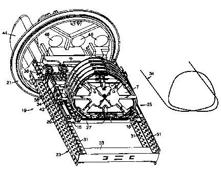
Figure 3 shows an optical fibre organizer 19 which has been assembled and
attached to a base 21 of a cable closure. The organizer 19 comprises a support
frame
23 and a storage module 25 attached to the support frame. The storage module
25
comprises a support plate 27 (of similar, but slightly different, design to
the support
plate shown in Figure 1) supporting a plurality of hinged optical fibre
storage trays 7.
Each support plate 27 includes attachment devices 29 which are interlocked (by
a
snap-fit) with the support frame 23. The support frame 23 comprises two pairs
of
spaced-apart elongate parts 31 which are interconnected by an elongate cross-
member
33. Each elongate part 31 is anchored to the base 21 of the closure.
The routing of the uncut optical fibre(s) of a single circuit or a single
cable
element, on the organizer, is shown schematically by means of a thick black
line 34.
The path of the optical fibre(s) 34 is also illustrated schematically adjacent
to the
organizer. (The path will be described with reference to a single fibre, for
clarity).
The fibre extends from the region of the organizer which is adjacent to the
base 21 of
the closure through open-sided guides 36, 38 and 42, and through the open-
sided
routing channel 15 on the support plate 27. The fibre then extends into an
open-sided
guide groove 5 (see figures 1 and 2) in the support plate, and towards the
opposite
edge of the support plate. The fibre then extends into a storage tray 7 which
is
associated with that particular guide groove 5, it is looped one or more times
in the
tray (depending upon the length of fibre to be stored), and then extends out
of the tray
and back into the guide groove 5. The fibre extends along the guide groove 5
once
more, and then extends out of the opposite end of the guide groove to that
through
which it entered. The fibre then extends along a routing channel 15 situated
beyond
this opposite edge of the guide groove back towards the base region of the
cable
closure.
I II ~ ~
CA 02271881 1999-05-11
WO 98/21955 PCT/US97/21357
An optical fibre cable (not shown) carrying the uncut optical fibres which are
stored on the organizer in single circuits, or single elements (as the case
may be) enters
the cable closure through an oval port 44 in the base of the closure. In
particular, a
loop of the cable is fed through this port, and the optical fibres are exposed
and
organised as desired in the closure. Normally, some of the optical fibres will
be cut
and spliced to optical fibres from other cables which extend into the closure
through
cable ports 46. The splices and associated fibre lengths are also stored on
respective
storage trays 7, in single circuits, or single cable elements (as the case may
be). The
organizer, and cable closure, will therefore normally store both uncut (and
therefore
unspliced) and cut (and spliced) fibres, in single circuits or single cable
elements.
-